1
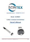
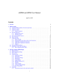
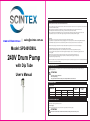
A. SAFETY
All safety instructions must be observed and followed before use.
1. There are high speed rotating components. Failure to follow the safety instructions may lead to serious injury. All safety instructions must
be observed and followed strictly.
2. Before installing and starting the barrel pump the use should have suitable qualifications and is be familiar with this manual.
3. The installation and maintenance must be according to current machinery and electrical standards.
4. The spare parts life time will be limited by wear and corrosion. The failure is affected by operating environment. The user has the
responsibility to operate in accordance with regulations. Regular maintenance should be performed regularly.
www.scintex.com.au |
[email protected]
When Using
1. Wear protective clothing, goggles in accordance with safe practice and materials handling.
2. It is prohibited to use plastic or aluminum alloy pump piping and non-explosion proof motors when transferring flammable liquids.
3. For flammable liquids, the earth wire must be installed along with an electrostatic protection device and conductive hose.
4. Make sure the pump pipe is inserted into the liquid completely before using. Make sure all connections are liquid tight.
Model: SP240VD90L
240V Drum Pump
with Dip Tube
5. Suitable flexible pipe must be used when transferring high temperature liquids.
6. Ensure the pumped liquids temperature, viscosity and density do not exceed the stated upper limits for this pump.
7. Use a suction filter in the pump tube when transfering liquids with impurity or solids. To avoid the blocking, please check and
clean regularly.
8. Make sure the pump is under supervision before powering on. Never leave the pump unattended when in use.
9. Do not touch the tube bottom after switching on the pump. The impeller spins at high speed and may lead to
equipment damage and personal injury.
Make sure the pump tube is operating in the vertical position. Never upend or lay flat after using. Pay attention to residual liquids which may
lead to injury or cause environmental damage.
B. MACHINE DESCRIPTION
MOTOR: AC series motor with overheating protection components, Quick coupling adapter, Automatic positioning coupling and
Adjustable speed switch.
User’s Manual
ATTENTION!
• Never leave the pump unattended.
•Neverrunthepumpdry.
• The pump should not be immersed deeper into the liquid than the outlet connection.
C. TECHNICAL DATA
C1. Electrical Data
PUMP MODEL
ELECTRICAL POWER
Current
Voltage(V)
Power (W)
Load Speed
(RMP)
Rated Speed
(RMP)
AC
230
450
3000~11000
20000
SP240VD90L
D. OPERATING CONDITIONS
D1. Environmental Conditions
Electro-Motor operating environment: -25~40˚C
D2. Power Supply
Make sure that the supply voltage corresponds to the voltage indicated on the rating plate.
ATTENTION!
Power from lines with values outside the indicated limits can damage the electrical components.
1 of 4
J. PROBLEMS AND SOLUTIONS
E. MOVING AND TRANSPORT
Ensure the pump and pump tube are packaged properly for transport.
PROBLEM
No flow rate or small flow rate
F. INSTALLATION
Safety Check
Make sure that the supply voltage corresponds to the voltage indicated on the rating plate.
7.1 Motor Installation
1. Pump tube check: Make sure every joint has a good seal.
2. Motor Check: Make sure the power cable c and switch are in good condition.
Do not put hands near the motor output shaft.
3. Put the motor coupling is directed at the pump tube. Make sure the pump tube head is inserted into the motor head completely.
4. The motor and pump tube position can be adjusted by 360°. Put the pump tube adjusted to the suitable position and lock the nut to
finish the installation. It is recommended that the pump discharges away from the motor power cable.
7.2 Start
Make sure all the joints are sealed. The tube outlet must be fixed well to avoid pressure leaking.
F7. Electrical Connections
•Terminalstripboxconsists
- ON/OFF switch;
of:
- Speed regulating knob switch
- Speed regulating circuit board
• 5M Power cable
AC
Vibration and noise
Pump tube leakage
Switch
POSSIBLE CAUSE
CORRECTIVE ACTION
Loss of power source
Check power supply
Motor failure,
Motor Check
Outlet closed or blocked
Open the outlet valve and check
Suction lift too great
Short the transportation distance and height
Liquid viscosity too high
Check the type with supplier
Liquids draining out
Stop the pump
Blocked inlet
Clean the inlet
Liquids draining out
Stop the pump
Motor overload
Check the liquids viscosity and pump lift
Sliding bearing damage
Change the sliding bearing and seal ring
Coupling wear
Change the coupling
Seal ring wear
Change the seal ring
Circuit failure
Check the circuit
Overuse of the motor, overheating
Restart the motor after cooling down
protection, electric brush damage
Change the electric brush
K: DIAGRAM & PARTS LIST
Speed
regulating
circuit
board
M
ATTENTION!
IT IS THE INSTALLER’S RESPONSIBILITY TO PERFORM THE ELECTRICAL CONNECTIONS WITH RESPECT TO SAFETY
REGULATIONS.
G. DAILY USE
No.
Qty.
No.
Qty.
No.
Description
1
Tapping screw
3
9
Lining
1
17
Motor
1
2
Speed control knob
1
10
Speed control circuit board
1
18
Cable
1
3
Switch block
1
11
Motor shell
1
19
Coupler
1
4
Countersunk head tapping screws2
12
Tapping screw
3
20
Bottom cover
1
5
Head cover
1
13
The handle cover
1
21
Flat gasket
3
6
Tapping screw
2
14
Binding post
1
22
Spring washer
3
7
Rotary knob connector
1
15
Wire pressing piece
1
23
Bolt
3
8
Toggle switch
1
16
Cable shield
1
24
Tapping screw
8
Description
Description
Continuous running may cause motor overheating, the overheating protection system will cut the power automatically. The
motor can be restarted again after cooling down by pressing the on/off button.
ATTENTION!
Thesuggesteddutycycleis2hours.Donotexceedonehourwhentheenvironmenttemperatureismorethan30˚C
Please change the electric brush every 250-300hours
H. NOISE LEVEL
Under normal working conditions the noise emission from all models does not exceed the valve of 80 db at a distance of 1 meter from
the electric pump.
I. DISPOSING OF CONTAMINATED MATERIALS
In the event of maintenance or demolition of the machine, do not disperse contaminated parts into the environment.
Refer to local regulations for their proper disposal.
2 of 4
3 of 4
Qty.
1
2
3
6
4
5
7
8
9
10
12
11
13
14
1
15
17
16
18
19
20
21
23
24
4 of 4
22