1
GPS2CAD
User's Manual
© AMC Inc. 2004
© AMC Inc 2004
Table of Contents
Welcome
What's New
Video Help
Quick Start
3
3
4
4
The IMPORTANT Stuff
Purchasing
6
6
Purchase On Line
Upgrading
6
6
Quick Look
7
Tour
Features
7
8
Preferences
9
Grids and Units
GPS Units
ACAD Settings
Misc
9
11
12
12
the MAIN PROGRAM
13
Splash Screen
Open/Save Projects
Connecting to GPS
Downloading Points and Routes
Grid Columns
Sorting Points
Main Window Controls
Direction Distance Grid
Round-off
13
14
14
16
18
20
21
22
23
Working with AutoCAD
24
Sending Points TO AutoCAD
Getting Points from AutoCAD
24
25
Points and Routes
25
Editing Points and Routes
Selecting and Unselecting Points
Adding / Deleting Points and Routes
Moving Points in the grid
25
26
26
27
Maps
28
Sample Maps
Map Window Controls
Viewing Selected Points
Using the Preview Map
Viewing the Map Window without points
Deleting Points and Routes
Zoom To Point
Add Points
Moving around on a map
28
31
32
33
34
35
36
37
38
p1
© AMC Inc 2004
Deleting points on Map
About Map Scale/Zoom
About using the maps in AutoCAD
38
39
40
Real Time Capture
40
Capturing Points
To Access
40
42
Printing
43
Printing
Print Preview
Print Setup
43
44
45
Importing and Exporting data
46
Introduction
Importing Points FROM AutoCAD
Importing from Garmin's MapSource
Importing from Magellan's MapSend
Importing from Other
Get Points tab
Type of Points tab
Datum Selection tab
Zone Selection tab
Column Assignments tab
Grid Selection tab
Select Points tab
Verify and Import tab
Exporting Points
Select File
Select Points
Select Columns
DXF Info
Export
46
47
49
52
55
55
56
58
58
59
63
65
66
67
67
69
70
71
72
Knowledgebase and FAQ's
73
Knowledgebase and FAQ's
73
The FUN Stuff
73
FUN Activites
73
The OTHER Stuff
74
GPS2CAD Supported Projections
Other Resources
74
75
p2
© AMC Inc 2004
Welcome
GPS2CAD is a powerful program that allows you to connect to a portable GPS device, download
the waypoints, routes, and trackpoints, and do some amazing things with them:
Convert them to the datum of your choice and plot them in AutoCAD
Automatically view them on Aerial Photos, Topo maps, or Tiger maps (census maps) all
retrieved from TerraServer-USA, one of the largest repositories of public domain
mapping on the net
Export them to a variety of formats for use in other programs
Edit the points
Upload them back to your GPS unit.
-o-
What's New
Product revisions - you can view the latest revisions to GPS2CAD on the website: click
here
Help Document Revisions: the following is a list of the changes to this help document
p3
© AMC Inc 2004
1-28-2005
Updated Help files to match Version 3.5.
Includes major sections on:
Information on the new website
GPS2CAD.com
Information on new Video Help Files
Importing points from AutoCAD
Importing points from Garmin's MapSource
Importing points from Magellan's MapSend
Importing points from Other sources
Exporting points to several formats
Saving/Opening Project Files
6-24-04
Added:
Magellan Support
3D plotting for points and blocks
Options to regen and zoom extents in
ACAD during real time capture
Button to Sort Points in grids
Fixed:
Altitude wasn't being recovered during
some point downloads
Oversize pictures in help file
All three direction-distance grids now work
together
Fixed error that occurred when clicking the
cancel button during a .dxf import/export
fixed a program crash when exporting dxf
files to a drawing that was open in ACAD
3-25-04
Added What's new section
Added FAQ about plot preview click here
-o-
Video Help
In order to make GPS2CAD even easier to use, a library of "Video Help Files" is maintained on
the website GPS2CAD.com. Click Here to view them. This is an on-going project, so if you don't
see what you need check back at a later time.
-o-
Quick Start
The following steps will get you going simply and easily:
Start GPS2CAD Ver. 3.5
From the File Drop down menu select Preferences
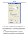
In the Preferences Window
Select the “GPS Setup” tab
p4
© AMC Inc 2004
Make the following selections:
o The com port your GPS is connected to.
o The make of the GPS unit
o GPS model type. The Garmin model types are distinguished by the number of
symbols they maintain internally, either 16 symbols for early models, or greater than
16 symbols
NOTE:
Magellan units must be set to a baud rate of 4800, and the NMEA string = V2.1 GSA. To do
this, use the menu button on the GPS unit to set these values: press Menu\Setup\Baud
Rate\4800 Baud and Menu\Setup\NMEA\V 2.1 GSA
Select the "ACAD Settings tab and choose:
The Layer and Scale for plotting Blocks in AutoCAD
The Layer and Color for plotting lines and points in AutoCAD
Select the “Grid and Units” tab
Select the desired output datum. To start, we recommend American
Projections/UTM_NAD_27. This is the default setting for translating from WGS 84 datum
From the Units drop down box select US_Foot (best used for everything except the unique
American datums
Leave the other settings at their default values
Click “Save and Close” button
In the Main Window
From the Main Form, click “Connect GPS”
Wait for the green light to appear indicating "Connection OK"
Click “Get Waypoints”
The points are loaded………
Viewing Maps
Left click in the point grid and drag to highlight the points you want to view or plot
To view the points on a TerraServer-USA map, click “View Points” for an Aerial, or select the
down arrow and then the map type you want.
Plotting in AutoCAD
Start AutoCAD, begin a drawing, and then minimize the session of AutoCAD
Return to GPS2CAD.
Select the points to plot in the Waypoint Grid
Click the “Plot Lines” button to plot the points as lines
You will receive a “Plot Complete” message
Return to AutoCAD to view the points
That’s all there is to the Quick Start!
-op5
© AMC Inc 2004
The IMPORTANT Stuff
Purchasing
Purchase On Line
How To Purchase GPS2CAD
Purchasing GPS2CAD is quick and easy:
On the File drop down menu, select "Purchase". This will take you to our credit card
processing site known as "ShareIT"
Select the license model you want. Four are available:
Single license - entitles you to one copy of the program
Combo license - entitles you to three copies of the program, one office, one laptop, one home
Site license - entitles you to use the program on all the computers at one site. This means a
single street address. If a company that buys it has branch offices in several locations, a site
license permits you to use the program at one site.
World license - entitles you to use the program at all the branch offices of a single company.
This does not include affiliate companies, or companies owned by one which purchases the
program. It's one company - i.e. "XYZ Corporation", world wide.
Follow the online instructions for purchasing. Note that there are also provisions for ordering
by fax or purchase order.
Once the funds clear, you will be mailed a user name and release code. KEEP THESE IN A
SAFE PLACE! YOU WILL NEED THEM FOR ANY RE-INSTALLATION. KEEP THEM IN A
COMPUTER FILE BECAUSE THE RELEASE CODE IS VERY LENGTHY, AND BEST ENTERED BY
"CUT AND PASTE"
Once the release code has been accepted by GPS2CAD, re-start the program. The 5-point
restriction is removed, and the main window header no longer reads "Demo Version..."
-o-
Upgrading
When upgrading to the latest version of GPS2CAD, you may need to do an uninstall of the old
p6
© AMC Inc 2004
version and a new install of the latest version. The program uses Install Shield and is a
straight-forward process.
When upgrading from a 3.1.xx version to 3.5.xx version, a new license key is required. This is a
no-cost upgrade, and the keys are available from the publisher for paid owners. See the website
www.gps2cad.com for contact information.
When upgrading within the 3.5 series, the same license key should continue to work as it did
before (you kept it, right?).
The first thing you should do upon beginning the new version is to go into the setup and verify
your preference settings; you may have to re-apply the correct settings.
As always with a computer, BACK UP YOUR HARD DRIVE before installing new software,
including GPS2CAD!
-o-
Quick Look
Tour
Main
features:
Works with most Garmin and Magellan GPS receivers
Imports waypoints, routes, and tracks
Works with AutoCAD versions 14.01, 2000,2002,2004, 2005
Plots the points on public domain Aerial Photos, Topo Maps, and Tiger Maps
Works in English and Metric units, including the U.S. foot (slightly different than
“International” foot)
Exports and imports Waypoints, routes, and track points to/from
o .dxf files for use in other CAD programs, including AutoCAD Lt.
o Access 2000 .mdb
o Text files – comma, tab, or space delimited
o Garmin MapSource
o Magellan MapSend
Built in Help files (you’re reading them!) that are web-based so you always have a
current version
Video Help Files
Performs “Real Time” capture of points, with output to the main grid, AutoCAD, or an
Access Database.
Supported by a dedicated website at www.gps2cad.com
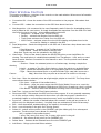
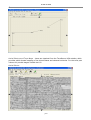
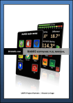
There are two main components:
The main screen, where the points are stored and edited:
p7
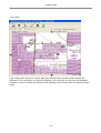
© AMC Inc 2004
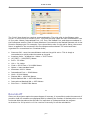
The Mapping windows, where your choice of Aerial, Topo, or Tiger maps are displayed:
-o-
Features
AutoCAD Features
Can select to plot points (AutoCAD Nodes), lines (AutoCAD Light weight polylines), or
blocks
3D plotting of points and blocks into AutoCAD
Allows the manipulation/relocation of points within AutoCAD and then the reload of the
points back to GPS2CAD, and back to the GPS unit.
Real time capture and plotting of points! Yes, you can drive around the city with your
GPS and laptop operating, and watch the lines appear tracing your route
Mapping Features
Plots the points on public domain maps from TerraServer-USA, a joint venture between
the U.S. Geological Survey department and Microsoft
o Aerial photos at 4 resolutions
o Tiger maps (census maps)
o Topographic maps at various resolutions
Scroll to new locations on the maps, or define the location to view by latitude/longitude
Plots a preview map showing points, lines, and labels
p8
© AMC Inc 2004
Allows the placement of new points on a photo/topo map, and then sending that point
back to the main grid for AutoCAD plotting or upload to GPS
Allows saving the map/point image to a file
Provides a convenient internet link to buy the map you are viewing
Allows addition/deletion of points to the map and the main grid
Preferences
Select an output from 46 different artesian grid systems covering most of the world,
including United States, Britain, Europe, Australia, and New Zealand
o UTM
o NAD 27
o NAD 83
o State Plane Coordinate systems
User selectable round off of numeric data (full numeric data is preserved for calculations)
Provides short help notes about the datums
Selection of plotting layer and color for AutoCAD
Import/Export Features
Exports .dxf,
Imports/Exports text files (comma, tab, or space delimited)
Imports/Exports Microsoft Access 2000 database
Printing Features
Prints copies of waypoints, routes, and trackpoints
Print Preview function
Other features
Web based purchase, with almost immediate access to the release code
-o-
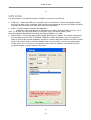
Preferences
Grids and Units
The native format for points in the GPS receiver is WGS 84, a Latitude/Longitude format. Since
this is not compatible with X,Y,Z of CAD programs, they are converted to one of many Cartesian
(X,Y,Z) formats available around the world. In the "Grids and Units" tab of Preferences you
specify the Output Datum and Units for the converted points.
There are several Units available to choose from:
INT_FOOT - an International Foot, which is defined as 0.3048 Meters
US_FOOT - used primarily with American projections, especially the State Plane Coordinate
System. The US_FOOT is defined as 0.304800609601 Meters or (1200/3937 ) x Meters
METERS - The native format of the GPS. It is also the standard measurement for UTM grids
IRISH_FOOT - used with surveys in Ireland. Defined as .3048007491 Meters
It's IMPORTANT to understand that these four UNITS are used to convert the GRID
COORDINATES shown when the program receives the points from the GPS unit. The numbers
affected by these units are those in the "As CAD Points" column of the grid.
There is another Units drop-down box shown with the "Direction Distance" grid of the main
program window. These units affect only the measurements in the Direction Distance grid. More
p9
© AMC Inc 2004
on this can be found here.
The output grid should be selected by clicking on the desired "node". When available, comments
regarding each datum appear in the "Comments" box. The Datums have been organized into
"American Projections", "European Projections", "Pacific Projections", and "Universal
Projections". These are our designations for simplicity, and carry no other special significance. A
complete list of the supported datums is listed here. However here are some simple guidelines:
UTM_NAD_27, UTM_NAD_83 - these are Universal Transverse Mercator projections based on
either the North American Datum 27 or 83. Use these when you know you're trying to match
up a specific projection.
SPCS_27, SPCS_83 - These are the U.S. State Plane Coordinate System, based on either
NAD 27 or NAD 83 datums. Note that you must know which State Zone the points on the
GPS are in, and select that zone (since the state zones are so irregular, it is virtually
impossible to derive them from the Point's Lat/Long). If you don't know the zone, find out
before using the program. Note that ALL THE POINTS MUST BE WITHIN THE SAME ZONE!
because the coordinate system of each zone is repeated.
Universal Projection\UTM_NORTH - this is a simple WGS 84 datum for use in the Northern
Hemisphere. If you don't have any other special requirements, and the points are in the
Northern Hemisphere, try using this. If you're in the Southern hemisphere, choose
UTM_SOUTH.
p10
© AMC Inc 2004
-o-
GPS Units
Use this section to provide information needed to connect your GPS unit.
COM port - select the COM port your GPS unit is connected to. These are typically a Serial
port on the back of the computer. USB ports are not supported, but you can obtain 3rd party
software that will make your USB port look like a Serial port.
Make - Choose between Garmin and Magellan.
Magellan units must be set to a baud rate of 4800, and the NMEA string = V2.1
GSA. To do this, use the menu button on the GPS unit to set these values: press
Menu\Setup\Baud Rate\4800 Baud and Menu\Setup\NMEA\V 2.1 GSA
Select Model - Choose the appropriate model. Note that for Garmin, the models themselves
are not listed, but the TYPE of SYMBOL LIBRARY is listed. We feel it's just not practical to
keep up with all the models available, therefore we have used this method: the older models
have a 16 symbol library, the later models have more (it varies). Choose the appropriate
model, and if you're not sure, try the Other. Note that this selection only affects how the
program assigns a symbol name to the point.
-op11
© AMC Inc 2004
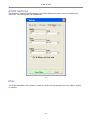
ACAD Settings
This section is used to specify settings used when placing the points, lines, and blocks into
AutoCAD. The settings are self explanatory.
-o-
Misc
The Preferences/Misc. tab contains a check box that controls whether the Intro Video is shown
on startup.
p12
© AMC Inc 2004
-o-
the MAIN PROGRAM
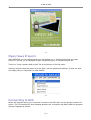
Splash Screen
The splash screen appears on Startup. It contains a link to the Video Help page of the website
www.gps2cad.com. We recommend that you take a look through the available help videos on
the website. It is an on-going project, so be sure to check back often.
p13
© AMC Inc 2004
-o-
Open/Save Projects
With GPS2CAD you can save projects you are working on, or open a project that you have
saved. To do this, go to File/Open Project; File/Save Project, or File/Save Project As.
There is a "most recently used project" list at the bottom of the file menu.
Saving a project saves the points in all the grids, and the preference settings. It does not save
the maps that you may have in a map window.
-o-
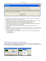
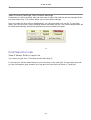
Connecting to GPS
When the program starts, you must first connect to the GPS unit if you are going to retrieve it's
points. The "Connection OK" box indicates whether the connection has been made. On program
startup it appears as shown:
p14
© AMC Inc 2004
Note that many portions of GPS2CAD are still usable without a GPS connection. This includes
adding and viewing your own points, importing and exporting points, connecting to AutoCAD,
just about any function that does not require a GPS data or function.
When a connection to the GPS unit has been established, you will see "Connection OK":
If the connection fails, you will see "No Connection:
Should this occur, you should click the "Connect GPS" button to establish or re-establish
connection to the GPS.
Troubleshooting your GPS connection
Few things can go wrong when connecting to the GPS unit, but on occasion it can become a
problem. Here are some guidelines for resolving the connection:
If you encounter an error while trying to connect, you may receive this error message:
p15
© AMC Inc 2004
Magellan units sometimes require a second click shortly after the first to establish a
connection (don't ask why...we're working on it!)
Magellan units must be set to a baud rate of 4800, and the NMEA string = V2.1 GSA.
To do this, use the menu button on the GPS unit to set these values: press
Menu\Setup\Baud Rate\4800 Baud and Menu\Setup\NMEA\V 2.1 GSA
Double check the COM port that you have selected in the GPS2CAD Setup window. Make
sure it is active and connected to your GPS unit
Make sure the GPS is turned on. Oddly enough, this is frequently the cause of "No
Connection"
Check that your GPS unit has fresh batteries. Generally, low battery power will cause the
GPS to turn itself off; so even thought you "know you turned it on..." it may have turned
itself off because of low batteries.
Check the output Interface settings of the GPS units. For Garmin, the settings should be:
Format: Garmin
Transfer Mode: Host
-o-
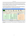
Downloading Points and Routes
Once the connection is established, downloading points and routes can be done by simply
clicking a button. To download the points, you may click on the Toolbar "Get Waypoints" button,
or the down arrow that reveal additional choices:
p16
© AMC Inc 2004
Routes can be downloaded by clicking the Routes on the toolbar or Get Routes from the Drop
Down menu. Clicking on "Track Points" or "Get Track Points" similarly will download the Track
Points from the GPS Unit. The Track points are those that are automatically recorded by the GPS
unit and provide the "bread crumb" track of your location.
Note that there are three grids: one for Waypoints, one for Routes, and one for Track Points.
The points are automatically loaded into the proper grid, and you may switch between them by
clicking on the Waypoints, Routes, or Track Points button above the grid.
Routes appear in the main Route grid and the Route Direction Distance grid with a "Header" row
that contains the route name and a "+" button that allows you to expand/collapse the points in
the route:
p17
© AMC Inc 2004
-o-
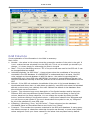
Grid Columns
Some explanation of the information in the Grids is necessary:
Main Grids
Number - the values in this column show the consecutive number of the point in the grid. It
is not a value that was extracted from the GPS unit. This is not a number you should try to
change - it is there simply for referencing the Point in the grid
Ident - This is the Identifying name or "ID" of the point that was used in the GPS unit. It can
be changed/edited as needed.
Latitude/Longitude, "as GPS Points" - these columns show the coordinates of the point as
contained in the GPS database. It is IMPORTANT to understand that in all cases, the GPS
units maintain an internal database in WGS 84 datum - the native format designed for
satellite/GPS work. Most GPS units will DISPLAY the points in several different datums, but
they are maintained internally in WGS 84, and this is the format that is downloaded from the
GPS.
Altitude - if the GPS unit maintains the altitude of the point in it's internal database, it is
downloaded and shown here. As with datum projections, most GPS units show the calculated
altitude on the screen, but relatively few units maintain the altitude in the database. More
about Altitude can be found here
Symbol - This columns shows a text description of the Symbol number used by that point.
Different GPS units have different Symbol libraries, and the correct library is used in this
column, based on the Setup selections. You can change the symbol by clicking the Edit
button, and then clicking in the Symbol column - a drop-down selection box will appear and
you can choose a new symbol. If you are in doubt about the symbol to use, try "Waypoint"
as this is like a default for most GPS units.
X(Easting), Y(Northing), Zone, "as CAD Points" - These columns show the calculated
coordinates based on the selected Datum and Units from "Setup".
Comment - This contains the comment contained in the GPS point database. In many cases,
the default comment is a date/time value that the point was entered, or some other default
values assigned. Check your users manual for the values that are placed here by default.
p18
© AMC Inc 2004
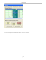
Direction Distance Grids
The Direction Distance grids show the information from point to point of those shown in the
main grid to it's left.
Number, Ident - these columns are extracted from the grid to the left, showing the
consecutive number of the point and it's given identification
Direction - the direction is calculated as an azimuth (0 to 360) in Degrees, based on a
simple geometric calculation of the Grid coordinates (as CAD Points) of each point. No
attempt at showing differences between True North and Magnetic North is made. Note the
Units drop down box above the grid. This can vary the Distance value shown in the grid,
based on the selected units. More about this is found here.
p19
© AMC Inc 2004
-o-
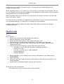
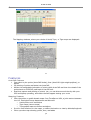
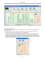
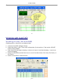
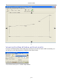
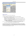
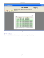
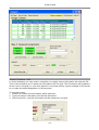
Sorting Points
The Sort button on the main toolbar will sort the points in the Waypoint grid in several ways.
The default sort is Numeric by point number. The other options are shown on the button's drop
down menu:
Sort by Ident (Alpha) and sort by Ident (Numeric) is provided to overcome the problem of
sorting an alpha string as a numeric string. The following illustrates the difference in the sort:
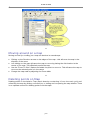
Sort Ident (Alpha) - notice that the points are
sorted by the ident column, reading the numbers
as alpha characters.
-o-
p20
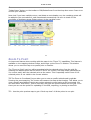
Sort Ident (Numeric) - notice that the points are
sorted by the ident column, reading the numbers
as numeric values.
© AMC Inc 2004
Main Window Controls
This section provides an overview of the controls on the main window. Where more information
is available, it is shown by link.
Connection OK - shows the status of the GPS connection to the program. More about that
here.
Connect GPS - makes the connection to the GPS. More about that here
Get Waypoints - this command is the most frequently used of those for downloading points,
and is placed as it's own button. It simply downloads the waypoints from the GPS unit. Note
the Down Arrow to the right - this provides additional choices:
* Waypoints - a repeat of the Tool bar button
* Routes - retrieves the Routes from the GPS unit
* Track Points retrieves the Tracks from the GPS unit
* ACAD Points - retrieves points from the ACAD drawing and places them in the
grid, to
be used for viewing or upload to the GPS
Send Waypoints - Sends the Waypoints to the GPS unit. It also has a drop down menu that
includes:
* Send Waypoints - a repeat of the Tool Bar button
* Send Routes - sends the routes to the GPS unit
Note that Tracks may not be uploaded to the GPS unit
View Points - This tool bar button places the SELECTED points on an Aerial Photo for
viewing. The aerial photo is obtained automatically from TerraServer - USA, and you must
have an active Internet Connection for this feature to work. The Drop down menu allows
these choices:
* Preview - Places the selected points on a Preview map, showing a simple line
drawing
* Aerial - a repeat of the View Points button, shows the points on an Aerial Photo
* Topo - Places the selected points on a Topographic map from TerraServer-USA
*Tiger - Places the selected point on a public domain Tiger map (also known as a
Census
Map). Note that only one point at a time can be shown on this map.
Plot Lines - Plots the selected points as a light weight polyline in AutoCAD. The Drop down
menu allows these choices:
* Plot Lines - a repeat of the toolbar button
* Plot Points - plots the points as an AutoCAD Point (Node). Be sure to reset the
AutoCAD variables PDMode and PDSize to something that is visible!
* Plot Blocks - inserts a block with attributes showing most of the data in the grid.
Real Time - brings up the Real Time Capture window
Disconnect GPS - Disconnects the GPS unit from the program. It is not generally necessary
to do this, and an orderly disconnect is done when you end the program. However it is
sometimes helpful to connect/disconnect/reconnect, and it is provided for this reason.
Round off - selects the number of decimal places the numbers in the grid are shown to. It
affects only the displayed numbers - internally they are maintained to their full accuracy.
Edit - when depressed, enables editing of the values in the main grids
Sort - sorts the points in the grid. See "Sorting Points"
Select All - selects all the points in the CURRENT grid (the visible grid) for a subsequent
operation. The drop down menu allows for selecting
*All ( a repeat of the toolbar button)
* every 2nd, every 3rd, every 5th, or every 10th point in the grid
Unselect All - de-selects all the points in the CURRENT grid
Delete Items - Deletes all the Selected items from the CURRENT grid
Add Points - Brings up the Add Points window
p21
© AMC Inc 2004
Find Points - Brings up the Find Points window
Waypoints/Routes/TrackPoints tabs - displays the respective grid. Note that all of these can
be populated at one time, and you can click between them for viewing
Current Position Label - shows the current position being read from the GPS unit screen/real
time information ( not the database)
Total Waypoints - shows the total waypoints in the Current Grid
Datum - Shows the current Datum and Zone (if applicable) that has been selected in Setup
Grid Units - Shows the current Grid Units that were selected in Setup
-o-
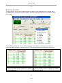
Direction Distance Grid
The Direction - Distance grid shows the Azimuth in Degrees and distance of each leg,
referencing the point grid to it's left. The Number and Ident columns provide the consecutive
point number and the identifying name, while the Direction and distance between that point and
the next is shown in the next two columns.
p22
© AMC Inc 2004
The "Units" drop down box requires some explanation. The units refer to the Distance units
shown in the Direction Distance Grid. The Point grid may reflect the CAD coordinates in one
of four units: Meters, International Foot, U.S. Foot, and Ireland Foot, and these are selected in
the Preferences section. Each of these selections is converted to the desired Distance unit in the
Direction Distance grid. For example, if you chose Metric units for the grid in Setup, the correct
factor is applied for the conversion into the distance units selected. The units have been
organized for convenience into "American Units",
Same as Grid - uses the same distance units as the grid is set to. This is simply a
convenience to quickly select the same as the grid
American Units - all based on 1 Meter = 39.37 inches
US_FOOT = (1200/3937) Meters
Rod = .25 chains
Link = .01 chains
Chain = 66 US Feet = 20.11684 Meters
Meters = base standard used
Kilometers 1000 X Meters
International Foot = .3048 Meters
Yard = 0.9144 Meters
Statute Mile = 1609.344 Meters
British Nautical Mile = 1853.184 Meters
International Nautical Mile = 1852 Meters
Irish Foot = .3048007491 Meters
-o-
Round-off
Since not all projects require the same degree of accuracy, it is possible to select the amount of
precision that the numbers are displayed with by selecting the number of decimal points on the
horizontal slider bar above the Grid tab. It's important to understand that the program
maintains the full precision of the number internally for all the calculations.
p23
© AMC Inc 2004
-o-
Working with AutoCAD
Sending Points TO AutoCAD
Sending points to AutoCAD is a simple process:
Verify the AutoCAD settings in Setup
Select the points to plot. These may be Waypoints, Route points or Track points. DO NOT
select a Route Header.
Start AutoCAD and begin a drawing. (it does not have to be a blank drawing - it can be an
existing drawing).
Return to GPS2CAD and click Plot Lines or one of the Menu items: Plot Lines, Plot Points, or
Plot Blocks
Return to AutoCAD to view the items
p24
© AMC Inc 2004
A few notes about the items plotted:
Lines are not plotted in 3D. Points and blocks may be plotted in 3D depending on the setting
in preferences. Default is 3D
Plot Lines - This plots an AutoCAD Lightweight Polyline. Note that this is different than the
"Real Time" plotting, which uses regular lines. Lightweight polylines do not have an
elevation attribute for each vertex - that's why they're "Lightweight", and also why they are
not inserted in "3D".
Plot Points - plots an AutoCAD Point (also known as nodes). MAKE SURE you have your
AutoCAD settings so the points are visible. If you're not sure, set PDMode = 32 to display
points as a Circle, and set the PDSIZE = something greater than zero. These can be set from
the ACAD command line by typing PDMODE, enter or PDSIZE, enter
Plot Blocks - this uses a block with Attributes to display the point information shown in the
Grid. Blocks take a long time to plot, and add a lot of clutter to the drawing, so use them
sparingly
-o-
Getting Points from AutoCAD
See the section Uploading Points FROM AutoCAD
-o-
Points and Routes
Editing Points and Routes
The Point information in the main grids can be edited. However during normal use, they are
locked to prevent accidental changes. In order to Edit the points, you must click the "Edit"
button. This will enable the main grids to be edited, and it will remain this way until the button
is clicked again.
When editing, most of the information can be changed. If the coordinates are changed, the
corresponding coordinate calculations are made and shown (as GPS Points/as CAD Points). If
you upload to the GPS, the changed points will be used. However it depends on the GPS unit as
to how it will handle points that it thinks are duplicates - some will overwrite, some will add as
new. Be careful when uploading possibly duplicate points!
p25
© AMC Inc 2004
-o-
Selecting and Unselecting Points
Selecting points for Editing can be done in several ways:
Click and drag to highlight the points
Press the Select All button (or drop down menu item Edit...) to highlight all the points
Press "Every nth" to select every 2nd/3rd/5th/10th row in the active grid. This is especially
useful if the points are close together (such as a track log) and you don't need all of them.
Once selected, you may delete them to reduce the total points, or view them to get a clearer
picture.
-o-
Adding / Deleting Points and Routes
Adding Points and Routes:
Points and Routes can be added to the Waypoint, Route, and Track point grids. In order to add
points, click the Add Point button on the toolbar. The Add Point window will appear and you can
fill in the desired information. Press OK to insert the point. The point will be inserted at the end
of the grid. If you then want to move it to another row, you can Edit - right click - and drag to
the new location (see Moving Points)
p26
© AMC Inc 2004
Deleting Points and Routes:
To delete an item, first select (see Selecting...) then press the Delete Items button
-o-
Moving Points in the grid
Points may be moved to a new location in the grid by following this procedure:
Click the Edit button and make sure it is depressed
Highlight the point to move by clicking it's row\
p27
© AMC Inc 2004
Right - click the highlighted row, and while holding down the right-click, drag the point to a
new location. A thick indicator bar will show the new location
Release the right-click at the desired location
Click the Edit button to prevent editing
Note that the points will be renumbered consecutively
-o-
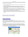
Maps
Sample Maps
Four types of maps are available in GPS2CAD:
Preview
The preview map is provide for the convenience of seeing the selected points as a simple
line-plot with labels. It is generated within GPS2CAD and does not rely on AutoCAD. More on
using the Preview map can be found here.
The following is a sample of a Preview Map:
p28
© AMC Inc 2004
Aerial Photos and Topo Maps - these are obtained from the TerraServer-USA website, which
provides public domain mapping of the United States and selected territories. For the most part
it does not provide images outside the U.S.
Aerial Photo:
p29
© AMC Inc 2004
Topo Maps:
Tiger Maps (also known as Census Maps) are obtained from another public domain site.
Because of the restrictions of this kind of display, only one point at a time can be displayed.
However it is more flexible with display Scale, allowing more choices than the aerial and topo
maps.
p30
© AMC Inc 2004
-o-
Map Window Controls
The map windows have their own toolbars and controls:
Save Map - brings up a dialog box that saves the current map as a bitmap file. In case
you're wondering about sending the map into AutoCAD, click here
Close - closes the window
Add Points - brings up the Add Points dialog window
Zoom To - brings up the Zoom to Point dialog window
Plot Color - brings up a color dialog box that lets you select the color to plot the point
symbol in
Marker Shape - selects the marker shape to use when plotting the points on the map
"Zoom" slider bar - adjusts the map scale that is retrieved from the TerraServer - USA site
that supplies the map. For more information on how this works, click here
Show Point Names - Sometimes the names of the points can become cluttered. This check
box turns off the names and leaves the marker. To reduce the clutter even more, choose a
dot as a marker
Scroll Arrows - let you scroll the map to a new location.
Buy this Map - takes you to our website so you can purchase the map shown in one of many
different formats (paper, digital, DEM, etc.)
GPS2CAD What's New - takes you to our web page that keeps you posted on new features
and revisions to the program
p31
© AMC Inc 2004
-o-
Viewing Selected Points
In order to view the points on an Aerial Photo or Topo map, follow this procedure:
Select the points to view in any one of the main Grids (Waypoints, Routes, or Trackpoints).
They can be selected by clicking or by using one of the select points options
Select the View Points option to go to an Aerial Photo, or one of the drop down menu items:
You can also select from the Maps drop down menu:
p32
© AMC Inc 2004
An important Note about viewing the points - If all the points selected exceed the Lat/Long
scale of the map, they will not all be shown. In this case you will have to scroll, change scale, or
use the "Zoom to" feature to view them.
-o-
Using the Preview Map
The Preview Map shows a simple line plot with labels of the selected points, and allows you to
view the overall context of the points. Unlike the aerial photo and topo maps, the preview map
is scaled so all of the selected points are shown, thereby providing a useful "Thumbnail" plot of
the points.
To use the Preview Map, first select the points from the desired grid, then click Preview from the
toolbar or main menu. The preview map will appear with the points plotted.
The form contains only a few controls:
Draw - forces a re-draw of the Selected points. This is useful if you go back to the main grid
and select additional points, without closing the Preview window
Draw Points/Lines/Labels - selects the items to draw on the maps. Labels refer to the Ident
column of the main grid. Checking/unchecking causes an immediate redraw of the items.
Zoom In/ Zoom Out - rescales the map appropriately. The points are initially drawn with the
scale set to show all of them. Zooming allows you to examine certain areas.
Plot Color - changes the plotting color for the items
Pointer Label - shows the current Lat/Long coordinates of the cursor arrow as it moves over
the plot area
Scroll arrows - moves the map in the direction indicated, and replots the points
p33
© AMC Inc 2004
-o-
Viewing the Map Window without points
If you do not have points in the main grid, and even if you do not have a GPS connected, you
can still go to the map window by using the drop down menu:
This will then take you to a blank map window.
p34
© AMC Inc 2004
You can then enter a location to view through the "Zoom To" option, and entering the Latitude
and Longitude to view. The map will appear with the desired location at it's center.
See "Zoom to Point" for more information.
Example of the map window displayed when no points are selected:
-o-
Deleting Points and Routes
Deleting Points and routes is done from the Main Grids (Waypoint, Route, or Trackpoint). In
order to delete the points (or route header), you must first select the items, then click the
p35
© AMC Inc 2004
"Delete Items" button on the toolbar or Edit/Delete Items from the drop down menu. Press ok to
confirm your selection.
Note that if you have multiple routes, and delete a route header row, the remaining points will
be added to the route above it, and renumbered consecutively. Be sure to check for the
possibility of duplicate names (Ident column) in the resulting route.
-o-
Zoom To Point
An important feature when working with the maps is the "Zoom To" capabilities. This feature is
available on the mapping window toolbar, and brings up the Zoom To window. This window
allows you to move the map to a specific point or location.
The "Zoom to Point" text box will be populated with the selected points from the grid. By
selecting the desired point and the Zoom to Point "Go" button, the map will be recentered (at
it's current scale) with the selected point at the center. This is especially useful if one of the
selected points is not visible in the current window.
TIP The Zoom to Coordinate" boxes allow you to enter a specific Latitude and Longitude.
Pressing the accompanying "Go" button will recenter the map at that location. This allows you to
view a specific area without having any points selected or even having a GPS connected. You
can also select "Add Points", click on the map, and have the points entered into the grid. From
there you can use the points for uploading to the GPS, exporting, or plotting in AutoCAD.
TIP - Use the point preview map to get a "birds eye view" of all the points in one plot.
p36
© AMC Inc 2004
-o-
Add Points
Adding points to the map or grid is a simple process.
Press the "Add Points" toolbar button. The Add Points window will appear
Check the settings on the Add Points window:
* Name - if you want a specific name, enter it here. If not, you can use the default
* GPS Symbol - select the symbol for the point or series of points you are about to enter
*Comment - enter any comment for the point
* Add to Grid - if checked the point will also be added to the currently selected main grid
* Add to Map - if checked the point will be added to the map you are clicking on - (you
probably want this checked)
* Auto Number - especially useful if you are going to enter several points. This lets you
click
continuously, and each name is appended with a consecutive number.
* Keep on top - forces the window to remain visible as you work.
The same "Add Points" window is used when adding points to the maps or the grid. However
when using in the map window, it is not necessary to press the "Add" button. You can simply
place the Cross hair pointer over the location desired and left click. All the point information will
be added automatically, based on your settings. The "Add" button is more useful when working
from the main window, adding points to a grid.
p37
© AMC Inc 2004
-o-
Moving around on a map
Moving around (or scrolling) on a map can be done in several ways:
Clicking on the Direction arrows on the edges of the map - this will move the map in the
direction of the arrow
Left clicking on the map will cause the map to move by placing the click location in the
center of the map. This effectively scrolls the map
Use the "Zoom To Point" feature and select the point to zoom to. This will cause the map to
move so the selected point is in the center
Change the map scale by adjusting the Zoom slider
-o-
Deleting points on Map
Deleting points on the Aerial or Topo map is done by unselecting it from the main grid, and
refreshing the map by clicking a scroll arrow, or closing and re-opening the map window. There
is no separate control for deleting points from the maps.
p38
© AMC Inc 2004
-o-
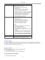
About Map Scale/Zoom
The "Zoom" control sets the scale of the map you are viewing. The scale is actually determined
by the type of camera lens and altitude in the case of Aerial Photography, the detail set for
scanning in the case of Topo Maps, and the desired enlargement in the case of Tiger maps.
The available scales are generally measured in "Meters per pixel", which effectively represents
the level of detail visible and the size the picture covers on the ground. The tiger map is
different, being continuously variable. The following shows the scales available:
Map Scales (Zoom)
Map Type
Aerial
1 Meters/pixel
2 Meters/pixel
4 Meters/pixel
8 Meters/pixel
x
x
x
x
x
x
x
Topo
Tiger
Varies continuously
p39
© AMC Inc 2004
-o-
About using the maps in AutoCAD
We knew you'd be interested in this, so we want to answer it. You can save the Aerial, Topo,
and Tiger maps to an image file, and that file can be imported into AutoCAD. However the
image will not be scaled properly, and you will have to change the image to the proper scale.
This is not particularly easy. You must find known points on the map, measure the distance in
(ACAD units) between them, and compare it to their actual distance. Then adjust the map size
to match by changing the scale of it's insertion.
You can also plot the points from the grid into AutoCAD, and try scaling and aligning the bitmap
to line up with the plotted points.
If this is done carefully, you can come up with a fair resemblance of the map image at true scale
in AutoCAD. However the quality of the image may degrade, depending on how much it is
scaled.
-o-
Real Time Capture
Capturing Points
One of the great features in GPS2CAD is it's ability to capture the GPS points at a pre-set
interval, and save the points to the point grid, to AutoCAD, or to a Microsoft Access 2000
database.
To use the Real Time Capture, first make a connection to the GPS unit, then click on the toolbar
button "Real Time" or the drop down menu item:
The Real Time Capture window will appear:
p40
© AMC Inc 2004
Provide the requested information:
Interval in minutes - enter the desired interval in minutes (or decimal fractions) that you
want to capture the GPS points
Default Name - enter a default name to use
Auto Increment Name - checking this box will automatically add a consecutive number to
the end of the Name. In most cases, leave this checked
Default symbol - select the symbol to assign to the captured point. If you're not sure, select
"Waypoint"
Add To Grid - If you want the point to be added (appended) to the current grid, check this
box. The point will appear with the coordinate translations and other information
Add To ACAD If you want to add the points to Your AutoCAD drawing, make sure to start
AutoCAD and begin a drawing. Select the items you want to plot. Plotting points and blocks
will provide the same results as plotting from the main grid. However plotting lines will
product line segments, not Lightweight polylines. If you want them as a continuous line, you
p41
© AMC Inc 2004
must convert them to a joined polyline in AutoCAD
* ACAD Zoom Extents after every point
* ACAD Regen after every point
These two settings are designed to make it easier when capturing and plotting into ACAD on
short
time intervals. On occasion, you may be capturing points within seconds of each
other, and place
a heavy load on AutoCAD's ability to keep up with the zooms and
regens. If this becomes a
problem, try unchecking these selections until you find a
combination of zooms -regens - capture
interval that works for your setup.
Add to Access - this adds a points to an Access 2000 database. If you want to start a new
database, click File New, and if you want to append to an existing database, click File Open.
Note that the existing database has a specific structure and must have been created using
GPS2CAD. There is a special section on capturing on Access here.
Once these selections are made, click Begin to start the capture.
The start button will switch to a pause button. Click pause if you need to temporarily pause the
capture, or Cancel to stop completely.
Here are a few tips about using this feature:
You can add points to Grid, ACAD, and Access all at once if you want, or any combination of the
three.
Try plotting lines in AutoCAD with a very short capture interval (i.e. 0.1 min) and switch to
AutoCAD to watch the line grow. If you are stationary at your desk, the resulting plot shows the
accuracy of your GPS unit - the shorter the lines, the more accurate.
-o-
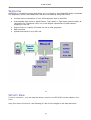
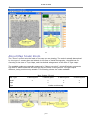
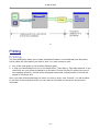
To Access
The program will capture points and place them into an Access 2000 database. This gives you the potential of
writing an application that reads this information as it comes in and processing it as you need to. Note however
that there may be some concurrency issues in multi-user access to the database.
The database is opened with a dynamic recordset, which provides a live view of the data. But the application
that consumes this data must perform a periodic requery of the database to see the changes. An Illustration of
Real Time Capture to a database:
p42
© AMC Inc 2004
-o-
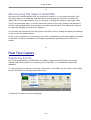
Printing
Printing
The Print dialog box allows you to place selected information on the finished print document,
and to select the information you wish to print. You may choose to print:
Any of the main grids or the Direction Distance grids
A map you have saved from one of the Aerial Photo, Topo Map, or Tiger Map windows. If you
check this box you will be prompted for a file name. Choose the file you saved from one of
the mapping windows; the file name will appear below and a small preview of the file will
appear in the larger box.
Once you have finished selecting the items you wish to print, click "Preview". You will be taken
to the Print Preview window where you can make a final check on the layout and print the
document.
p43
© AMC Inc 2004
-o-
Print Preview
The print preview window allows you to view the documents you are about to print, and either
continue printing or cancel. The controls on this page are simple:
Page slider bar lets you switch to multiple pages
Zoom - lets you zoom in and out as necessary
Cancel - cancels the print job
Print - Prints the document
p44
© AMC Inc 2004
-o-
Print Setup
This is a standard Windows Print setup box. Review the settings before printing.
p45
© AMC Inc 2004
-o-
Importing and Exporting data
Introduction
Beginning with GPS2CAD Version 3.5, a new Import/Export "Engine" is provided. This feature
allows far greater flexibility and compatibility with other sources of data.
Importing Points:
AutoCAD - this is an upgraded feature from earlier versions of GPS2CAD. It allows you to
import points from the AutoCAD drawing that is currently running into the main grid. From
here they can be uploaded to the GPS unit or viewed on the maps.
Garmin's MapSource program - This popular program is frequently distributed with their GPS
units, or is available separately. GPS2CAD will import files that are EXPORTED from this
program (not their saved project files)
Magellan's MapSend program - This program is available from Magellan and is used to
manage waypoints and maps. GPS2CAD will import files that are EXPORTED from this
program (not their saved project files)
Other sources - A complete import "Wizard" is provided to work with generic text files that
are created by many other industry standard programs.
Exporting Points:
.dxf - The most popular format for exchanging data between programs. Using this will allow
you to use GPS2CAD with many other programs such as AutoCAD LT., IntelliCad, TurboCAD,
and others
p46
© AMC Inc 2004
Access 2000 Database - points are exported in a .mdb file
Text File - comma or tab delimited text files can be exported
-o-
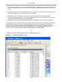
Importing Points FROM AutoCAD
Points can be uploaded from AutoCAD to GPS2CAD by following this procedure:
Open the AutoCAD drawing, switch back to GPS2CAD
Go to File/Import Points/ACAD Points
Read the Import Information box, and click OK
The following window appears:
p47
© AMC Inc 2004
Enter the ZONE that the points are in. You must know this in advance in order to import the
points. If you choose the wrong zone, the resulting Latitude/Longitude translation will be
incorrect.
If you do not know what zone you are in, and the points are near to your current location,
you may get the zone by setting your GPS to read out in the same UTM system, and checking
the zone that is displayed - but only if the points are in the same zone that your GPS is in.
Select the Grid to import the points into. If you choose the Route grid, you may need to add
a route header (the dark blue grid line that has the name of the route). You can do this by
clicking the Add Header button, and supplying the requested information
You should be taken to the AutoCAD drawing with a selection cursor active
Select the Lightweight Polyline, points, or blocks to upload. In the case of a polyline, it does
not matter which end you select - the veritcies will be entered only one way.
The points will be placed into the selected grid.
Note that it is important to understand the following :
1. If you select one of the UTM datums, you must supply the Zone that the points are plotted
p48
© AMC Inc 2004
in. In order to make the correct coordinate calculation, GPS2CAD must know what Zone the
ACAD coordinates refer to, and there is no information maintained in AutoCAD that can be
used.
2. When uploading points from AutoCAD, you must select the SAME DATUM that they were
originally plotted in. For example, you CAN'T DO THIS:
Download points from GPS into a Grid with the project Datum set to UTM_NAD27
Plot the points into AutoCAD. They will be plotted based on the coordinates shown on the
grid and the Datum Selected when downloaded
Upload the points from AutoCAD and SELECT A DIFFERENT DATUM THAN UTM_NAD27
Normally during a working session, this mistake would not be made. The real risk occurs when
the drawing is saved, and then re-opened another time, with a new session of GPS2CAD
running. There will be no indication in ACAD what datum the points are plotted in, and the
DATUM running in GPS2CAD MAY HAVE CHANGED. If you try uploading the points from
AutoCAD, the resulting Latitude/Longitude calculations WILL BE WRONG!
-o-
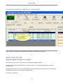
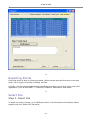
Importing from Garmin's MapSource
Step 1: Inside MapSource
p49
© AMC Inc 2004
Download the points into the program
Select the Waypoints tab to view the waypoints
From the drop down menu select Edit\Preferences\ Units tab; Set the Altitude/Elevation box
to Feet, and the Distance & Speed to Statute.
The distance and speed setting in MapSource is not used because only latitude and longitude
values are imported to GPS2CAD.
From the Position tab, select Grid: Lat/Long hddd.ddddd, and Datum: WGS 84
p50
© AMC Inc 2004
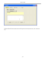
Go to File/Export. Choose Tab Delimited/ *.txt file and supply a name. Click ok to save
p51
© AMC Inc 2004
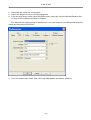
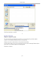
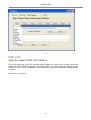
Step 2: Inside GPS2CAD
Go to the File/Preferences/Grid and Units tab and set the Units to INT_FOOT
Select the Datum you want the points translated to. Save and Close Preferences
Go to File/Import Points/Garmin MapSource, click
Review the information in the next window, click OK
Select the file, click OK to import
The points are now in the main grid and can be used as any GPS points.
-o-
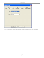
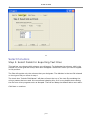
Importing from Magellan's MapSend
To import a Magellan Waypoint/Route file follow this procedure:
Step 1: Inside MapSend
When working with Waypoints:
Go to Waypoints\Export
p52
© AMC Inc 2004
Enter the File Name
Select Waypoints/Routes Files (*.txt)
Click Save
Select this file for import to GPS2CAD
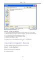
When working with Tracks:
Go to Tracks/Export
p53
© AMC Inc 2004
Select this file for import to GPS2CAD
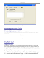
Step 2: Inside GPS2CAD
Go to File/Import Points/Magellan MapSend/Waypoints and Routes {or} Tracks
View the Information Window, click OK
Select the File you exported from MapSend
The files are imported to the main grid
p54
© AMC Inc 2004
-o-
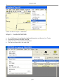
Importing from Other
The "Other" selection begins the Import wizard, designed to import points from a jvariety of text
files or an Access 2000 database file. The wizard is straight forward, containing 8 disticnt steps.
There are many helps along the way to make the import easier.
-o-
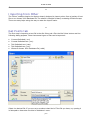
Get Points tab
The first step in importing a text file is the Get Points tab. Click the Get Points button and the
following dialog appears. Note that several types of files can be imported:
Comma Delimited (.csv)
Comma Delimited text (.txt)
Tab Delimited text (.tab)
Tab Delimited text (.txt)
Microsoft Access 2000 Database file (.mdb)
Select the desired file. If you are not sure about what kind of Text file you have, try opening it
in Notepad to determine the kind of delimiters it uses.
p55
© AMC Inc 2004
Once you open the file, the main import grid is populated with them information, one line at a
time. From this point on, the type of file delimiter you selected does not matter.
The path to the file is displayed in the label below the grid. This is only for reference during the
process.
There is no practical limit to the number of points that can be inserted from the import file.
Click the NEXT button to continue.
-o-
Type of Points tab
Step 2 - Choose the type of points
The wizard does not yet know what kind of points you are importing, so you must tell it on this
tab. Two kinds can be imported:
p56
© AMC Inc 2004
Lat/Long points - if the text file contains the point location in DECIMAL latitude and longitude,
select this. When you choose this, you must also tell the wizard what units the altitude are in
(for the incoming file); make this selection
UTM or State Plane Coordinates - if the points are in an XYZ system, make this selection.
Notes:
1. When importing Lat/Long points, they MUST be in Decimal Degrees. If they are not, and
the program that generated the file can not export them in this format, you may be able to
put them into an Excel spreadsheet, and have a column formula that creates the decimal
degrees, then re-export the file. Future editions of GPS2CAD will expand this units selection.
2. You may have a text file that has Lat/Long AND XYZ formats. In this case, simply choose
which one that you want to use.
3. Since you can have points in Lat/Long or XYZ format, this can become a "batch convert"
from one datum to another.
4. Note the text box at the bottom that provides feedback as you continue through the wizard.
-o-
p57
© AMC Inc 2004
Datum Selection tab
Step 2 Select Datum / Grid for Import points
On this tab you tell the wizard what datum the incoming points are in. The selection box
resembles the same one as in the Preferences window, with one major difference. If you
selected Lat/Long point type in Step 2, you will see only Lat/Long datums to choose from. If you
selected UTM/State Plane points, the box will have only these datums to choose from.
Select the datum and click Next to continue
-o-
Zone Selection tab
Zone Selection - If you selected UTM / State Plane points in Step 2, you must tell the wizard
what zone these points are in. Even if the zone is contained in the text file, you must make the
selection manually at this point.
You must also tell the wizard what units the grid is in.
If you chose a State Plane coordinate system in Step 3, the Zone designated is implicit in the
p58
© AMC Inc 2004
selection you made. The Zone selection box will be disabled.
Notes:
1. All the points must be in the SAME zone.
2. Only Numeric Zone designations are used. If there is a letter designator with the zone,
ignore it.
-o-
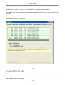
Column Assignments tab
Step 4 - Required Assignments
This tab is the real "work horse" of the import process and the point at which you tell the wizard
what each column of the file contains. Based on the type of file you are importing and the
selections you have made so far, the color coded labels show which column assignments you
need to make. A red label indicates you MUST make that designation, a yellow label indicates
that selection is Optional, and a green label indicates it has been made correctly.
It is at this point where you can "weed out" columns you don't need, by setting them to
p59
© AMC Inc 2004
"Not_Used".
The Column Assignment window as you begin:
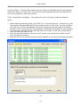
To designate what each column contains, click in each cell of the top, dark green grid row. A
drop down box will appear, and you can scroll to designate what that column contains. Note that
the columns default to Not_Used. You need only make the designations indicated by the color
coding, and as you make them the required assignments label will turn green
Making a column selection:
p60
© AMC Inc 2004
The column assignment window with all the selections made:
p61
© AMC Inc 2004
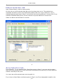
Insert Custom Info
In some situations you may need to overwrite (or supply) custom information into the text file.
This control will allow you to place this information into the grid. The information will be place in
all the rows in the grid (i.e. you can't place it in only some points) A good example of this would
be to make a Symbol designation for all the points.
To
1.
2.
3.
use this control,
Select the Column the information will be place into
Type the custom information into the text box below
Click Insert Info., and the information will be written into the grid.
p62
© AMC Inc 2004
Save Column Settings, Get Column Settings
Frequently you will be working with just one type of import file, and the column settings will be
the same every time. This control allows you to reuse these settings.
Once you make the first Column Assignments, you can save them to a .set file. To use them
again, just click the Get Column Settings button and select the file. The column assignments will
be made automatically, and all the required text boxes should turn green.
-o-
Grid Selection tab
Step 5 Select Grid to Import to
Yes, there's a typo error. The frame should read "Step 5".
In this tab you tell the wizard where to put the points in the main grid. In most cases they will
go into the waypoint grid, however you may also put them into the Route or Track grid.
p63
© AMC Inc 2004
If you place them into the Route or Track grid, you may need to add a route or track header row
to the grid that is the target of the import. You may do so by clicking the "Add Route Header" or
"Add Track Header" button.
p64
© AMC Inc 2004
This picture illustrates what a "Header Row" is in the main grid
Once you have supplied the necessary information, click Next to continue.
-o-
Select Points tab
Step 6 Select Points to Import
Yes, there's a Typo error. The frame in the window should be Step 6
On this tab you select which points or rows to import. You may click and drag, or use the
selection box.
IMPORTANT NOTE! It is at this point where you can de-select rows that do not contain valid
point data. Import only rows that are valid points!
Click Next to continue.
p65
© AMC Inc 2004
-o-
Verify and Import tab
Step 7 and 8 - Verify Input and Import Points
The last tab in the wizard requires you to verify the input you have made. The Import points
button will not be enabled until the text box reads "OK to Import", indicting it has passed the
Verify test.
The Verify Input button performs several checks to validate the choices you have made, and the
integrity of the data. If it finds an error, you will see a message in the text box describing the
error and it's location. Return to that point in the wizard to correct it, and try the Verify button
again.
Once the Import Points button is enabled, you can click it to import the points (Finally!). Return
to the main program window to view the points that have been imported.
p66
© AMC Inc 2004
-o-
Exporting Points
Exporting points is done in a five step wizard. Points may be exported from any of the main
grids, into a variety of formats, including .dxf files.
DXF files are the interchangable format that allows your data to be used in many other CAD
applications, such as AutoCAD LT, TurboCAD, IntelliCAD, Microstation, and others.
-o-
Select File
Step 1: Select File
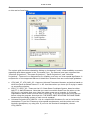
To begin the export process, go to File/Export Points. The first window of the Export wizard
appears with the "Select File" tab active.
p67
© AMC Inc 2004
Click the Select File button and choose the file type from the drop down box, then select the
file:
p68
© AMC Inc 2004
Click Save, then Next to continue.
-o-
Select Points
Step 2: Select Points
The second tab lets you designate the grid that you are exporting from, and then make a
selection of the individual rows/points that you are exporting.
Selection may also be made directly on the grid by click and drag.
Do NOT export header rows if you are exporting from the routes or tracks grid. Select only the
point rows. If you select a header row it will be ignored.
Click Next to continue.
p69
© AMC Inc 2004
-o-
Select Columns
Step 3: Select Fields for Exporting Text Files
This tab lets you choose which columns you will export. To designate the columns, click in the
second row of the grid and a drop down box will appear. Select the Column you wish to appear
in this position.
The files will contain only the columns that you designate. The delimiter in the text file is based
on the type of file you chose in step 1.
The check box "Include Field Names" will place a line at the top of the text file containing the
column names that are used. We recommend selecting this, as it is very helpful when viewing
the file from other programs such as Notepad. The line can always be deleted with a text editor.
Click Next to continue.
p70
© AMC Inc 2004
-o-
DXF Info
Step 3a: Select DXF Information
If you are exporting a DXF file, this tab will be enabled. It is here that you may choose the
additional DXF information required by CAD programs. You may export the data as points,
blocks, or lines, or any combination. The Layer, color, and Font information should also be
selected.
Click Next to continue.
p71
© AMC Inc 2004
-o-
Export
Steps 4 and 5: Verify Settings and Export Points
This is the last tab in the Export wizard. First click the Verify Settings button to insure that you
have supplied all the necessary information.
If there is a problem with the input information, you will be given a notice and location in the
text box.
Once this test is passed, the Export Points button will be enabled.
p72
© AMC Inc 2004
-o-
Knowledgebase and FAQ's
Knowledgebase and FAQ's
Knowledge base and FAQ's are maintained on the GPS2CAD website so they can be
kept current.
Click Here
-o-
The FUN Stuff
FUN Activites
Geocaching: "Geocaching" is one of the new outdoor sports that has grown up around GPS
units. It is essentially a GPS style treasure hunt, where your GPS unit is used to guide you to
the cache. Actually, it's quite fun, and great reason to get outdoors, and play with your "toys".
Naturally, a whole community has grown up on the Net, and probably the most common one is
www.Geocaching.com.
The "Degree Confluence Project": Confluence.org: Somewhere along the way people began
to wonder "What's at 32 deg.N/-112degW" - or something like that. The effort is to photograph
all the even degree Latitude/Longitude locations on earth. Confluence.org is a website where
this is conducted, and the photographs are posted. If you want to participate, pick an even
p73
© AMC Inc 2004
Lat/Long locations, use your GPS to go there, photograph it, (along with your GPS unit for
proof), and send it in!
There are of course many other activities for having fun with your GPS and your copy of
GPS2CAD. We'd love to hear from you!
-o-
The OTHER Stuff
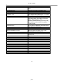
GPS2CAD Supported Projections
Supported Grids (Map Projections)
American Projections
UTM based on NAD_27
UTM_NAD_27
UTM based on NAD_83
UTM_NAD_83
SPCS 27 - State Plane Coordinate System from
1927. Based on the NAD_27 datum.
SPCS_27
SPCS 83 - State Plane Coordinate System from
1983. Based on the NAD_83 datum.
SPCS_83
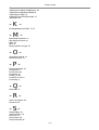
European Projections
Austria
Bundesmeldenetz (BMN).
AUSTRIAN_GRID_M28
AUSTRIAN_GRID_M31
AUSTRIAN_GRID_M34
Dutch
Rijksdriehoekstelse (RD) based on the
AMERSFOORT datum
DUTCH_GRID
Finnish
Kartastokoordinaattijärjestelmä, KKJ. Based in the FINNISH_GRID_ZONE_1
FINNISH_GRID_ZONE_2
FINLAND_HAYFORD datum.
FINNISH_GRID_ZONE_3
FINNISH_GRID_ZONE_4
French
Lambert (NTF)
FRENCH_GRID_ZONE_1
FRENCH_GRID_ZONE_2
FRENCH_GRID_ZONE_3
FRENCH_GRID_ZONE_4
FRENCH_GRID_ZONE_2_ETENDU
FRENCH_GRID_GRAND_CHAMP
Lambert 93 (RGF93).
FRENCH_GRID_RGF_93
Germany
Deutsches Haupt Dreiecks Netz, DHDN (Potsdam) DHDN
Italy
Gauss-Boaga. Based on the ROME_40 datum
ITALIAN_GRID_ZONE_1
ITALIAN_GRID_ZONE_2
Luxembourg
Based on the LUREF datum.
LUXEMBOURG_GRID
p74
© AMC Inc 2004
Norway
Based on the NGO_48 datum
NORWEGIAN_GRID_ZONE_1
NORWEGIAN_GRID_ZONE_2
NORWEGIAN_GRID_ZONE_3
NORWEGIAN_GRID_ZONE_4
NORWEGIAN_GRID_ZONE_5
NORWEGIAN_GRID_ZONE_6
NORWEGIAN_GRID_ZONE_7
NORWEGIAN_GRID_ZONE_8
Belgium
Belge Lambert 1972.
BELGIUM_GRIDBELGIUM_GRID
Britain
British National Grid, BNG Based on the OSGB_36
BRITISH_GRID
datum.
Ireland
Irish Grid. Based in the IRELAND_65 datum.
Sweden
Swedish Grid, Rikets Nät (2.5 gon V). Based on the
SWEDISH_GRID
RT90 datum.
Swiss
Swiss Grid. Based on the CH1903 datum.
IRISH_GRID
SWISS_GRID
SWISS_GRID_LV95
Pacific Projections
Australia
Australian Map Grid (AMG 84) based on the
AGD_84 datum (improved version of AGD 66).
UTM_AMG_84
Map Grid Australia (MGA 94) based on the
geocentric GDA_94 datum. The difference to AMG 84 UTM_MGA_94
is about 200 meters.
New Zealand
New Zealand Map Grid (NZMG) based on the
NZGD_49 datum NZM G
NZMG
New Zealnd Transverse Mercator (NZTM) based on
NZTM
the NZGD_2000 datum.
Universal Projections
Universal Transverse Mercator (UTM) is a global
grid (coordinate system) designed to work
everywhere except at the poles. It contains
coordinates and a Zone designation
UTM based on WGS_84 for the northern hemisphere UTM_NORTH
UTM based on WGS_84 for the southern hemisphere UTM_SOUTH
UTM based on ETRS_89. Used in Europe.
UTM_ETRS_89
UTM based on ED_50. Older system used in Europe. UTM_ED_50
-o-
Other Resources
Here are some related links you may find helpfule:
U. S. Geological Survey
The Grandaddy of Map sites
p75
© AMC Inc 2004
TerraServer-USA
This is where GPS2CAD gets it's maps
from
Geocaching.com
The new, all-geek recreation site
Geodetic Datum Overview
A primer on Datums
Geoplace.com
"The authoritative Resource for Spatial
Information" ...their words
Geocomm.com
"The GeoCommunity™ is THE place for
the Geographic Information Systems
(GIS), CAD, Mapping, and
Location-Based industry professionals,
enthusiasts, and students to gather. "
...their words
GPSworld.com
An excellent magazine about all things
GPS. Online and printed.
Ordnance Survey
The British National GPS Network
National Geodetic Survey
Not the same as USGS, but a very
interesting Government site.
U.S. Census Bureau
This is where GPS2CAD's Tiger maps
come from
Trails.com
A great outdoor site
-o-
p76
© AMC Inc 2004
Index
-AAbout Map Scale/Zoom 39
About using the maps in AutoCAD 40
ACAD Settings 12
Add Points 37
-CColumn Assignments tab 59
Connecting to GPS 14
-DDatum Selection tab 58
Deleting points on Map 38
Downloading Points and Routes 16
DXF Info 71
-EExport 72
Exporting Points 67
-FFeatures 8
FUN Activites 73
-GGet Points tab 55
Getting Points from AutoCAD 25
GPS Units 11
GPS2CAD Supported Projections 74
Grid Columns 18
Grid Selection tab 63
Grids and Units 9
-IImporting and Exporting data 46
p77
© AMC Inc 2004
Importing from Garmin's MapSource 49
Importing from Magellan's MapSend
Importing from Other 55
Importing Points FROM AutoCAD 47
Introduction 46
-KKnowledgebase and FAQ's 73, 73
-MMain Window Controls 21
Map Window Controls 31
Maps 28
Misc 12
Moving Points in the grid 27
-OOpen/Save Projects 14
Other Resources 75
-PPoints and Routes 25
Preferences 9
Print Preview 44
Print Setup 45
Printing 43, 43
Purchase On Line 6
Purchasing 6
-QQuick Start 4
-RReal Time Capture 40
Round-off 23
-SSample Maps 28
Select Columns 70
Select File 67
Select Points 69
Select Points tab 65
p78
© AMC Inc 2004
Sending Points TO AutoCAD 24
Sorting Points 20
Splash Screen 13
-TTour 7
Type of Points tab 56
-UUpgrading 6
Using the Preview Map 33
-VVerify and Import tab 66
Video Help 4
-WWelcome 3
What's New 3
Working with AutoCAD 24
-ZZone Selection tab 58
p79
© AMC Inc 2004
p80
© AMC Inc, 2004
www.AzTechSoft.com