1
University of Southern Queensland
Faculty of Engineering and Surveying
Educational Robot Design
A dissertation submitted by
Matthew Darrell Bishop
In fulfilment of the requirements of
Course ENG4111 and 4112 Research Project
Towards the Degree of
Bachelor of Mechatronics
Submitted: January 4,2007
Abstract
By introducing children, in the final years of primary school, to simple
Engineering principles, children may consider Engineering, when they make the choice
of career, in the early years of high school.
Using a Robot, as this vehicle, ties the already existing fascination children have
with science fiction to a practical classroom interaction. This interaction should
effectively draw attention to Engineering and create interest in the disciplines it
encompasses. The exposure of children to Engineering, in this intimate format, should
help career choice and the growth of engineering in the future.
ii
iii
Certification
I certify that the ideas, designs and experimental work, results, analyses and
conclusions set out in this dissertation are entirely my own effort, except where
otherwise indicated and acknowledged.
I further certify that the work is original and has not been previously submitted
for assessment in any other course or institution, except where specifically
stated.
Matthew D. Bishop
Student Number: D9811486X
___________________________________________
Signature
___________________________________________
Date
iv
Acknowledgements
I would like to thank my wife, Hope, and my 3 children, Monika, Sarah and
Chloe for their support during my time studying.
Thanks must also go to my supervisor Mark Phythian and Frank Young.
Without your help this would never have come together.
v
Table of Contents
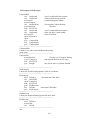
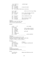
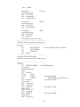
Table of Figures........................................................................................................ix
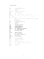
Glossary of Terms...................................................................................................... x
Chapter 1. Project Introduction ................................................................................ 11
1.1 Introduction....................................................................................................... 11
1.2 Research Objectives .......................................................................................... 11
1.3 Research with teacher and children.................................................................... 12
1.4 Conclusions: Chapter 1 ..................................................................................... 14
Chapter 2 Component Selection ............................................................................... 15
2.1 Position Sensor Selection .................................................................................. 15
2.1.1 Slotted Encoding wheel .............................................................................. 15
2.1.2 Gray Encoder wheel ................................................................................... 16
2.1.3 Rotary Encoder Potentiometer .................................................................... 17
2.1.4 Stepper Motor ............................................................................................ 18
2.1.5 Hall effect sensors ...................................................................................... 18
2.2 Motor Selection................................................................................................. 19
2.2.1 Stepper Motors ........................................................................................... 19
2.2.2 Servo motor................................................................................................ 19
2.2.3 Small DC motor and gear assembly ............................................................ 20
2.3 Electronic Compass Selection ........................................................................... 20
2.3.1 Dinsmore Digital Sensor 1490. ................................................................... 20
2.3.2 Dinsmore Analogue Sensor 1525................................................................ 21
2.3.3 Dinsmore Analogue Sensor 1655................................................................ 21
2.4 Motor circuitry Selection................................................................................... 21
2.4.1 H-Bridge .................................................................................................... 23
2.4.1.1 Standard transistors H-Bridge .............................................................. 23
2.4.1.2 Mosfet Transistor H-Bridge ................................................................. 23
2.4.1.3 H bridge Dedicated IC ......................................................................... 23
2.5 Microcontroller Selection .................................................................................. 24
2.5.1 PIC16f628A ............................................................................................... 24
2.5.2 PIC16F877A .............................................................................................. 25
2.6 LCD Selection................................................................................................... 26
2.7 Wireless Transmitting and Receiving ................................................................ 26
2.7.1 Infra Red Communication .......................................................................... 26
2.7.2 434 Hz UHF Wireless Communication....................................................... 27
Chapter 3. Chassis Material Selection and Design.................................................... 29
3.1 Chassis Type Selection...................................................................................... 29
3.2 Chassis Material Selection................................................................................. 29
3.2.1 CD Ply. ...................................................................................................... 29
3.2.2 Maranti pine. .............................................................................................. 30
3.2.3 Metal. ......................................................................................................... 30
3.2.4 Polypropylene ............................................................................................ 31
3.2.5 Final selection ............................................................................................ 31
3.3 Chassis Design .................................................................................................. 32
3.3.1 What is Assembly? ..................................................................................... 32
3.3.2 Printed Circuit Board Mounting.................................................................. 33
3.3.3 The Chassis and Drive Assembly................................................................ 34
3.3.4 Drive mounting .......................................................................................... 34
3.3.5 Steering ...................................................................................................... 35
3.3.6 Peripheral Mountings. ................................................................................ 36
Chapter 4. Electronics Design .................................................................................. 37
vi
4.1 Test Bed/Robot Main Board .................................................................................. 37
4.2 Line and light following Circuitry ..................................................................... 38
4.3 Compass Circuitry............................................................................................. 39
4.4 Hall effects circuitry.......................................................................................... 40
4.5 H Bridge Circuitry............................................................................................. 41
4.6 434 Hz Transmitter and Receiver ...................................................................... 41
4.7 LCD Module. .................................................................................................... 41
4.8 Stop Button Circuit ........................................................................................... 42
4.9 Connecting it together ....................................................................................... 42
Chapter 5. Software Consideration........................................................................... 43
5.1 Computer Software Programming ..................................................................... 43
5.2 The Computer Software .................................................................................... 43
5.2.1 Comm. Port set-up...................................................................................... 43
5.2.1 Robot ID Set-up ......................................................................................... 43
5.2.2 Main Menu................................................................................................. 44
5.2.3 Grid Points Dialog...................................................................................... 45
5.2.4 Compass Interface Dialog........................................................................... 46
5.2.5 Shapes Menu .............................................................................................. 47
5.2.6 Remote control ........................................................................................... 47
5.3 Interesting Aspects of the Computer code.......................................................... 48
5.3.1 The Communication Port code.................................................................... 48
5.3.2 The Grid Code............................................................................................ 48
5.3.3 The Compass code...................................................................................... 49
5.4 PIC16F877A Coding......................................................................................... 50
5.4.1 LDR Sensor Code....................................................................................... 50
5.4.2 Compass Coding ........................................................................................ 50
5.4.3 Grid following code.................................................................................... 51
5.4.4 Motor Codes............................................................................................... 52
5.4.5 Shapes Codes ............................................................................................. 52
5.4.6. Servo Interfacing ....................................................................................... 52
5.4.7 Port Interfacing........................................................................................... 53
5.4.8 Interrupt section.......................................................................................... 53
5.4.9 Sound Section ............................................................................................ 53
5.4.10 Remote Control ........................................................................................ 55
Chapter 6. Conclusion.............................................................................................. 57
6.1 Final Cost.......................................................................................................... 57
6.2 Achievement of Objectives ............................................................................... 58
6.3 Further Work..................................................................................................... 59
Bibliography ........................................................................................................ 61
APPENDIXES......................................................................................................... 62
Appendix A. Project Specification .......................................................................... 62
Appendix B. School Research ................................................................................. 63
Appendix C. Low Voltage In-System Programmer SCHEMATIC. ......................... 69
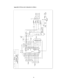
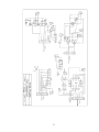
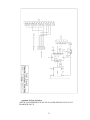
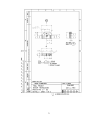
Appendix D. Electronic Schematics for Robot ........................................................ 70
Appendix E. Plans for Robot................................................................................... 72
Appendix F. Visual Basic Code Excerpts ................................................................ 80
F.1. Grid Coding (FrmAxis) ................................................................................ 80
F.2. Compass Coding (FrmCompass) .................................................................. 90
F.3. Active Comm. Port Find (FrmPORT)........................................................... 95
Appendix G. EEPROM Code.................................................................................. 97
Appendix H PIC16F877A code Excerpts ............................................................... 98
H.1. LDR ASM Code Excerpt............................................................................. 98
vii
H.2 Compass Code Excerpts ..................................................................................... 101
H3. Grid code Excerpt....................................................................................... 105
H.4. Motor Code Excerpt .................................................................................. 108
H.5. Shape Code Excerpt .................................................................................. 111
H.6. Servo Code Excerpt................................................................................... 115
H.7. Interrupt Code Excerpt .............................................................................. 117
H.8 Sound Code Excerpt ................................................................................... 121
viii
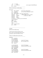
Table of Figures
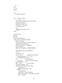
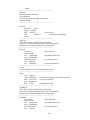
Figure 1: Brief Overview of Child Questionnaire........................................................ 13
Figure 2. 3-bit Gray Encoder Wheel (Rotary Encoder 2006) ....................................... 16
Figure 3. H Bridge simulation -Turning one direction ................................................. 22
Figure 4. H Bridge simulation -Changed direction ...................................................... 22
Figure 5. Simulated PWM Output............................................................................... 22
Figure 6. Transistor H-Bridge Circuit (The Complete BJT Circuit, 2006)................... 23
Figure 7. IR Transmission Angle ................................................................................ 27
Figure 8. Riser with slots ............................................................................................ 33
Figure 9. Drive Assembly ........................................................................................... 35
Figure 10. Assembled Robot with boards in situ ......................................................... 36
Figure 11. Pic16F87XA Pin out Diagram (Microchip, 2006b)..................................... 38
Figure 12. Picture of Mainboard ................................................................................. 38
Figure 13. LDR Circuitry............................................................................................ 39
Figure 14. Compass Board .......................................................................................... 39
Figure 15. Hall Effect Processing Board ..................................................................... 40
Figure 16. Hitachi 44780 LCD Pin out (Hitachi, 2006) ............................................... 41
Figure 17. Computer interface setting request dialog box ............................................ 43
Figure 18. Robot Number Dialog ................................................................................ 44
Figure 19. Main Menu Dialog..................................................................................... 44
Figure 20. Set Axis Option Dialog .............................................................................. 45
Figure 21. Grid Programming Dialog.......................................................................... 45
Figure 22. Compass Dialog......................................................................................... 46
Figure 23. Shapes Menu.............................................................................................. 47
Figure 24. Remote control menu ................................................................................. 47
Figure 25. RS232 Protocol Form (Kim, 2006)............................................................. 49
Figure 26. Binary Decimal Equivalents....................................................................... 49
Figure 27. Pic16F877A Register File Map (Microchip, 2006b) ................................... 52
Figure 28. Musical note, frequency and Timer0 settings compiled from (Physics of
Music – Notes, 2006) (Pic Timer 0 Calculator, 2006).......................................... 55
Figure 29. Hand Span Results ..................................................................................... 65
Figure 30. Questionnaire Participant Statistics ............................................................ 65
Figure 31. Movement.................................................................................................. 65
Figure 32. Assembly Time.......................................................................................... 66
Figure 33. Robot Appearance...................................................................................... 66
Figure 34. Robot Names ............................................................................................. 67
Figure 35. Children’s Robot Action Suggestions......................................................... 68
ix
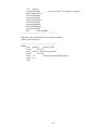
Glossary of Terms
ADC
AH
cm
Comm. Port
CPU
D.C.
DLL
EEPROM
FLASH
Power supply
Hz
I2C
IC
ICSP
I/O
IR
IrDa
LCD
LDR
LED
LVISP
LVP
ms
NPN
Opamp
OCX
OOP
O.S.
PCBoard
PNP
PWM
RAM
s
SPI
UART
µs
UHF
VREF
ZIF
- Analogue to Digital Converter
- Amp Hour
- centimetres
- Computer Communication Port
- Central Processing Unit
- Direct Current
- Dynamic Link Library
- Electronically Erasable Programmable Read-Only Memory
- Rewriteable computer memory that holds its content independent of
- Hertz
- Master slave option for connection of multiple microchips or intelligent
peripherals
- Integrated Circuit
- In Circuit Serial Programming
- Input/Output
- Infrared
- Infrared Data Association
- Liquid Crystal Display
- Light Dependant Resistor
- Light Emitting Diode
- Low Voltage In-System Programmer
- Low Voltage Programming
- milliseconds or 0.001s
- Operational Amplifier
- OLE Control Extension
- Object Orientated Programming
- Operating System
- Printed Circuit Board
- Pulse Width Modulation
- Random Access Memory
- second
- Serial Peripheral Interface
- Universal Asynchronous Receiver Transmitter
- micro seconds also can be designated us 0.000001s
- Ultra High Frequency
- Voltage Reference
- Zero Insert Force
x
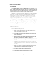
Chapter 1. Project Introduction
1.1 Introduction
As a child takes the rite of passage to adulthood there is an expectation, in our
society, that the child will make a life choice in the form of a career at the same time.
There are a plethora of choices for child, these days, and it is very difficult to expose
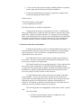
a child to a variety of career possibilities especially the more technical.
Engineering is a field that is in everyone’s daily life but is often overlooked as a
career choice. Providing a device that can bring engineering to the attention of
children, whilst entertaining and educating, will give children a taste for what
engineering has to offer in their future. This introduction could leave a lasting
impression that could help a future career choice when it is required.
This project is focused on bringing a robot design that can be readily used in the
Queensland teaching curriculum. The current curriculum is a results based plan that
allows the teacher a great deal of flexibility to incorporate tools, such as this, in a
custom-made teaching programme. By introducing relevant areas of the curriculum,
into its design, this project will be able to be adopted as a pertinent teaching tool.
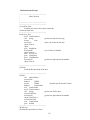
1.2 Research Objectives
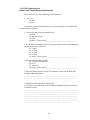
The main objectives of the project are:
a) Design, construct and commission a small robot suitable for use by
primary school students of grades 6 and 7.
b) Research the current school syllabus and teacher requirements so the
project will be relevant.
c) Obtain an overview of the children’s expectations of the project and
other aspects to make the project suitable for a child’s use.
d) Create the robot from low cost components so the final project costs less
than $150.
e) Build the robot from off-the-shelf components, where possible, so it
could be supplied in kit form and be assembled by a resourceful teacher
from plans.
f) Design robot structure, movement components and spatial awareness
components taking into consideration interchangeable parts.
g) Add functions including musical and tactile interface.
h) Create a computer interface for interaction with the robot.
11
i) Create relevant codes for the microchip including distance recognition,
motion, light and line following and spatial recognition.
j) Create relevant interfacing components to implement computer/robot
normal functioning and remote control.
If time permits:
- Research methods to shape plastic.
- Create a shaped plastic exterior.
The full specification is available in Appendix A.
Learning from observing is an excellent way to learn! Combining the
above specifications into a robot will allow the teacher to reinforce theory with
application. Using the icon based interface on a computer then activating the
robot, via the Wireless interface, will give real world applications for the child to
tie together with the theory they have previously learnt. These combinations
will allow this unit to become a valuable tool in the teaching environment.
1.3 Research with teacher and children.
It appeared obvious that any project, targeting children and teachers, was
doomed to failure unless the target users were consulted early in the planning
stage of the project. This was, therefore, an important first step and was
implemented early in the process.
The initial approach was to send a letter of outline to the principal of
local school. This was a requirement of the Department Of Education. From
here the relevant teacher was approached.
This initial research was a two-pronged approach. Firstly, input on what
the average teacher would require to integrate the finished product into the
everyday classroom situation was required. Secondly, the children needed to be
consulted as to what they might find useful and/or interesting if this sort of
device was going to be used, by them, in the classroom.
To implement the teacher stage of the project, an outline of questions
was put together. The idea was not to be too specific in case the tone and
expectations of the questioning skewed the outcome. By sticking to topics and
allowing the teacher to run with the ideas a plethora of information was
collected. This method, on reflection, took the interview far beyond what was
initially perceived as possible parameters for the project.
The following points were highlighted as useful from a teacher’s point of
view.
The robot should:
•
Be able to generate shapes (squares, rectangles etc.) and
demonstrated areas and perimeters.
12
•
Be able to operate on a coordinate system to demonstrate
graphing.
•
Have the ability to draw a picture from the coordinate system.
•
Be able to demonstrate basic compass navigation.
•
Have an LCD screen for output to take the children away from
the computer after the initial programming; and
•
Possibly offer some sort of challenge.
It was also discovered, from the interview; that a child could concentrate
for up to an hour so the robot tasks could be reasonably involved. It would also
be possible to incorporate building the robot as a lesson in itself. A copy of the
current teaching curriculum was shared with relevant sections highlighted. It
showed many areas where the robot would be useful and easily integrated into
the classroom environment.
The child-orientated section of the data collection was in the form of a
statistical information collection and a questionnaire for the children. The
teacher who was approached had experience in the area of child questionnaires
and ethics. After reviewing the proposed questionnaires, he considered them to
fit within the requirements of ethics. To maintain the ethical approach the
children’s questionnaires were conducted as a class activity without the author
being present.
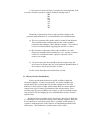
The first part of the child’s questionnaire (Appendix B (a)) came about
on the idea that the robot might be assembled from a group of modular boards
that could become a class activity in itself. It involved measuring the hand span
of each child so that an average or, as was eventually chosen, the smallest hand
size could be found. The results show that by making the boards a maximum of
75mm, on the small side, it would allow all children of this age group to
comfortably grip the boards and assemble them.
The questionnaire (Appendix B (b)) was incorporated to see what the
children thought would be interesting or useful. The questions were meant to be
slightly leading to narrow the field off possible answers. Unfortunately, as W.
C. Fields indicated, “never work with children or animals”, so, the questions
lead to some interesting answers. A full rundown can be found in Appendix
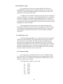
B(c). A summary of the answers is included below.
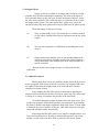
This research greatly helped set the project specification.
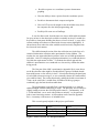
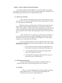
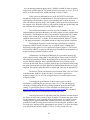
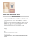
Topic
Motion
Time to Assemble
Appearance
Girls%
Walking 56%
More then 30 mins 50%
Sci-fi robot 57%
Figure 1: Brief Overview of Child Questionnaire
13
Boys%
Wheeled 28.5%
30 mins 38%
Sci-fi robot 31.3%
1.4 Conclusions: Chapter 1
As any parent knows, cost is a real factor in today’s “free” education. In the
long run parents, through organizations like the P & C (Parents and Citizens
Association), supply the money to purchase many of the learning aids that children
use in school. Parents want their children to have an education that includes learning
with technology-based influences, to prepare them for the future. They know they
that this helps create steppingstones for future education choices for the changing
world that will be our children’s. By providing the above system, while keeping that
the system costs down, the real outcome of this project will be a system that can be
used in modern schools.
Using the data collected from the questionnaire the project direction was
chosen
14
Chapter 2 Component Selection
An important aspect of the project involved finding cheap and effective
ways to implement the mechanical requirements of the Robot. This section will discuss
this aspect of the project. Earlier on in the project consideration was given to the size of
the final product and ideally for several reasons focus would be put into keeping it
small. This consideration was kept foremost in mind, along with price, when
considering below.
2.1 Position Sensor Selection
Position sensing offered its own unique challenges. It had to be kept in mind
that non-technical people could possibly assemble the Robot, if a kit was developed.
Special consideration was therefore required to find the easiest method to enact the
position sensing whilst keeping in mind the skill requirement involved. The
following systems were considered:
2.1.1 Slotted Encoding wheel
The encoder wheel is commonly used for this style of application. The
principles behind its use are very simple. Historically, this style of sensing
incorporates a wheel with slots cut at regular intervals around its circumference, a
light emitting diode, often infrared, and a matching sensor. As the wheel turns,
while the robot is moving, it causes the light beam to be interrupted. The related
circuitry converts this to a pulse that can be sent to the microcontroller. This sort
of encoding wheel is very often used in computer mouses, the variety with a ball
that contacts the mouse pad, where accuracy and small movement detection are
required.
The main drawback for this situation comes in the size of the encoder
wheel itself. Because of the size constraints underneath the robot this encoder
wheel would have to be less than 20 mm diameter.
The simplest way to get a precision wheel, of this size, would have been
to purchase a cheap mouse and use the wheels and circuitry from this to enact the
system. While this was considered, two objections came against it
(a) Cheap mice seem to be imported in lots and once they are all sold the
next lot are of different design. It is possible the changes in design
may make them incompatible with the final robot design.
(b) The design of the encoder wheel incorporates a shaft that actually
contacts the ball of the mouse. This usually clips at either end to give
the unit stability so the movement interaction can take place. The
modification of the encoding wheel for incorporation into the robot
was less then satisfactory.
15
Another way to access this style of sensing would be to manufacture the
encoding wheel .The manufacture of an accurate encoder of this diameter could be
done by:
(a)
(b)
(c)
Cutting from a thin soft material that could be cut with a Stanley
knife or a fine cutting implement.
Cutting using a precision cutter e.g. a laser cutter from a thicker piece
of material.
Injecting or moulding in plastic by a plastics manufacturer.
The first method is not satisfactory when used in a situation where users,
in this case children, could possibly touch or otherwise manipulate the sensor
wheel as material fine enough to be cut in this way would be flimsy at best. The
method of manufacture is also dangerous and not conducive to producing an
accurate final product.
The second method of manufacture is ideal for small run production like
this and would create an extremely accurate product. Unfortunately it is quite
expensive and has to be done with an expensive precision cutter.
Realistically this unit will be at best a small run production. Having the
dies struck to make an encoder wheel by injection or moulding as in (c) is very
expensive. The savings on these methods come as large quantities are produced
and the cost is shared out among a multitude of items. Though this is the ideal
method to produce this sort of precision item, the cost prohibits this.
This style of position sensing was therefore rejected.
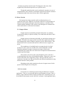
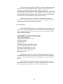
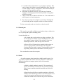
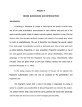
2.1.2 Gray Encoder wheel
The Gray encoder wheel is a particularly simple design where a wheel is
marked with shaded and white areas of various lengths circumferentially around a
circle. The current position, in relation to the sensor, is determined by an optical
sensor array detecting the light or dark areas underneath. By having three or four
senses in alignment, the current position is output as a binary sequence depending
on these areas underneath.
Figure 2. 3-bit Gray Encoder Wheel (Rotary Encoder 2006)
16
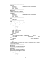
A 3 bit encoder as shown in Figure 2 produces the following binary code
as it turns clockwise (you move counter clockwise) starting at the ⊕
000
001
011
010
110
111
101
100
Though this is particularly effective with a position sensing, in this
particular application there are several difficulties in its implementation.
(a) The size constraint of the encoder wheel is around 20 mm diameter.
This would mean that each particular encoder section would be
particularly fine making it a little difficult to produce. This could of
course be worked around by supplying the encoder as a sticker.
(b) The electronic componentry of the reader would be very small.
Electronics miniaturisation is obtained at a cost. An array of sensors
of this size would become quite expensive especially if more
accuracy was sought.
(c) To gain accuracy the wheel would need more encoder rings and
more sensors to decipher the Gray code produced. Miniaturisation of
the electronic sensors again becomes an issue
For the reasons listed above this method was rejected.
2.1.3 Rotary Encoder Potentiometer
Rotary encoder potentiometers are readily available at high-end
electronics suppliers. A rotary encoder works, in a similar method to the
encoder wheel above, often in the Gray encoder configuration. The main
difference is that, in place of light, metal contacts brush on contact and noncontact areas to give a binary representation of the current position. These
encoders range in price according to the accuracy or style of encoding starting
from as little as $10 and ranging up to several hundred for the more accurate
optical variety.
Besides the obvious problem of price for accuracy, this style of device has
it’s own unique issues in regards to incorporation into this designed. While the
devices themselves can be quite small, there is a problem in this instance in
regards to mounting because of the closeness of surrounding mechanical and
chassis parts. This method was rejected because of these issues.
17
2.1.4 Stepper Motor
Stepper motors are available in all shapes and sizes and are readily
available from old office and computer equipment. The most useful aspect of
these particular motors is they can move in small increments of degrees. Power
has to be sent to particular coils, within the motor, in a particular order to make
the Stepper motor operate. This order means that it is quite easy to track the
current position of the motor and how far it has travelled since the pulses started.
The disadvantages of this style of motor:
(a)
They are rather bulky in size. This means the size of wheels needed
for the vehicle would be fairly large to compensate for the size of the
stepper.
(b)
This size also means there are difficulties in mounting them to the
chassis.
(c)
Stepper motors have multiple wires in each unit depending on the
amount of steps that are available from the unit. Connecting these
units would require either multiple pins on the Microcontroller or a
specific controller.
Because of these issues Stepper motors were discounted for this
application.
2.1.5 Hall effect sensors
Modern Hall effect sensors are commonly used to detect the presence of
metal or magnetic fields. Some models are so sensitive, to magnetic fields, they
are capable of detecting the magnet fields of the earth and most electronic
compasses are based on these.
In this instance the Hall effect sensors would work by detecting the
magnetic fields created by the presence of teeth on a metal cog. The sensor emits
a voltage or no voltage in relation to the presence of the metal teeth.
To facilitate detection a magnet is glued to the back of the sensor. This
produces the magnetic field with the presence of a metal tooth. By positioning
the North or South of the magnet, against the back of the sensor, it can be made
to detect the presence of metal or its absence. Hall affect sensors are also quite
cheap and reasonable robust electronically.
Surprisingly the Hall effect sensors were sensitive enough to detect very
fine teeth on small sprocket. By using a small metallic sprocket, with a large
number of teeth, on the main drive shaft, connected to the wheels, minute
18
variations in position can be detected. This happens as the teeth, of the
magnetically effected metal sprocket, move past the sensor.
Though this method worked out to be moderately expensive, its ease of
implementation, in this situation, and minimal requirement of skill for inclusion
or adjustment made it the most obvious choice for this application.
2.2 Motor Selection
Moving the robot about required careful consideration due to size
constraints of the robot. Whatever was chosen needed to be small enough to fit
under the robot without making the robot look top heavy or unstable. It also
required suitable mounting so they remain in situ during the use and abuse the
robot would suffer in a classroom environment.
2.2.1 Stepper Motors
Stepper motors are particularly powerful, and by their very makeup
incorporate the ability for position sensing. This would make then ideal for this
sort of action.
Stepper motors are inherently quite bulky, in particular the cheaper ones
available. The bulk of the stepper motor raised the robot significantly with the
girth meaning large wheels would be required to give the robot clearance. This
would involve more cost and could cause the robot to become or appear top
heavy.
The manufacture of a suitable bracket to mount the unit in its final
position was also a concern. It would involve metal manufacture to build
something substantial enough to counteract the torque of these units.
Unfortunately this meant more cost in the form of complicated construction that
required specialised input.
These motors can also be quite costly though they can be sourced at
second hand shop in the form of second hand computer. Printers have one or two
motors inside and can be stripped for salvage. The issue with this source is
consistency of product size and specifications with different manufacturers using
different motors for their products.
Mounting was the main constraint on the use of stepper motors for this
project with the height issue coming next.
2.2.2 Servo motor
Servomotors are commonly used in steering mechanisms or actuation
applications. They are very powerful and have good amounts of torque. There is
usually a range constraint on their rotation of around 180°. Fortunately, they can
be modified so the actuator can do a full 360° revolution. In this application they
19
could easily be used by for the locomotion in this project. The use of
servomotors in the design had the following implications:
(a) Cost. The cheapest servo cost $20. This made it one of the more expensive
parts of the robot. Considering at least three would be required, in the final
design, they quickly became a substantial portion of the final cost.
(b) Technical Skill. An amount of mechanical skill is required to pull down a
servo and adjusted it to produce a 360° revolution. It is also easy to damage
the servo while doing this. Even in a short run situation considerable time
would be required to manipulate a number of units. This labour content
would add greatly to the cost of the final unit
The above considerations meant the Servo was removed as a choice for the
final unit.
2.2.3 Small DC motor and gear assembly
Small D.C motors that run on voltages up to 6 Volts D.C are readily
available quite cheaply. Flat versions are available and avail themselves to easy
mounting. Cheap gear trains are also readily available quite cheaply for this size
motor.
This flat DC style motor was chosen for the project because of the final
price of around $1.50 each. They also are powerful enough to move the
lightweight robot around. The flat version of these also allowed easy constraint
within the mountings of the drive train.
2.3 Electronic Compass Selection
There are 3 models of electronic Compasses readily available here is
Australia. They are all suppled by Wiltronics Electronics in Victoria and all are
variations on the same technology. The compasses have special requirements to
stop damage from incorrect pin orientation and/or soldering, but generally they
are an ideal plug-in component for this project.
2.3.1 Dinsmore Digital Sensor 1490.
This sensor is the cheapest of the range. It supplies a digital signal to
the microcontroller that is bought to logic level with pull-up resistors in the
circuit. The sensor is made from “a sub-miniature rotor crystal in
suspension with Solid State Hal Effect IC’s”(Wiltronics, 2005). This
compass can therefore be incorporated into a design without the use of
external or internal ADC circuitry.
The component outputs a basic 8-direction compass bearing of N, S,
E, and W. The 4 output pins output logic 1 or 0 in regards to these
directions. NE, NW, SE and SW are produced by the overlap of two
20
directions. For example North East would have the North Pin high and the
East pin High – 1100.
There is also some settling time for a 90° swing but this shouldn’t be
a major issue as the robot shouldn’t be moving at a great rate.
2.3.2 Dinsmore Analogue Sensor 1525
This sensor is more then twice the price of the 1490 model but
has substantial features over the later. This component has 2 output pins
that output separate analogue sine waves. These can then be processed
with either external ADC or the internal microcontroller ADC circuitry.
By comparing the sine waves, heading can be defines down to the
degree.
This unit has the same considerations as the 1490 in regards to
polarity of pins and soldering time in regards to circuit damage.
This compass is also damped so there is an up to 3-second delay
for a 90° displacement.
2.3.3 Dinsmore Analogue Sensor 1655
The 1655 has similar characteristics, configuration and
consideration to the 1525. It has a little faster recovery time then the later
and is similarly priced.
The Dinsmore Digital Sensor 1490 was chosen for use in the project. The main
reason being that the demonstration of the 8 basic compass points is all that is required.
The others would do this more accurately, but at around $80 for a single component, the
last 2 alternatives were way out of the price range of this project.
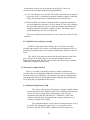
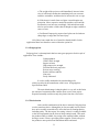
2.4 Motor circuitry Selection
A 6 Volt motor, while being cheap, brings its own issues in regards to control.
Controlling speed and direction, of these motors, is more complicated then plugging
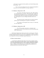
a few wires in and hoping for the best. After investigation, the best way to control a
motor, in relation to speed and direction, is by incorporating a H-Bridge into the
design. A H-bridge works by using electronic switches that let current flow in a
particular direction across the motor. Refer Figure 3.
21
Figure 3. H Bridge simulation -Turning one direction
By changing the switching the motor will turn the other way. Figure 4.
Figure 4. H Bridge simulation -Changed direction
The other beauty of this format is that it can be incorporated with the
PWM output from a Microcontroller to control the actual motor speed.
PWM or Pulse Width Modulation is the process where the power is
switched on and off at a particularly high-speed rate. The on off rate is usually
measured in microseconds so the motor is only receiving power a percentage of
each second. This gradually adds up to a percentage of time on in a minute so
the speed is adjusted accordingly. Interestingly the on and off rate is at such a
speed that measurement with a multimeter would show a constant voltage
supplied and measurement requires an oscilloscope.
Figure 5. Simulated PWM Output
There are a couple of ways to incorporate a H-Bridge into the design.
22
2.4.1 H-Bridge
A H-bridge can be constructed using Transistors and a handful of
discrete componentry Figure6.
Figure 6. Transistor H-Bridge Circuit (The Complete BJT Circuit, 2006)
There are several configurations of these depending on the style of
Transistor used. These have there own consideration so will be addressed
separately.
2.4.1.1 Standard transistors H-Bridge
A suitable H-bridge can be easily built from standard Transistors
like the PNP BC557 General Purpose Transistor (Phillips, 2006) (Data
Sheet available on CD). These are quite capable of handling the power
but suffer with large current drains that can be detrimental to a selfcontained unit operated from a battery.
2.4.1.2 Mosfet Transistor H-Bridge
A Bridge constructed on Mosfet Transistors overcomes the issues
of power because the Mosfet is substantially better on the current drain
issue. The main problem with Mosfets is the price.
2.4.1.3 H bridge Dedicated IC
There are quite a few H-Bridge dedicated IC’s available in
Australia. The main consideration in the selection of a H-Bridge was
price verses suitability for the process. The majority of the H-Bridge IC
solutions were quite expensive, and quite a bit more powerful then would
be required here. These where immediately removed as competitors.
From the rest the L293D (STMicroelectronics, 2006)(Data Sheet
available on CD) from STMicroelectronics was a standout in both price
23
and features. It was capable of driving the two motors that were
required and the circuitry was incredibly simple to initiate into the
design. This unit is also compatible with microcontrollers.
Though some very interesting Transistor H-Bridge designs were found,
the IC version of the H-Bridge was the automatic choice because of the ease of
implementation and the price.
2.5 Microcontroller Selection
There are quite a few varieties of microcontroller available. The selection
approach was a little slanted, because of previous experience and success with the
PICAXE range of microcontrollers, based on the MICROCHIP range. Research on
the Internet and at the USQ Library also verified the popularity, ease of use and
prolific information sources for this range of microcontroller. On the MICROCHIP
website (www.microchip.com) there is also a plethora of addition information on
how to use built functions and examples of operation for its entire range of
Microcontrollers
The final choice came down to two microcontrollers from this Range
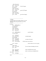
2.5.1 PIC16f628A
The PIC16f628 is an 18-pin microcontroller that offers two banks of 8
pins, called PORTS that are accessible for input and output to peripheral
electronics. The chip also offers the following built in functions as standard:
4 Analog input pins
RX USART Asynchronous Receive capability
TX USART Asynchronous Transmit capability
A Synchronous Data Input pin
A Synchronous Clock
A Capture In/Compare Out/PWM Out pin
An Oscillator In/External Clock In Pin
An Oscillator Out/Clock Out Pin
A MCLR - Master Clear pin
A Timer0 clock input
A Timer1 oscillator output
A Timer1 oscillator input
A Serial programming data Pin
A Serial programming clock Pin
A Low voltage programming input
A External interrupt Pin
This CPU uses a RISC format for its instructions and in this case a small
set of 35 instructions for programming. The speed of the microcontroller can
also be accurately controlled by using an external crystal. This means timing for
specific peripheral interfaces can be timed to precision. It has a 2k Flash
Program Memory, 224 byte Ram data Memory and 128 byte EEPROM Data
memory.
24
This chip also has the option of LVP (Low Voltage Programming) where
the chip can be easily programmed with the relevant code via 5Volts. This is
particularly useful when combined with the ICSP (In Circuit Serial
Programming). In this mode the chip can be programmed in circuit, via the serial
port of a computer with inclusion of a small amount of electronics. This removes
the problem of having to programme, remove then insert in its final circuit and
the related issues of Static Discharge Damage and/or bent pins.
Finally, this processor has a low Power consumption rate and can be
operated on 5 Volts, which lends itself nicely to this sort of application. All of
the data above referenced from (Microchip 2006A).
2.5.2 PIC16F877A
The full MICROCHIP range are very compatible, with one another, over
the full range. They have similar features and similar Programming commands.
This means that the PIC16F877A has all the same features as the PIC16F628A
with the following additions.
4 Banks (PORTS) of 8 Pins for input and/or output
1 Bank (PORT) of 3 Pins for input and/or output
7 Analog/Digital input port
Outputs for both SPI and I2C modes
An SPI Data Out pin
An SPI Data In pin
A Data I/O pin
2 Capture In/Compare Out/PWM Out pins
Slave select for the synchronous serial port
Read control for the parallel slave port
Write control for the parallel slave port
Select control for the parallel slave
Parallel slave port
The chip also has much a much larger Flash Program Memory, RAM
and EEPROM Data memory. The data above and the functionality included on
this Microcontroller (Microchip 2006a). The full datasheet is also available on
the CD
The Pic16f877A is available in a 40-pin configuration. This, with the
added functionality and memory size made this chip the ultimate choice for the
functionality that was intended to be included in the final product.
25
2.6 LCD Selection
At the time of research there were only 2 LCD displays available at a
reasonable pricing. Both were clones of the Hitachi LCD Controller range.
Several other models have appeared on the market since then and will not be
reviewed in the text.
The first includes the following functions:
Control, Refresh and Display functions executed by a dedicated
on-board controller.
Dot Matrix 16 Character x 2 Lines Module
Full 160 characters JIS font set.
Low Power Consumption - 5V Power Supply
5 x 7 Dot Matrix with Cursor
The controller also allows the creation of the new characters. It is
also programmable by either 4 or 8 bit mode. The 4-bit mode allows the
LCD to be enabled with as few as 6 inputs from the microcontroller. This
information and more is available at http://www.dse.com.au/cgibin/dse.storefront/458b31df03fe8ca4273fc0a87f9c0754/Product/View/Z
4172.
They are relatively easy to use though special steps and timing
are required for interaction. An excellent source of information for this
LCD is at http://www.myke.com/lcd.htm.
The second LCD display incorporates the above features with the
added functionality of being backlit. Unfortunately this addition adds an
extra $10 to the price so the luxury was not considered important
enough.
The Cheaper version was therefore chosen.
2.7 Wireless Transmitting and Receiving
There are two cheap alternatives for wireless communication between the robot
and the computer base. The first is the IR (Infrared) communication which entails a
light emitting array and a receiver based in the Infra red spectrum. The second is the
UHF based transmitter/Receiver set in the 434Hz range of this band.
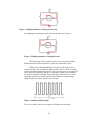
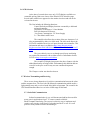
2.7.1 Infra Red Communication
Infrared communication is very well documented and has been used for
many years in applications from T.V. remote controls to Mobile
Phone/Computer interfacing. The system is relatively easy to implement and
requires extra circuitry in the form of a decoder/encoder IC to use. It is well
proven in many instances but has disadvantages
26
(a)
Because it uses light, the units communicating need to be fairly
straight on to one another. There is an angle of Transmission (Figure 7)
that allows communication, but the Transmitter and Receiver must be
facing each other to communicate. If the Robot turned away from the
Transmitter no communication would happen
Figure 7. IR Transmission Angle
(b)
Infrared used outdoors or in high light conditions can be prone to
false signals. As Sunlight contains the Infrared spectrum also this could
theoretically cause difficulty when the computer and Robot were
legitimately trying to communicate.
(c)
Range is also an issue with Infrared with normal ranges in low
light situations being on several metres and IrDa Devices usually having
ranges up to 1m. More information can be found at http://www.irda.org/
the home page of the Infrared Data Association Web Page.
2.7.2 434 Hz UHF Wireless Communication
This method uses the 434 Hz UHF frequency, which has been set aside
for this style of communication device. In difference to the Infrared system, the
434 Hz wireless UHF transmits in all direction at once so the robot does not
need to be facing the unit. The system can also have a range of up to 1km with
the right power source. The modules for this are incredibly easy to use in an
electronic circuit.
The disadvantages of this system are:
(a) Just as the multidirectional properties of 434Hz wireless are a bonus
they also become an issue when multiple units are operated in the
one area. Where an Infrared unit could be aimed at a particular robot,
all robots receive the signal from the 434Hz UHF system. This would
require workarounds in the software.
(b)
The full effect of radio waves and the human body is still a grey
area of science and medicine. Prolonged exposure to these waves
could cause a health hazard. The time of exposure in reality should
be seconds in an hours use but this is still a small issue.
27
Both methods use similar electronics to interface and the cost of implementing
both are relatively even. In the end it came down to the fact that the sender
would most likely be plugged in at the back of a computer and possibly not be
able to be used in plain sight of the receiver.
The TX434A and the RX434 sender and receiver from Oatley
Electronics www.OatleyElectronics.com were chosen for the application
because of price and availability. More information on these two components on
the CD).
2.8 RS232 discussion.
The RS232 output from a serial port is based on an old system where
logic 1 is at +10 volts and the logic 0 is set at –10 volts. This system has its own
standard, which sets the pins of the cable and Computer port. A good source for
information on this is
http://www.camiresearch.com/Data_Com_Basics/RS232_standard.htm.
Unfortunately the voltage for a Logic 1 is +5 volts and Logic 0 is Zero
Volts in a microcontroller. The microcontroller is also unable to produce voltage
at the correct voltages to interface directly with a computer. The addition of a
wireless connection between the computer and Robot also amplifies this
problem, as the wireless connection has similar limitations.
One way around this is to incorporate a RS232 Transmitter/Receiver IC
into the Transmission side of the circuit near the Computer. An ideal IC for this
is the Maxim RS232 (Texas Instruments, 2006)(Data Sheet available on CD).
The Max232 coupled to the output of the Computer turns the voltages into a
logic level acceptable by the Microcontroller and wireless system. The Maxim
IC also has a built in Voltage Pump so it can convert the Microcontroller output
to the correct voltages to interface the microcontroller signal to the computer, if
required.
28
Chapter 3. Chassis Material Selection and Design
As the robot would be used by children, in a classroom situation, and would
most likely be mistreated, the chassis of the robot required particular consideration. The
following designs and materials were considered and/or tested:
3.1 Chassis Type Selection
One Constraint on the design of the project was the ability to turn in its
own axis. There are 2 ways to effectively do this either using tracks like a tank or
by creating a three-wheeled design.
Motion by tracks is a common mode of locomotion in the modern world.
Many vehicles use this method of motion and it is extremely successful and
stable. Tracks would be a simple method of implementing motion in this situation
as well as steering. Tamiya offers a kit in their educational Construction series
that would work for this situation while supplying the chassis for the robot in one
piece.
A three-wheeled robot, in comparison, could be made, quite simply, by
inverting a Servo on some sort of chassis and building a mount for the wheel.
Because the PIC16F877A has the ability to offer PWM to a servo this method
would be easy to incorporate into the design
The Track method would have easily provided the chassis and a simple
method of motion and steering. For this project though, the 3-wheel robot method
was chosen for 3 reasons.
1) The Tamiya Track model is built from moulded plastic and
hence may not stand up to the anticipated abuse during use.
2)
The interesting construction, design and programming
aspect of the build three-wheeled.
3) The difficulties in designing a substantial Track system as
apposed to the three-wheeled system.
3.2 Chassis Material Selection
Once the chassis design was decided upon a suitable material was
required to build it from. The following materials were considered.
3.2.1 CD Ply.
CD ply is a common building material readily available at hardware
shops and timber stores. It is relatively cheap, lightweight and
reasonably easy to work. Its main downfalls are:
29
a. It is timber and as such can have very raw edges or splinters. This
can be a danger for children or people handling the robot. There also
could be a danger of injury, from splinters, if the robot brushed past
someone, while moving across the floor.
b. If the robot was flexed excessively, as in the case of someone
stepping on it, though plywood is relatively flexible it may splinter
and injure someone.
c. CD ply is often only available in full sheet size. This would make it
rather expensive to make single units.
d. Ply is not very strong in its end grain so screwing or fastening that
involved fixing into the end grain would be less then satisfactory.
For these reasons plywood was rejected as a chassis material.
3.2.2 Maranti pine.
This wood is very readily available at any hardware shop or timber sales.
It is very strong and is quite reasonably priced.
Its main downfalls are:
a) It is timber and as such can have raw edges or splinters. This
can be a danger for children or people handling the robot. There
also could be a danger of injury, from splinters, if the robot
brushed past someone, while moving across the floor.
b) Pieces of Pine 150 mm wide as required for this project are
prone to cupping which would make the robot inoperable
overtime unless the timber is treated. Treating could be achieved
by painting, another process and another cost for the project.
Pine was therefore removed as an option.
3.2.3 Metal.
One of the strongest chassis materials available would be metal. It is
very readily available and could be formed as a flat plate or folded sheet.
While this would be the strongest option it offers its own unique
disadvantages:
a) Metal is a highly conductive material. This means that all
electric and electronics would need to be specifically insulated.
This of course would increased the time and cost involved in
building.
b) Special tools and skills are required to machine or fold solid
and sheet metal. Machining of metal is also labour-intensive and
costly. It also requires specialty tools to do successfully so
construction would need to outsource this part of construction.
30
c) The weight of the project would immediately increase in the
case of solid metal construction translating into cost as motors
and drive assemblies would need to be increased in size to cope.
d) If the chassis is made from steel plate it would require rust
protection. More expensive metals like stainless steel could be
used but the costs increase accordingly. Galvanized iron could
also be used to make a folder chassis though cut edges could be a
source of rust.
e) Cut Hazard. Improperly prepared steel plate can also harbour
sharp edges or snags that can cause injury.
All of these issues made the use of metal less then desirable for this
application. Metal was therefore removed from the option list.
3.2.4 Polypropylene
Polypropylene is a thermoplastic that has some great properties for this style of
application. These include:
Lightweightness
Good Tensile strength
Impact resistant
High compressive strength
Excellent dielectric properties
Resists stress cracking
Retains stiffness and flex
Non-toxic
Easily fabricated
It is also readily machined with woodworking tools,
which is perfect for the manufacture of this item. (Polypropylene
Specifications 2006)
The main disadvantage is that the plastic is very soft so this limits
the amount of construction that could be done as an in class project.
Repeated assembly would soon strip the plastic from the screw holes.
3.2.5 Final selection
After careful consideration of the above materials, Polypropylene
was the stand out choice. Although the in class assembly activity would
have to be carefully reconsidered, it offers the best all round properties
including safety. The best aspect, for testing, is that it is readily available
at the local supermarket in the form of cheap cutting boards. This made
the product readily available, for testing or the amateur builder, without
having to source it from a specialist plastics supplier. Plastic also gives
the product a more professional finish then timber and metal.
31
3.3 Chassis Design
There was an idea, in the early stages of the project, to include basic assembly,
into the design, as an option for the children. This would give a teacher the
opportunity to incorporate this as a class activity. Assembly would also give the
children a feel for the important hands on aspect that is so relevant to modern
engineering.
3.3.1 What is Assembly?
The choice of Polypropylene as the chassis material bought forward
the above question. If the robot was to be in several parts, and these parts
needed to be to be reassembled, how would this happen?
The most obvious method of assembly would involve screws.
Screws are readily available, easy to use and have a proven ability as a
fastener. Screws, though, instantly cause several issues:
(a)
Polypropylene, while having some very good properties, is a
plastic and as such has issues with threading when it is
screwed into.
(b)
Children of the target age have limited dexterity and as such
controlling a screwdriver and negotiating screws into specific
holes may be an issue.
(c)
Screwdrivers are sharp and pose a stabbing hazard. The best
of us have stabbed ourselves with a screwdriver so children
unaccustomed to handling this type of tool would be very
likely to injure themselves and/or others.
Obviously if assembly is to be involved, some adjustments
parameters to the term “assembly” were required.
More thought, with respect to the above issues, showed the robot
main chassis, drive train and related parts needed to be supplied in an
assembled format. This would mean the parts that required assembly by
screwing would need to remain attached permanently.
This revelation then left only one aspect of the robot that could be
assembled onto the robot – the electronic component board assemblies.
Possibly a way could be found to attached these so the construction
aspect of the robot was still available.
Screwing and gluing were automatically removed from the list.
The implications of screwing were discussed earlier and carry the same
issues in this instance. Gluing is usually final so this was not a
consideration.
After a lot of thought, on the issue, it became obvious that circuit
boards all have a couple of common features, Thickness and Rigidity.
32
These meant if slots were cut into the robot the board assemblies
could be easily pushed into these. From there the cords would be plugged
into the relevant socket on the mainboard and the construction content of
the project would be achieved.
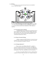
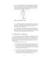
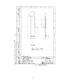
3.3.2 Printed Circuit Board Mounting
A slotted upright was then designed to handle the PCBoards.
Experimentation showed that a 1mm thick slot 5mm deep adequately
help the boards in place while letting a child push the board assemblies
into it. The riser design took into consideration that the main board
would lie in front of it, though; provision for it to be in another spot was
available.
The upright also needed to be robust enough to handle abuse.
There was no real need for stress testing, because of the minimal stresses
and the properties of Polypropylene, so a 40 mm section was decided on
as it looked substantial enough to do the job
The riser board Appendix E Sheet 4 Item 6 was the result. This
board allowed assembly without any sort of fasteners. It is worth
mentioning that only 2 circuit board assemblies now require fastening on
this project. They are the two boards holding the Hall Effect Sensors.
These need the stability and adjustment that a screw and slotted board
offers. The remaining boards are attached to the unit by locating slots.
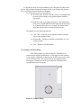
Two side braces were also designed Appendix E Item 5 Sheet 3
to give added sideways stability in the event the robot was dropped on its
side or it was tripped over. Figure 8 shows these in place.
Figure 8. Riser with slots
33
3.3.3 The Chassis and Drive Assembly.
The chassis layout and structure now required some constraints and
rationalisation.
The power supply was finalised and would be salvaged from the cheap
spotlights available for $10 to $20. These carry a Sealed Lead Acid Battery
(SLAB), charging circuit and power supply to run the charging. Purchased
separately these would be a substantial cost to the project. The SLAB batteries are
6V and have a 4.5AH capacity, which, is more then enough for the little bit of
current drawn by the electronics and the motors.
The battery would then be the heaviest part of the project. The best place
to carry this would be over the rear drive wheels, to let the steering work easily
and to stop tipping. These batteries have a footprint of around 70 mm x 50mm.
The upright would need to be allowed for.
A servo for steering would also be required.
Allowing for the above parts and a little extra 220mm long was chosen
as the working length for the chassis. .
The drive train was the next consideration. Gearing, motors, shafts and
wheels were required. The Tamiya Avante 2001 Snap together racer kit from
Dick Smith electronics, at $9.95, was chosen to supply one motor, the drive
shafts, cogs and wheels required for the drive. This kit is a 4-wheel drive so it has
2 drive shafts that supply all the necessary parts for the dual motors of the robot.
Laying the two motors and the two drive shafts and wheels out set the
width at 150mm. The final design of the chassis board is shown in Appendix E
Drawing 5.
3.3.4 Drive mounting
The motor and shaft assemblies required proper mounting so the robot
could move and the whole assembly remain stable. This assembly also needed to
be robust enough to handle repeated use and interaction with children.
This posed the question what to build the assembly from? Metal would
be the ultimately choice but as discussed earlier there are issues with manufacture
and weight especially for a homebuilder. With a little thought Polypropylene
because the obvious choice for all the reasons discussed earlier for the chassis.
The use of gearing and shafts meant the motor and wheel assemblies
would be mounted separately.
Considerations for motor shaft mounting:
(a) The mountings would be as compact as possible
34
(b) The mountings for the shaft should incorporate mountings
for the motor as well.
(c) The parts should be easy to construct
With this in mind the parts were laid out in and the mountings were
designed by trial and error.
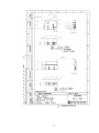
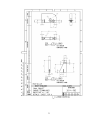
Technical drawings of the Drive Mountings can be viewed in Appendix
E. The mountings were designed from the centre out. The central mountings
were designed using the circular end on the motor for mounting and the length
of the main shaft. Item 4 on sheet 3 was the final designed to hold these.
The other end of the motor now needed to be mounted. With a small
pinion gear directly mounted on the motor an intermediate cog also required
mounting. As a result Item 2 on Sheet 1 was designed. The drawing shows how
the flat motor shape was used to hold the motor in the mounting.
The Wheel Mount Item 2 of Sheet 2 was designed to hold the other end
of the intermediate cog and the wheel end of the main shaft with space for its
cog.
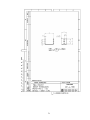
The full assembly can be seen in Appendix E – Drawing 7 and in
FIGURE 9.
Figure 9. Drive Assembly
Aluminium rivets were used as bushes for the drive, (with the pull
removed) and the intermediate cog shafts (with the pull in and trimmed). There use was
to stop any wear in the plastic that spinning shafts may cause.
3.3.5 Steering
As was indicated above the Robot was to be three- wheeled. In this
configuration the Servo would be mounted, inverted, in a hole cut in the chassis
35
(Appendix E Sheet 5 Item 7). The wheel is then mounted onto the Servo Horn via a
bracket (Appendix E Sheet 6 Item 8). This allowed an easy wheel configuration
that was easy to interface with the Electronics.
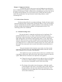
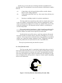
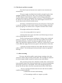
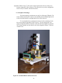
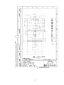
3.3.6 Peripheral Mountings.
The final mounting consideration was the Line following PCBoards. The
nature of this board meant it requires some shielding from incidental light and it
needs to hold the board low enough that the line can be detected.
To accommodate this a redesigned version of one the mountings for the
drive was produced (Appendix E Sheet 2 Item 3). The new design has a slot
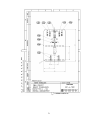
along its length that allows the board to slide into and be held while in operation.
This is then attached onto the chassis at the front (Appendix E Sheet 7) and can
remain in situ.
Figure 10. Assembled Robot with boards in situ
36
Chapter 4. Electronics Design
4.1 Test Bed/Robot Main Board
Once the method of programming and computer interfacing were
finalised the next step was to build a testing bed. Originally this was done with a
dedicated board using PicPGM
(http://www.members.aon.at/electronics/pic/picpgm) and the Low Voltage InSystem Programmer circuitry (LVISP)(Appendix C) interfacing with the
PIC16f877A on a breadboard. The programming, powering down, removal and
reinsertion became time consuming and quite monotonous. As a result the first
major board designed to be the test bed was instigated.
The first item, in the design, was to implement the LVISP so the chip
could be programmed and then quickly run to test the code. If there was an issue
the PIC needed to be able to be quickly reprogrammed again. To get around this
Header Terminal Strip and Jumper Shunts were incorporated in the design to
facilitate the change.
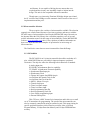
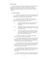
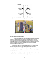
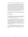
A careful look at the PIC16F877A Pin out Diagram (FIGURE 10.) will
show that, while the microcontroller offers a good variety of functions, its layout
is a little jumbled. This meant designing to bring relevant areas together and
have all of the same PORT pins accessible from the same point. Doing so
allowed for a cheap, user-friendly header plug system to be used to stop the
possibility of cables being plugged in backwards. While there was little chance
of damage to the electronics, it creates a debugging issue that might not be easily
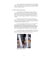
rectified by an inexperienced user.
Another addition was a reset button so the Microcontroller could be reset
in case of error or just to restart a sequence of code. The reset button could be
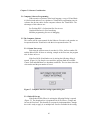
easily left out of production assembly without detriment to the circuit.
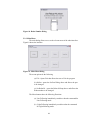
The power supply circuitry was chosen because it was envisioned that
the main board would also supply power to other parts of the robot. Early trials
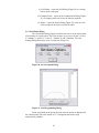
of this showed the microcontroller was prone to reset especially when a high
draw item like a motor was changing direction. This was rectified by
incorporating a couple of large 470uF capacitors across the feed and supply pins
of the LM7805 to smooth the power at the demand time.
Schematics are provides in Appendix E for this main board and a picture
of the mainboard can be seen with Figure 11.
37
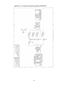
Figure 11. Pic16F87XA Pin out Diagram (Microchip, 2006b)
Figure 12. Picture of Mainboard
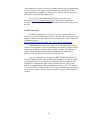
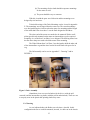
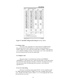
4.2 Line and light following Circuitry
Light Dependant Resistors (LDR) (Data Sheet available on CD) are used
to detect the line or light differences required to follow these sources. Red 5mm
LED’s were used in conjunction with the LDRs to reduce the effects of incidental
light on the sensing. The use of LEDs should also reduce the effect of a darker room
where the LDRs will move towards infinite Resistance and move outside the
parameters of the Microcontroller ADC.
Even though the LDRs were purchased at the same time from the same outlet
there was significant differences in the output resistance at the same light. To
counteract this, the 10K resistor suggested for the theoretical circuit were adjusted as
necessary to bring resistances within a reasonably close range.
In this configuration the LDR’s output is sufficient to interface with the ADC of
the PIC16f877A without further electronics.
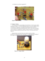
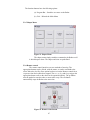
The addition of a terminal strips and Jumper shunt allows the Leeds to be turned
off if the board is used in Light following Mode (Figure 12)
38
A Schematic is provided in Appendix D.
Figure 13. LDR Circuitry
4.3 Compass Circuitry
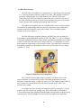
Two issues need to be acknowledged with the Dinsmore 1490 Compass module
discussed in Chapter 2.3. The first being that the pins are very closes together and are
a little flimsy in construction. According to the specification sheet crossed or
reversed current can destroy the internal circuitry. Likewise, time in the solder pool
is also a concern. To combat this a 16 pin IC socket was cut into 4 x 3 pin sockets to
insert the component and help remove the above issues. The result can be seen in
Figure 13.
Pull-up resistors were then all that was needed to interface with the
PIC16F877A. The pull-up resistors create logic 1 or 0 depending on the bearing of
the compass. This logic level can be read directly by the PIC16F877A.
Figure 14. Compass Board
39
4.4 Hall effects circuitry
The Hall Effects assemblies were constructed in as 3-part design. The first being
2 x 33 pin cogs attached to the drive shafts of the robot. This supplied a method of
accurately reading distance in a 13mm diameter piece. Because of the room
constraint a single UGN3503 Hall effect sensor board was created for each side of
the robot. This board consists of only the sensor and points for power in and sensor
output. The board also enabled easy mounting under the robot.
The addition of a magnet to the rear of the Hall effect sensor was then required.
The South of the magnet being attached to the sensor meant the sensor would detect
when the teeth of the magnetic cog are in the vicinity. These assemblies and the
magnets can be seen in Figure 9.
The Hall effect processing board features an LM833 low noise OpAmp (ON
Semiconductor, 2006)(Data Sheet available on CD). The LM833 is set up in a Window
Comparator configuration using a voltage divider with 200Ω potentiometer and a 100Ω
resistor for each side of the robot as the voltage reference. “A 'comparator' is a circuit
that compares an input voltage with a reference voltage. The output of the comparator
then indicates whether the input signal is either above or below the reference voltage.”
(VanRoon, T. 2006)
Figure 15. Hall Effect Processing Board
The UGN3503 has an output voltage of around 1 volt when connect in the
format when there is no metal in its presence. The 200Ω potentiometers are then
adjusted to match this voltage so logic 0 (0 volts) is sent. The output from the LM833 is
then a square wave moving between 0 volts and 5 volts that the Pic 16F877 can
interpret as movement.
To complete the drive assembly and incorporate position sensing two 33 tooth
metallic cogs were chosen from a hobby shop. These allowed the measurement of
1.515mm increments when calculated from the 98mm wheel diameter of the previously
selected wheels. This was thought to be quite accurate enough for this application.
40
4.5 H Bridge Circuitry
The H bridge circuitry is quite unremarkable because the L293D takes all of the
complication out of the circuitry. All that is required besides the power and earth is
the PWM signal from the Microcontroller for each side and logic high of 5 Volts to
enable each side of the H-bridge controller. In this instance they are connected
together at the PIC16F8767A because when the Motors are to be shut off both
motors will be disabled at once. As mentioned before the PWM is supplied from
pins RC1 and RC2, the CCP2 and CCP1 outputs. This is sufficient to supply the
power to actuate the L293D. The output is simply 2 power lines that connect straight
to the motor.
4.6 434 Hz Transmitter and Receiver
The Receiver module is a straightforward connection only requiring power,
an earth and the data out line. A long track on the board was created to act as the
antenna to save having an external antenna.
The Transmitter module is a little more involved with the inclusion of a
MAX232 IC (Texas Instruments, 2006) (Data Sheet available on CD)
incorporated into the design. This IC converts the RS232 output from the Serial
Port to Logic levels for the PIC16F877A as discussed in chapter 2.8.
The connection to the MAX232 is a little back the front from the expected.
The inputs and outputs are in relation to the IC itself so to transmit a signal from
the computer the signal goes into the Received pin 13 (R1 In) and is sent out via
Receiver pin 12 (R1 out).
The R1 output then goes to the Data pin on the TX434A (Pin out available
on CD). An extended track on this board also acts as an antenna to save having
an external antenna. The only other connections required are the power and the
earth.
4.7 LCD Module.
The LCD PCBoard is also quite unremarkable and only used to mount the LCD
module, a potentiometer and the header to interface to the PIC16F877A. The
potentiometer is used to adjust the contrast on the LCD. The potentiometer ties the
voltage, the ground and the contrast pins together. Adjusting the potentiometer
adjusts the contrast accordingly.
Figure 16. Hitachi 44780 LCD Pin out (Hitachi, 2006)
41
The LCD has been set up in the 4 Bit configuration so only 6 pins are needed to
run the LCD and send the required characters to it. The Read/Write pin is tied to the
VCC Line so it is easy to write all of the time. Lines to the Register Select, Eclock,
D14, D13,D12 and D11 are all that is necessary then to interface the LCD module
and the PIC16F977A together.
4.8 Stop Button Circuit
The Stop button circuit is simply a mount so the button can be pushed if the unit
is in eminent danger or needs to be instantly stopped.
4.9 Connecting it together
The schematics in Appendix D show the connections of each electronic module
to the Mainboard housing the PIC16F877A. Board groups are connected together
with an 8 pin Header so the group plugs into a specific Port and relevant pins are
correctly aligned. Inserting the wrong board plug will just result in inappropriate
behaviour in the robot.
Power is has been deliberately kept separate so there is no chance of catastrophic
failure due to power being introduced into the wrong area. This system will not, of
course, stop a concerted attempt to put power into an incorrect spot. It will make it
easy for someone who is trying to assemble the system, with limited knowledge,
doing accidental damage.
As discussed earlier similar areas are grouped together where possible. The
PortA group has the ADC dependant inputs of the Light/ Line following sensors and
the compass inputs on it. This is a grouping of directional sensors
The PortB group has the inputs from the LDR and the Emergency button. Both
of these peripherals fire interrupts on the Pic16F877A when actuated so are necessarily
on PortB, which has this option available.
The PortC group houses the Servo control, H-Bridge, its Enable control, the Motor
Directional control and the Received data from the computer interface. The
PIC16f877A PortC carries motor functions in the form of PWM generation and the
Receive/transmit UART area. Grouping the Motor Direction and the Servo control in
the same area utilises this Port to its fullest
The PORTD area houses the controlling of the LCD interface and the Music
output board.
42
Chapter 5. Software Consideration
5.1 Computer Software Programming
With extensive experience in the basic language, a copy of Visual Basic
6.0 Professional and access to a plethora of Visual Basic programming sites for
reference the obvious choice for the computer software was Visual Basic. The
advantages of this software are:
Pre-Existing DLL’s for functions like Port Access
Graphical interface for User Interfacing
Modular programming for ease of debugging
5.2 The Computer Software
This section will be a user manual for the Software. Extensive code remarks are
incorporated into the Visual basic code that is incorporated on the CD.
5.2.1 Comm. Port set-up
Each time the software starts it searches for 2 files, the Port number file
and the Robot Id file. If these are missing, example at the first start, the program
asks for these to be set.
If the Port Id file (PortNumber.txt) is missing the following dialog is
opened (Figure 16). By simple error control the program finds the available
Comm. Ports and adds them to a dropdown combo box. The user then selects the
relevant box and the port number is saved.
Figure 17. Computer interface setting request dialog box
5.2.1 Robot ID Set-up
If the Robot ID file (ID.txt) is missing the following Dialog is opened
(Figure 17). The dropdown box is populated with 26 ID Letters. A single unit
can use the first letter. This function is not properly implemented here, though
the code is ready to apply it, as multiple bots were not available for the testing
43
Figure 18. Robot Number Dialog
5.2.2 Main Menu
The main dialog allows access to the relevant areas of the robot interface.
Figure18 shows the interface
Figure 19. Main Menu Dialog
The menu options do the following
(a) File - Opens Exit that allows the user to Exit the program
(b) SetPort - opens the Set Port Dialog above and allows the port
to be changed
(c) Set Robot Id – opens the Robot Id Setup above and allows the
Robot number to be changed.
The Menu buttons have the following Functions
(a) Line Following immediately sends the robot the command for
Line Following mode.
(b) Light Following immediately sends the robot the command
for Light following mode.
44
(c) Grid Points – opens the Grid Dialog (Figure 20) so a design
can be made on the grid.
(d) Compass Points – opens up the Compass Point Dialog (Figure
21) so compass points can set for the robot to negotiate.
(e) Shapes – opens the shapes dialog (Figure 22) so the user can
select a shape for the user to send to the robot.
5.2.3 Grid Points Dialog
The Grid Points Dialog (Figure 20) allows the user to set the robot a path
of movement via a grid system. The Grid can have its axes set to X and Y- Letter,
X –Number Y -Letter, X – Letter Y – Number, X and Y Numbers. The Axis
Setting Dialog allows these to be set each time (Figure 19).
Figure 20. Set Axis Option Dialog
Figure 21. Grid Programming Dialog
Points are plotted on the grid at the same time the points are displayed in
the column on the left so the format of X, Y navigation that can be easily
understood by children.
45
To operate the cursor is moved around the grid. A Dragline will show where
the line will go. Right clicking will remove the line. Left clicking will place the
line as a solid line and activate the next Dragline.
Two things that need to be remembered:
(a) The robot starts from the 0,0 point, whatever combination this
becomes by the settings, as any grid navigation would be
expected to.
(b) Each increment on the graph represents 10cm (100mm) this
needs to be remembered because the robot will hit any objects
in or falloff surfaces that are in its path. This format of the
robot does not have these external collision sensors.
The buttons have the following functions
(a) Clear Grid – Clears the grid and all the variables related to
any previous grid movement.
(b) Program Bot – Sends the coordinates to the Robot so it can
start to navigate.
(c) Exit – Returns to the Main Menu.
5.2.4 Compass Interface Dialog
This Dialog (Figure 21) allows Compass Coordinates to be
entered via the compass point buttons. A Line appears on the compass
screen and the coordinates are displayed in the left list box so the results
can be viewed as both a line direction and as the compass bearing.
Pressing the C Button cancels the previous points. The lines can be
cancelled back to the first point.
Figure 22. Compass Dialog
46
The function buttons have the following options:
(a) Program Bot – Sends the set course to the Robot.
(b) Exit – Reloads the Main Menu
5.2.5 Shapes Menu
Figure 23. Shapes Menu
The shapes menu simply sends the command to the Robot to tell
it which shape to draw. The shapes and sizes are predefined.
5.2.6 Remote control
The remote control interface uses two methods of steering. The
appropriate buttons can be clicked, with the mouse, to send a command to the
robot. Otherwise, the Key Press option has been set on the Remote control form,
so presses from the keyboard are trapped. The w, z, a, d, g and s keys trigger the
appropriate button event so the robot can be operated remotely. The go button
must be pushed to start the robot or restart after a stop. The exit button
automatically stops the Robot at the same time.
Figure 24. Remote control menu
47
5.3 Interesting Aspects of the Computer code.
5.3.1 The Communication Port code.
Visual basic 6 has built in OCXs and DLLs that handle most of
this interfacing. These works fine on all Windows O.Ss Pre XP or the NT
series. For the later versions a port interface like Inpout32.dll
(http://www.logix4u.net/inpout32.htm) is required. Logic4U, the coder
of this interface software, was approached and rights were given to
include this DLL with this software in any future incarnation.
As for the Visual Basic code (Appendix F.3.) , the relevant
comport is called, it is turned on and the data is sent. This interaction is
very easy.
5.3.2 The Grid Code.
Many aspects of this code were taken from Multilin.zip by Ethan
at www.freevbcode.com/ShowCode.asp/?ID=1240. The original code
was horribly fragmented and hard to follow. The code has been reworked
and optimised.
The code (Appendix F.1.) initially plots an evenly spaced grid of
dots on a Picturebox control. From there a Dragline is fed out behind the
cursor. This allows a visual indication of where the line will go. The
code also allows for the line to drawn from the nearest Grid Point and the
removal of the Drag Line when the left mouse button is pushed.
A coordinate history has been made available so all past
coordinate additions can be erased.
Because of the difficulty in working trigonometry and angles in
the PIC16F877A, code that works out the angle and movement in
relation to the last was created in Visual Basic. This code breaks each
direction down into an angle of 360 degrees in relation to the last
direction with straight ahead being 0°. The required rotation is broken
down into quadrants and the new heading is placed into its quadrant and
the angle amount is deducted. The angle and the tangent is then worked
out from the remaining angle that is less then 90° The Quadrant amount,
in degrees, is then re-added e.g. 250° will be in the 3rd Quadrant. 250 –
180 is 70 degrees. The 70° angle and the tangent are found by the tangent
rule. The 180° will be then be re-added to give the true angle.
It was discovered that the graph and grid points could only give
2° accuracy. As a result it was possible to halve the angle before sending
it to the robot. This was done to fit within Hexadecimal constraint of Hex
FF or 255 decimal. Dividing the angle in half means the angle can be
sent in one 8-bit burst, and later doubled at the Robot end, because 360
divided by 2 is 180. Figure 24 demonstrates the constraints of how a
single character is sent from the computer to the Robot.
48
Figure 25. RS232 Protocol Form (Kim, 2006)
“The diagram above shows using the common 8N1 format. 8N1
signifies 8 Data bits, No Parity and 1 Stop bit format. The RS-232 line,
when idle, is in the Mark state (Logic 1). A transmission starts with a
start bit, which is Logic 0. Then each bit is sent down the line, one at a
time. The LSB (Least Significant Bit) is sent first. A Stop bit (Logic 1) is
then appended to the signal to make up the end of a transmission. “(Kim.
2006), in layman’s terms The PIC16F877A expects to see a zero to start
then a combination of 8 ones or zeros to make up the data then a one to
say it is finished. The combination of 8 ones and zeros are where the
constraint comes in. Figure 25 demonstrates how the largest binary 8-bit
number is represented and its equivalent binary representation.
Figure 26. Binary Decimal Equivalents
It can be seen that adding all the digital amounts 128 + 64 + 32 +
16 + 8 + 4 + 2+ 1 = 256. This is how numbers and letters are sent via
modems.
In this application using the binary representations of 0 to 180 for
the halved degrees. The value can be sent in one 8 bit data bit
represented as 1’s and 0’s and doesn’t need to reassembled in the
PIC16F877A from two passes as a number like 359 would need. In
reality, the 180 degrees would be represented as 0, but to demonstrate the
decimal number 180 would be represented in binary as 10110100 in its
8-bit form.
5.3.3 The Compass code
The compass code (Appendix F.2.) uses the picture box again to
show the progress of the robot. A representation of a compass is used for
the navigation buttons. As the buttons are pushed (Figure 21) a line is
drawn on the screen and the compass directions are placed in the list box
at the side. The compass directions are converted into a 4-bit code
representing the expected input from the compass on the PIC16F877A.
This is explained more thoroughly in 5.4.2
Incorporated in this code is a direction history so a sequence of
instructions can be deleted back to the initial starting point.
49
5.4 PIC16F877A Coding
The coding format selected, for programming the PIC16F877A, is
ASSEMBLER. Assembler enables a compact code that can even allow code
sections to be timed for important functions. Code written in it can be easily
optimised. It was chosen for this reason.
Assembler is not the “dream” language it may appear to be. Grasping its
concepts is difficult, it is often not very well explained and it has no formatting
in the way of modules or the OOP of higher languages possess. To make the
code more readable the code for this project have been placed in similar section
e.g. Motor codes and codes relating to these go into the same section. This made
debugging the code much simpler.
The microcontroller controls nearly every aspect of the robot from
producing the PWM for the motors and servo to counting the distances moved.
A good amount of commenting is done in the ASM file so an overview of the
more important modules will be shown here. The full coding is available in
Appendix H.
5.4.1 LDR Sensor Code
The LDR coding (Appendix H.1.) involved using the ADC functionality
of PORTA on the PIC16F877A. This function allows the use of the internal
ADC unit of the microcontroller. This basically charges and discharges an
internal capacitor using the resistance found on the Port Pin. The capacitor
discharge is timed then the PIC converts the time into a digital value. Using this
method the LDR with the lowest value (the one with the line under it) can be
found by continually polling the 3 pins. If the LDR to either side is on the line
the robot will turn so the lesser value is in the centre.
5.4.2 Compass Coding
The compass pins are attached to Pins 4,5,6 and 7 of PORTA (Figure
10). These pins are set to digital input because of the output properties of the
Dinsmore Compass. The full port is read and the irrelevant bits are removed.
The port is read every 0.5 seconds.
The output of the compass is a 4-bit word.
N
NE
E
SE
S
SW
W
NW
1000
1100
0100
0110
0010
0011
0001
1001
50
This is made up of the logic 1’s and 0’s that indicate the compass direction.
To find if the robot is heading in the right direction the code checks the
current direction against a look up table with the above binary codes in it and
takes note of the table number of the relevant binary code. The required
direction binary code, sent from the computer, is checked in the same table. Its
Table position is also noted. Depending on the differences between these two
values the robot will turn either left or right e.g. the robot is heading SW (0011)
position 5, keeping in mind the tables first entry is counted as 0, and the new
coordinate is E (0100) position 2. The difference is less then 4 table positions
before the current bearing so the wheel turns right and the robot reverses until
the new position is found. If we were heading SW (0011) and wished to go N
(1000). North is greater then 4 positions before in the table so the wheel turns
left and the robot reverses until the correct heading is reached.
The Hall Effect Sensors are used to detect the distance travelled. This is
updated each step and is discussed in the Interrupt section. The code is shown
in Appendix H.2.
5.4.3 Grid following code.
The code (Appendix H.3.) firstly receives the list of angles and tangents
produced in the Visual Basic code as discussed in 5.3.2. Each piece of data is
stored in the memory area range of A0h to FFh (Figure 26). This allows 95
entries or 47 different directions to be added.
The code then loads the first angle. The angle data is halved to see if the
angle of movement is greater or smaller then 90 (this represents a full 180
degrees). Depending on the result the robot wheel direction is set. The original
angle is then doubled to return it to its true 360° representation. The robot is
reverse on one wheel until the angle is correct. The Hall effect Sensors detect the
movement. By taking the distance at the centre of the two wheels it was
calculated that the sensors would be able to detect approximately 1.5 degrees of
change. The code counts the degrees moved in this method and stops when the
required distance has passed.
The tangent amount is then loaded from memory and the robot moves
forward counting the Pulses from the wheels. The robot is set to move 100mm
for each space on the grid. 66 pulses are equivalent to 100mm. So 66 pulses
from the sensors are counted for each unit until the tangent amount has been
reached.
51
Figure 27. Pic16F877A Register File Map (Microchip, 2006b)
5.4.4 Motor Codes
The motor codes (Appendix H.4) control the built in PWM function.
They use the built in Timer2 function to control CCP1 and CCP2 pins of
PORTC (Figure 10). This section also controls PIN 3 of PORTC. This has been
set to enable the H Bridge circuitry. Forward and reverse is also controlled from
here by raising the logic level on the required pins.
5.4.5 Shapes Codes
The preset shapes are preloaded into the Microchip EEPROM
(APPENDIX G). This memory stays viable when the power is removed from the
microcontroller and is therefore in memory at all times. The shapes movement
code uses most of the Grid following code to operate. Code is shown in
Appendix (H.5)
5.4.6. Servo Interfacing
The Servo interfacing section (Appendix H.6.) acts in conjunction with
the TMR0 inbuilt timing function. TMR0 is set to run a continual 20ms PWM
cycle. Another timed code sequence adds the 13,7 or 18 ms high pulse that selects
the direction the servo turns.
52
5.4.7 Port Interfacing
This area initialises all the timer functions in TMR0 and TMR1 and all of
the Ports on the microcontroller for their required function.
5.4.8 Interrupt section
The Pic16F877A has a special interrupt function, which can be set to
react to various events. These events can be anything from internal specifically
timed interrupts to external inputs from the ADC or other pins on the
microcontroller. Once the event fires the interrupt the code leaves what it is doing
and moves immediately to the code that services required event. Using this
interrupt feature allows the microcontroller to interface with the outside world.
As such the interrupts are the heart of the coding. Important codes like
the emergency push button stop are coded here. The interrupt section also houses
the Hall effect sensing response so positioning takes priority. The timer functions
and the music start here.
Most importantly the wireless interfacing is done here so the message is
received on the wireless port, as it is ready. Code detailed in Appendix H.7.
5.4.9 Sound Section
There are several ways to implement sound on a Pic16F877A. Many
involve converting Midi files or similar into electronically identifiable data.
Research into implementing music showed that the Pic16f877A is capable of
interacting with peripheral electronics to produce quality music. Most of these
methods are quite involved and appeared to be outside the scope of this project.
An easier way to do this was required. It was noted, during this research, that it is
possible to produce a beep in a piezo speaker with minimal peripheral electronics.
Bringing music back to basics, one must realise that providing a vibration
at a particular frequency produces a particular musical note. In different musical
instruments this is done in various ways. A stringed instrument vibrates its strings
at the particular frequency to form a note or a chord, where as a wind instrument
might vibrate a reed to produce the required sound waves. Likewise a stereo sends
a particular vibration to a speaker to produce each note.
With this in mind research focused on discovering the frequencies for
individual musical notes. The theory being if the individual note vibrations could
be produced from the Pic16f877A, music could be played by inputting the notes
from sheet music.
The internet site http://www.phy.mtu.edu/~suits/notefreqs.html deals
with the physics behind musical note frequencies discussing the frequencies in Hz
and the wave lengths in cm’s. Considering the plethora of information on hand at
the site, and trying to put it into perspective for this project, the first idea was not
53
to try producing symphony quality music. With this in mind all notes except the
Major scale could be ignored. This would leave the basic notes of A, B, C, D, E, F
and G in its three forms lower, middle and high a total of 21 notes.
If this was to be translated for use on the PIC16F877A some more
thought was needed as to its implementation. The note frequencies could be hard
coded against a fixed number system so an individual note could be accessed.
This can easily be done by using a look up table similar to the ones being used for
the compass code. With this in place a song could be coded into another table and
the individual note frequencies would be called as required.
The Hexadecimal number system is based on 16 numbers. For easy
implementation of the hard coded notes, the earlier number of notes would need to
be trimmed. Considering that a musical rest should be included this left 15 notes.
A quick look at some prospective music showed that realistically the 15 notes
could be taken from Low C to High C this is demonstrated in Figure 27 Column
1. The range would allow a reasonable amount of songs to be played if required.
Producing the frequencies took some more consideration. A musical
frequency could be looked at another way, as a PWM signal. A PWM signal
historically sends a square wave at a particular frequency (figure 5). The on and
off period for PWM is a regular on off pulse that if matched to the frequencies of
a musical note the problem would be solved.
Unfortunately, the dedicated PWM pins were previously taken by the
motor control circuitry of the robot. Using the built in Timers on the Pic16f877A
still allow the generation of PWM. By toggling a Pin on and off at the required
rate the PWM is generated. After experimentation the use of Timer0 was the
easiest to do this with. This is previously used for the servo function, but by using
the music functions after the other function has finished both functions are easily
satisfied. The output is then channelled to another pin. Full code in Appendix H7.
The built-in Timer0 can measure time increments from 2µs to 65.356ms.
Considering that 1000 Hz = 0.001 seconds or 1 ms and the required note
frequency range is 262 to 1175 Hz, using this timer to create the musical notes
was quite feasible.
Calculating the specifications for these times is quite a tedious
calculation. Considering the prescaler goes from 1:2 to 1:256 with dozens of
variations of timings being able to be produced with the prescaler and TMR0
setting. To speed up the process a Timer calculator was found on the web
http://www.best-microcontroller-projects.com/pic-timer-0.html This calculator
allowed the values to be tested and experimented with easily.
One factor that came to light while using this calculator was the fact that
the Times ran off at either end on a single Prescaler. This meant that exact values
for the Frequencies weren’t possible for most of the range, on a single Prescaler
setting, but close approximations that would be possible. Exact values could
possibly be found by moving the Prescaler for each note but this would be a little
involved so the single prescaler approximation was chosen. Two Prescaler ranges
were tested and are shown in Figure 27. The 1:32 scale proved to be very
54
inaccurate and cut out the bottom notes where as the 1:16 Prescaler very nicely
covered the note range.
With music timing is important. By setting Timer 1 to fire every ¼
second a very basic 4/4 timing was possible. The choice of music was then an
issue. Copyright needs to be considered so older classical tunes that had sheet
music readily were available on the Internet chosen. The three tunes selected were
Also Sprach Zarathustra by Richard Strauss, Blue Danube by Johan Strauss and
Ode to Joy by Ludwig van Beethoven. (music-scores.com, 2006). Small sections
of these were reproduced in the code table. The format for each note included the
note number (Figure 27 column 5) and the time from the sheet music e.g. Low G
played for 4 timing beats is represented by 54. The rest of the notes of the tune
were laid out in similar fashion
Musical Note
Low C
Low D
Low E
Low F
Low G
A
B
C
D
E
F
G
High A
High B
High C
High D
Freq (Hz)
262
294
329
349
392
440
494
523
587
659
698
784
880
988
1047
1175
Prescaler 1:32
139
152
163
169
178
187
195
198
205
211
213
218
223
Prescaler 1:16
20
45
69
79
99
116
132
139
152
163
168
178
187
195
198
205
Hex Assign
1
2
3
4
5
6
7
8
9
A
B
C
D
E
F
Figure 28. Musical note, frequency and Timer0 settings compiled from
(Physics of Music – Notes, 2006) (Pic Timer 0 Calculator, 2006)
In the children survey the children responded that they would like music
in a robot. Unfortunately the children were more thinking playing Mp3’s or
CD’s on the robot. The final solution is a far cry from a surround sound system
and it is unlikely that the classics will be converted into this format. It does show
that music can be simply produced using this system and very simple
electronics.
5.4.10 Remote Control
The Remote control code replies on input from relevant keys on the
keyboard, via the computer software and wireless interface, as discussed in
section 5.2.6. The code initially checks for a valid key ASCII code so static and
radio noise is ignored. The relevant section is then selected to service the key
press.
55
The forward and reverse code checks a Boolean to decide if the robot is
moving is the same direction as last time the forward or reverse code was called.
If it is the speed is incremented by 5. If not the speed is reset to a low speed that
will stop the robot. The subsequent presses will speed up the robot in the new
direction. Once the Robot reaches top speed further presses are ignored. This
system allows the robot to be sped up incrementally and the robot will then
maintain its speed until it is reversed or stopped if the presses stop.
Left and right are controlled by incrementing and decrementing the
PWM steering pulse, between 7 and 18, by 1. This represents full left and full
right turn with 13 being centre. Once the maximum or minimum is reached
further presses are ignored.
A standard computer has a Type Matic Rate (Characters/second) of 6
with a Type Matic Delay (Seconds) of 250ms. This means the PIC16F877A and
the computer will interact a maximum of 6 times in a second. At this rate the
Servo will turn from full left to full right in around 2 seconds and go from start
to full speed in 3 ½ seconds.
56
Chapter 6. Conclusion
This chapter brings together the project with respect to the previous
chapters. Discussed here will be the achievement of objectives and potential for
further work. This project has been very difficult at times but has been
incredibly rewarding and has pushed personal boundaries aside. It has truly been
educational.
The project has allowed the demonstration wide of variety of skills and
topics from programming to design both electronic and mechanical. Totally
new skills like methods of designing and manufacturing PCBoards had to be
learnt and demonstrated. The author designed and produced all of the electronic
circuits used and tested. Circuit board designs, designed on PCB123, are
included on the CD.
This project was truly a worthwhile educational experience!
6.1 Final Cost
The final cost of the components is listed below. The items from the various
suppliers are listed with the prices they were purchased for:
UGN3503U Hall effect x 2
BC557 transistor
7805 Voltage Regulator
Dinsmore 1490 Compass
LCD Display
4.0 Mhz Crystal
$ 9.90
$ 0.26
$ 0.99
$27.95
$19.96
$ 3.95
Jaycar
Jaycar
Wiltronics
Wiltronics
DSE
Jaycar
TX434
RX434
L293D H-Bridge Driver
Max232
LM833 OpAmp
74LS05 Hex invertor
PIC16F877A
LDR x 3
$ 6.00
$ 8.00
$ 4.95
$ 5.34
$ 2.40
$ 0.60
$12.95
$ 3.63
Oatley Electronics
Oatley Electronics
Wiltronics
Wiltronics
Jaycar
Jaycar
Jaycar
Wiltronics
470 uF electrolytic cap x 2
1 uF electrolytic cap x 5
10 uf electrolytic
0.022uf Ceramic x 2
0.01uf Ceramic
LED x 4
Trim Pot 200ohm x 2
$ 1.10
$ 1.25
$ 0.20
$ 0.28
$ 0.28
$ 1.00
$ 0.64
Jaycar
Jaycar
Jaycar
Jaycar
Jaycar
Jaycar
Jaycar
Cutting Board
DC Motor
Tamiya Super Avante Kit
Servo
$ 8.00
$ 1.38
$ 9.66
$19.95
Supermarket
Wiltronics
DSE
Hobby Shop
33 tooth metal cog x 2
$16.00
Hobby Shop
57
8 pin Header x 4
8 pin Locking Header x 4
Jumper shunts
40 pin terminal strip
$ 3.80
$ 1.60
$ 1.45
$ 0.65
Jaycar
Jaycar
Jaycar
Jaycar
Piezo
40 pin IC Socket
16 pin IC Socket
Resistors x 18
Switches x 2
Ribbon Cable 1 m
Terminal Block
500000 Candle Power torch
PCBoard
2 pin Header x 3
3 pin locking Header x 3
$ 4.10
$ 0.70
$ 0.34
$ 0.90
$ 1.80
$ 2.89
$ 2.98
$19.95
$16.98
$ 1.50
$ 0.30
Jaycar
Jaycar
Jaycar
Jaycar
Jaycar
Jaycar
Jaycar
Car Store
DSE
Jaycar
Jaycar
Total
$222.56
While this is $70 dearer then the target $150 price, it has to be remembered that
all components were purchased at retail prices over the counter. Purchasing at trade or
wholesale price, as would be available to a manufacturer, would easily bring the price
down to the targe price of $150. Interestingly the cheapest parts and simplest methods
of manufacture were searched out at all times.
6.2 Achievement of Objectives
The aims and objectives set out in the Project Specification at the beginning of
the project were:
a) Design, construct and commission a small robot suitable for use by
primary school students of grades 6 and 7.
b) Research the current school syllabus and teacher requirements so the
project will be relevant.
c) Obtain an overview of the children’s expectations of the project and
other aspects to make the project suitable for a child’s use.
d) Create the robot from low cost components so the final project costs less
than $150.
e) Build the robot from off-the-shelf components, where possible, so it
could be supplied in kit form and be assembled by a resourceful teacher
from plans.
f) Design robot structure, movement components and spatial awareness
components taking into consideration interchangeable parts.
g) Add functions including musical and tactile interface.
58
h) Create a computer interface for interaction with the robot.
i) Create relevant codes for the microchip including distance recognition,
motion, light and line following and spatial recognition.
j) Create relevant interfacing components to implement computer/robot
normal functioning and remote control.
All of the main objectives were touched on and completed during this project.
Some of the ways covered may not be optimum e.g. the music coding but all area were
attempted and a result was achieved. The final cost was a little disappointing.
Achieving these objectives was much more time consuming than expected. One
main area was difficulty debugging the microcontroller live. The expensive boards with
microchip debugging would have made for some much less frustrating times.
In hindsight PICBasic would have been used because PIC Assembler is a huge
learning curve even for someone who has a background in assembler. Though it is
second nature now a considerable amount of time was spent working with poor
documentation and even worst examples.
Another difficulty was self-funding the components. This cost more then
expected especially trailing different ideas during the process and sometimes resulted in
delays in sourcing components. Something like this would be much better done in house
at the university.
6.3 Further Work
There is possibility for future work with this project. This could be a
valuable tool for use in schools and could easily be implemented and distributed
on scale. To integrate in schools the following area would need to be addressed
(a) A plastic moulded cover for the robot. This would finish the robot
and allow parts like the LCD to be mounted on the robot. Plastic
moulded chassis parts would also be a plus.
(b) Have some sort of touch bumper sensor designed. This would stop
the robot bumping into things and possibly causing damage. It could
also possibly be used to stop the robot from falling off a table for
example. This could also be in the form of an Infrared radar system.
(c) USB interface. At the start of the project the use of USB was tossed
around for the interfacing. There was concerned about USB licensing
for a marketable product though. Over the last 12 months USB has
become more prevalent and many new computers no longer have the
serial or parallel ports supplied. It will probably be a couple of years
before Schools get the newer computers but this is an issue of
obsolescence. Not addressing this would make this final product less
then attractive.
59
References
Allegro, 2006, ‘3503 Ratiometric, linear Hall-Effect sensors’, Allegro, USA.
Dinsmore Compass Specifications, 2006, Wiltronics electronics.
Retrieved 11th December 2006 from http://www.wiltronics.com.au/datasheets/dinsmore.pdf
Fairchild Semiconductor, 2006, ‘LM78XX/LM78XXA 3 Terminal 1A Positive voltage
Regulator’, Fairchild, USA.
Hitachi, 2006, ‘HD44780 U LCD’, Hitachi, Japan.
Kim, Dr. C, 2006, ‘Embedded Computing with PIC 16F877 – Assembly Language Approach’
Self Published, Purchased July 2006 from http://www.hirstbrook.com/book.html
McManus C. 2006, ‘The Complete BJT Circuit ‘[Image] Retrieved December 12th 2006
from http://www.mcmanis.com/chuck/Robotics/tutorial/h-bridge/bjt-circuit.html
Microchip, 2006a, ‘PIC16F627A/628A/648A Datasheet’, Microchip, USA.
Microchip, 2006b, ‘PIC16F87XA Datasheet, Microchip’, USA.
Motorola, 2006, ‘SN54/74LS05 Hex Inverter’, Motorola Semiconductors, USA.
Music-Scores.com, 2006. Retrieved December 20th 2006 from www.music-scores.com.
ON Semiconductor, 2006, ‘LM833 Low Noise, Audio Dual Operational Amplifier’, ON
Semiconductor, Japan.
Optoelectronics 2006, ‘CDS Cell VT935G’, OptoElectronics, USA.
Phillips 2006, ‘BC556; BC557 PNP General Purpose Transistors’, Phillips, USA.
Physics of Music-Notes, 2006, Retrieved December 1st 2006 from
www.phy.mtu.edu/~suits/notefreqs.html
Pic Timer 0 Calculator, 2006, Retrieved November 10th 2006 from www.bestmicrocontroller-projects.com/pic-timer-0.html
Polypropylene Specifications, 2006. Retrieved December 10th 2006 from
http://www.boedeker.com/polyp_p.htm
Robson Company Inc, 2006, ‘Dinsmore Compass’, Robson Company Inc, USA.
Rotary Encoder [Image], 2006 retrieved 15th December from
www.en.wilkipedia.org/wiki/Image:Encoder_Disc_%283-Bit%29.svg
STMicroelectronics, 2006,’ L293D PUSH-PULL 4 Channel Driver with Diodes’,
STMicroelectronics, USA.
60
Texas Instruments, 2006, ‘Max232, Max232I Dual EIA-232 Driver/Receiver’, Texas
Instruments, USA.
vanRoon,T, ‘741 OP-amp Tutorials, op-amps, Operational Amplifiers’.
Retrieved December 11th 2006 from
http://www.uoguelph.ca/~antoon/gadgets/741/741.html
Bibliography
Underwood, J & Underwood, G 1995, ‘Computers and Learning’, Blackwell
Publishers, Oxford UK.
Aird, R 2001, ‘The education and care of children with severe, profound and multiple
Learning Difficulties’, David Fulton Publishers, London UK
Boschmann, E.(ed) 1995, ‘The Electronic Classroom A Handbook for Education in the
Electronic Environment’, Learned Information Inc, Merdford NJ
Jacak, W. 1999. ‘ Intelligent Robotic Systems: Design, Planning, and Control’, Kluwer
Academic Publishers, New York
Shircliff, David R.(2006), ‘Build A Remote-Controlled Robot’, McGraw-Hill
Professional, New York
Williams, K, 2003. ‘Amphibionics: Build Your Own Reptilian Robot’, McGraw-Hill
Professional Publishing, New York
Miles, P & Carroll, T. 2002, ‘Build Your Own Combat Robot’, McGraw-Hill
Professional, New York
Bergren, C, 2003, ‘Anatomy of a Robot’, McGraw-Hill Professional Publishing, New
York
Braga, N.C, 2002, ‘Robotics, Mechatronics and Artificial Intelligence’, Newness
Publications Burlington M.A
Predko, M. 2000, ‘Programming and Customising PIC micro Microcontrollers’,
McGraw-Hill Publishing, New York
Braga, N.C, 2005, ‘Mechatronics for the evil Genius’ McGraw-Hill Publishing, New
York
61
APPENDIXES
Appendix A. Project Specification
University of Southern Queensland
FACULTY OF ENGINEERING AND SURVEYING
ENG4111/4112 Research Project
PROJECT SPECIFICATION
FOR:
MATTHEW BISHOP
TOPIC:
EDUCATIONAL ROBOT DESIGN
SUPERVISOR: Mr. Mark Phythian
SPONSORSHIP Faculty of Engineering, USQ
PROJECT AIM:
Design a low cost educational robot, which can be incorporated into current
school curriculums targeting student of grade 6 and 7, to stimulate an interest
in Engineering. The bias will be to create the robot so it can be reproduced
with off the shelf components where possible or supplied in kit form. Another
focus will be to make the robot a usable tool that can be used often to
demonstrate relevant educational ideas and principles.
PROGRAMME: Issue A, 27 March 2006
1.
Research the current school syllabus and teacher requirements so the project will be relevant.
2.
Obtain an overview of the children’s expectations of the project and the other aspects to make the
project suitable for a child’s use.
3.
Research all suitable “off the shelf” components including chassis, gearbox and controlling
components taking into consideration compatibility and price
4.
Create a computer interface
5.
Design Robot structure, movement components and spatial awareness components taking into
consideration interchangeable parts and functions Musical functions and tactile interface.
6.
Create relevant codes for the microchip including distance recognition, motion, light and line
following, spatial recognition.
7.
Create relevant interfacing components to implement computer/robot normal functioning and remote
control.
As time permits
8. Research methods to shape plastic
9.
Create a shaped plastic exterior.
AGREED:_____________________(Student) _____________________(Supervisor)
Date: _______/_______/_______
62
Appendix B. School Research
(a) Hand Measurement
Measurement (mm)
B/G Measurement (mm)
63
B/G Measurement (mm)
B/G
(b) Child Questionnaire
Grade 6 and 7 Robot Design Questionnaire
Please circle one (1) of the following in each Question
1. Are you a
(a) Boy
(b) Girl
Considering a small robot about the size of a tissue box that you would be able
to control using a computer 2. How do you think the robot should move?
(a) Walk
(b) Roll (on wheels)
(c) Slide
(d) Other – Please specify____________________________________
3. If you had to assemble the robot - how long would you like to spend putting it
together before you could use it?
(a) 5 mins
(b) 10 mins
(c) 20 mins
(d) 30 mins
(e) Other - please specify____________________________________
4. What should the robot look like?
(a) A science fiction Robot?
(b) A car
(c) An insect
(d) Other – please specify____________________________________
5. What should the robot be called? This should be a name like KeFER (Kid
Friendly Educational Robot
________________________________________________________________
______________________________________________________________
6. What else would you like the robot to do?
e.g. Follow a line on the floor, walk forwards and backwards, play music when
it finishes its tasks
________________________________________________________________
________________________________________________________________
________________________________________________________________
________________________________________________________________
________________________________________________________________
________________________________________________________________
_________________________________________________________
64
(c) Questionnaire Results
Average Hand Size for children Grade 6 and 7
Boys
Girls
Total
Average
Mode
Minimum Value
First Quartile
Median Quartile
Third Quartile
Maximum Value
103
90
80
84
77
98
100
90
92
105
105
110
90
100
105
108
107
95
110
100
109
104
90
80
94
81
88
118
108
100
95
83
90
96
86
80
90
95
2162
98.27
90
77
90.5
100
105
110
1474
92.13
90
80
85.25
90
95.25
118
Figure 29. Hand Span Results
Boy
Girl
21
Other
Total
15
1
37
Figure 30. Questionnaire Participant Statistics
Walk
Roll
Slide
Other
Boy
6
9
2
4
Others
On a sphere
Flies
Fly like an
insect
%
28.5
42.9
9.5
19
Girl
9
4
1
1
Hover
Figure 31. Movement
65
%
56
25
6.3
67
Time
5 mins
10 mins
20 mins
30 mins
Other
15 mins
1 hr
1hr 30 mins
2 hours
3 hours
1 week
6 days
As long as
necessary
Boys
0
0
7
8
%
0
0
33
38
Girls
0
1
3
4
%
0
6.7
18.8.
25
0
1
1
2
0
0
1
1
0
4.8
1.8
9.5
0
0
4.8
4.8
1
4
0
1
1
1
0
0
6.3
25
0
6.3
6.3
6.3
0
0
Boy
11
5
4
%
57
23.8
19
Girl
5
2
1
%
31.3
12.5
6.7
0
0
0
1
0
0
0
0
0
4.8
0
0
3
1
1
1
1
1
18.8
6.25
6.3
6.3
6.3
6.3
Figure 32. Assembly Time
SciFi Robot
Car
Insect
Other
Person
Horse
Guinea Pig
Dog
Skater
A Good
Looking Guy
Figure 33. Robot Appearance
BOYS
Speed Car Race
Hekker Helpful Educating kind Educational Robot
RaFaCe Really Fast Car
ESC
Educational speed Car
FERK
Friendly Educational Robot Kid
FER
Friendly Educational Robot
PERy
Partisipating Engine robot
ER
Educational Robot
FER
Fun Educational Robot
Lenny
CuCeR
Computer Controlled Robot
Keniffer because it is a good Name
FRED
Friendly Robot Educational Device
TED
Talking Educational Device
ACER
Australian communication Educational Robot
FRTH
Friendly Robot that Helps
ERFiK
Educational Robot for Kids
KLR
Kids Love Robots
SKIC
Social, Kind, Intellectual Contraption
KILL
Kind Insect Little and Loyal
66
KNF
Kind Knowledgeable Friend
GIRLS
ADRIS
REMI
Really Exciting Machine Invention
CAF
Child and Adult Fun
SALT
Safe Active Loving Talent
SQUIRT
Socializing, quiet, understanding, independent, rough, talkative
FAST
Fast active safe tiny
Crotella Caring Robot organises talks, excitement, long amazing
BABER Big and Better Electronic Robots
HEDA
Helps Anyone Do Anything
KeFeR
PIG
Pretty Intelligent Girl
ART
Australian Robot Toy
Kefer
Kid Friendly Educational Robot
TER
Talking Educational Robot
BETTY Brilliant Educational Technology, Truthful, Yacker
CISER
Children’s, Safe, Educational Robot
Figure 34. Robot Names
Boys
Talk
Play Music
Be controlled
Avoidance
Follow Line
Steer (Remote)
Voice Activated
Walk Sideways
Do School Work
Clean
Cook
Serve Meals
Autonomous
Answer the Door
Pick up stuff
Walk up stairs
Walk on rough
Dance
StoreInfo
Fold Up off
Beep when finished
Bark
Read/write
See
Type
Climb
Help Kids Learn
Play Games
Fly
Skate
Crush Cans
Run
Xray Vision
House Work
Help
Reward you
Make animal sounds
No.
4
6
1
2
2
1
1
4
6
2
3
2
1
1
3
1
1
2
1
1
3
1
2
2
1
3
1
1
1
1
1
1
1
Girls
No.
8
7
4
1
1
1
3
1
4
2
3
5
3
1
1
67
Swish Tail
Flash lights
Be water Proof
Learn
Act Real
Hug
Be Fast
Flash Lights
Interact
Sing
Gymnastics
Transformer
Tell Jokes
Jump
Sleep
Weal Backwards
Sense stuff on floor
1
1
1
1
1
1
1
1
1
2
2
1
1
2
1
1
2
Figure 35. Children’s Robot Action Suggestions
68
Appendix C. Low Voltage In-System Programmer SCHEMATIC.
69
Appendix D. Electronic Schematics for Robot
70
71
Appendix E. Plans for Robot
(NON SCALED REPRODUCTIONS OF SCALE DRAWINGS) FULL SCALE
DRAWINGS ON CD
72
73
74
75
76
77
78
79
Appendix F. Visual Basic Code Excerpts
F.1. Grid Coding (FrmAxis)
'*********************************** Code Description
******************************
'The Grid code is based on Multilin.zip by Ethan
'www.freevbcode.com/ShowCode.asp/?ID=1240
'
'Instructions:
'One left mouse click turns the line drawing on and anchors the starting point of the
'line. A second click of the left button sets the end of the line.
'Right clicking the mouse terminates the current Line
'**********************************************************************
*************
Dim MakeLine As Boolean
Dim XStart As Integer
Dim YStart As Integer
Dim XEnd As Integer
Dim YEnd As Integer
Dim StoreX As Integer
Dim StoreY As Integer
Dim XCoord() As Integer
Dim YCoord() As Integer
Dim ConvertHex As String
Dim WhatUpto As Integer
Dim DoNext As Boolean
Const SpanSize = 240
Dim S As Integer
Const Pi = 3.14159265358979
Dim Quadrant As Integer
Dim Tangent As Integer
Dim xHold As Integer
Dim yHold As Integer
Dim Done As Boolean
Public Sub DrawAxis()
'Draws the grid points on the picturebox
Dim XPos As Integer
Dim YPos As Integer
Dim x As Integer
Dim y As Integer
'set picture box settings
MainAxis.DrawMode = 6
'put points on axis
For x = 1 To Int(ScaleHeight / SpanSize)
For y = 1 To Int(MainAxis.ScaleWidth / SpanSize)
frmAxis.MainAxis.PSet (XPos, YPos)
'move to the next spot
XPos = XPos + SpanSize
80
Next
XPos = SpanSize
YPos = YPos + SpanSize
Next
'reset drawmode
MainAxis.DrawMode = 13
End Sub
Public Sub LineStart(x As Single, y As Single)
'snaps the line to the gridponts for the start of the line or Dragline
'Finds the closest axis point for start of line in x
If (x Mod SpanSize) >= SpanSize / 2 Then 'if >half span go to next
XStart = (Int(x / SpanSize) + 1) * SpanSize
Else
XStart = Int(x / SpanSize) * SpanSize
' else drop back one
End If
'Find the closest axis point for start of line in y
If y Mod SpanSize >= SpanSize / 2 Then
'if >half span go to next
YStart = (Int(y / SpanSize + 1)) * SpanSize
Else
YStart = Int(y / SpanSize) * SpanSize
' else drop back one
End If
End Sub
Public Sub LineEnd(x As Single, y As Single)
'snaps the line to the gridponts for the end of the line or Dragline
'Find the closest axis point for end of line in x
If (x Mod SpanSize) >= SpanSize / 2 Then 'if >half span go to next
XEnd = (Int(x / SpanSize) + 1) * SpanSize
Else
XEnd = Int(x / SpanSize) * SpanSize
' else drop back one
End If
'Find the closest axis point for end of line in y
If y Mod SpanSize >= SpanSize / 2 Then
'if >half span go to next
YEnd = (Int(y / SpanSize) + 1) * SpanSize
Else
YEnd = Int(y / SpanSize) * SpanSize
' else drop back one
End If
End Sub
Private Sub CmdOption_Click(Index As Integer)
'process the relevant button push
Select Case Index
Case 0
'reset drawing
MainAxis.Cls
DrawAxis
S=0
Case 1
'Program the Robot with the drawings
FrmInterface.Show
DoMultiple
Unload Me
81
Set frmAxis = Nothing
Case 2
'exit
MainAxis.Cls
DrawAxis
S=0
FrmMain.Show
Unload Me
Set frmAxis = Nothing
End Select
End Sub
Public Sub MainAxis_MouseDown(Button As Integer, Shift As Integer, x As Single, y
As Single)
'detects the mouse button pushs
Static StoreX As Single, StoreY As Single
Dim Listtext As String
If S = 0 Then
x=0
y = MainAxis.Height
End If
If Button = 2 Then
'right button is pushed so retract line
frmAxis.MainAxis.Line (XStart, YStart)-(XEnd, YEnd)
MakeLine = False
XEnd = 0
YEnd = 0
Exit Sub
End If
'If the MakeLine Flag is true
If MakeLine = True Then
'Erase the Stretch Line
frmAxis.MainAxis.Line (XStart, YStart)-(XEnd, YEnd)
'Turn inverted draw off
frmAxis.MainAxis.DrawMode = 13
'Calculate Closest end axis Point to XStart and YStart
LineEnd x, y
'Draw the final line
frmAxis.MainAxis.Line (XStart, YStart)-(XEnd, YEnd), RGB(0, 0, 0)
'restore coordinates redim if necessary
S=S+1
If S Mod 10 = 0 Then
ReDim Preserve XCoord(S + 10)
ReDim Preserve YCoord(S + 10)
End If
XCoord(S) = XEnd \ 240
YCoord(S) = YAxis - (YEnd \ 240)
'Display Number Or letter
If XNumber = False Then
82
Listtext = "x - " & Chr(XCoord(S) + 65)
Else
Listtext = "x - " & XCoord(S)
End If
If YNumber = False Then
Listtext = Listtext & " y - " & Chr(YCoord(S) + 64)
Else
Listtext = Listtext & " y - " & YCoord(S)
End If
DirectionList.AddItem Listtext
NextPosition XCoord(S), YCoord(S) - 1, S
'Set new start line points
XStart = XEnd
YStart = YEnd
Else
'The line has not been drawn yet
StoreX = x: StoreY = y
'Find the closest axis point
LineStart x, y
'Erase the before axis point line
frmAxis.MainAxis.Line (XStart, YStart)-(StoreX, StoreY)
'store coordinates redim array if necessary
S=S+1
If S Mod 10 = 0 Then
'if s > last "10" add another 10 to the variable
ReDim Preserve XCoord(S + 10)
ReDim Preserve YCoord(S + 10)
End If
XCoord(S) = XStart \ 240
YCoord(S) = YAxis - (YStart \ 240)
'put the coordinates in the list box to demonstrate plotting
If XNumber = False Then
Listtext = "x - " & Chr(XCoord(S) + 65)
Else
Listtext = "x - " & XCoord(S)
End If
If YNumber = False Then
Listtext = Listtext & " y - " & Chr(YCoord(S) + 64)
Else
Listtext = Listtext & " y - " & YCoord(S)
End If
If S = 1 Then
XCoord(S) = 0
YCoord(S) = 0
End If
DirectionList.AddItem Listtext 'add the direction to the list
83
' NextPosition Xcoord(S), YCoord(S), S
XEnd = x
YEnd = y
MakeLine = True
End If
frmAxis.MainAxis.DrawMode = 6
frmAxis.MainAxis.DrawStyle = 6
End Sub
Public Sub Mainaxis_MouseMove(Button As Integer, Shift As Integer, x As Single, y
As Single)
'detects the mouse movements
'Draw the stretch or rubberband line
Dim XFinal As Integer
Dim YFinal As Integer
If MakeLine Then
frmAxis.MainAxis.AutoRedraw = True
frmAxis.MainAxis.Line (XStart, YStart)-(XEnd, YEnd)
XEnd = x
YEnd = y
MainAxis.Line (XStart, YStart)-(x, y)
XFinal = Xaxis - x
YFinal = YAxis - (y \ 240)
If XNumber = True Then
Caption = "X = " & x \ 240
Else
Caption = "X = " & Chr((x \ 240) + 64)
End If
If YNumber = True Then
Caption = Caption & " Y = " & y \ 240
Else
Caption = Caption & " Y = " & Chr(YFinal + 64)
End If
End If
End Sub
Private Sub Form_Load()
'Sets printbox and line settings
'postions form and form items
'Calls the relevant code to draw the axis and dots
MainAxis.Cls
MainAxis.Line (0, 0)-(0, 0)
MainAxis.Refresh
'set axis size with 120twips between each dot
If XNumber = False Then
MainAxis.Width = ((Xaxis) * 240) - 171
Else
MainAxis.Width = ((Xaxis + 1) * 240) - 171
End If
If YNumber = False Then
MainAxis.Height = ((YAxis) * 240) - 175
84
Else
MainAxis.Height = ((YAxis + 1) * 240) - 175
End If
'set buttons and screen height
frmAxis.Height = MainAxis.Height + 2500
frmAxis.Width = MainAxis.Width + 3000
CmdOption(0).Top = MainAxis.Height + 600
CmdOption(0).Left = MainAxis.Width / 3
CmdOption(1).Top = MainAxis.Height + 600
CmdOption(1).Left = (frmAxis.Width) / 2
CmdOption(2).Top = MainAxis.Height + 600
CmdOption(2).Left = (frmAxis.Width * 2) / 3
Label3.Top = frmAxis.Height + 500
Label3.Left = frmAxis.Width / 2
Label2.Left = (frmAxis.Width - Label2.Width) / 2
Label2.Top = MainAxis.Height + 1200
PrintAxes
'Draw the axis
DrawAxis
'set up the axis List
DirectionList.Top = MainAxis.Top
DirectionList.Left = MainAxis.Width + MainAxis.Left + 500
ReDim XCoord(10)
ReDim YCoord(10)
DoNext = True
End Sub
Private Sub Form_Unload(Cancel As Integer)
'clear everything from memory and exit
FrmMain.Show
Unload Me
Set frmAxis = Nothing
End Sub
Private Sub PrintAxes()
'sets the picturebox dimensions
'sets and positions the axis numbers or letters
Dim i As Integer
Dim c As Integer
Dim A As Integer
Dim D As Integer
'set the pictureboxes to suit the axes
PicYAxis.Height = MainAxis.Height + 350
PicYAxis.Top = MainAxis.Top - 300
PicYAxis.Left = MainAxis.Left - PicYAxis.Width
DirectionList.Left = MainAxis.Width + 1000
DirectionList.Height = MainAxis.Height
frmAxis.Width = DirectionList.Left + DirectionList.Width + 500
c = -240
If XNumber = False Then
85
D=1
Else
D=0
End If
c=0
A = PicYAxis.CurrentX
For i = YAxis To 1 Step -1
c = c + 240
'Set Position and Display the Yaxis numbers.
PicYAxis.CurrentY = c
PicYAxis.CurrentX = A
If YNumber = True Then
PicYAxis.Print i;
Else
PicYAxis.Print Chr(i + 64);
End If
Next i
PicYAxis.Print
doxAxis
End Sub
Private Sub DoMultiple()
'sends the list of controls to the BOT
Dim A As Integer
'add the robot number to the code and send
'set baud rate, bit length etc
MSComm1.Settings = "2400,N,8,1"
'set port number
MSComm1.CommPort = PORTNUMBER
'SEND THE X DATA TO THE BOT
S=S+1
YCoord(S) = 255
For A = 2 To S
' ignore the start position
TimerSend.Interval = 10 '10 m/s
TimerSend.Enabled = True
Do
'wait for tht timer
DoEvents
'dont lock up th computer
Loop Until Done = True
Done = False
'reset the values
TimerSend.Enabled = False
If MSComm1.PortOpen = False Then
'open the port
MSComm1.PortOpen = True
End If
'send the details
ConvertHex = Hex(YCoord(A))
MSComm1.Output = ConvertHex 'send angle
If A <> S Then
86
'once the end bit FF is sent do no more
ConvertHex = Hex(XCoord(A))
MSComm1.Output = ConvertHex 'send distance
End If
If MSComm1.PortOpen = True Then
'close the port
MSComm1.PortOpen = False
End If
Next
End Sub
Private Sub NextPosition(PosX As Integer, PosY As Integer, W As Integer)
'figure out the movements of the robot
'works out the next movement from the current position
'Works out the degrees in the movement, divides it into the relevant quadrant
'calculates the angle in its quadrant for the robot.
'Calculates the tangent distance for the rovbot to travel
'This same code in the PIC was prohibitively large and comlicated
'so it is done here and sent to the PICc
'divides the angle in half the angle fits the hex 255 requirement
'the grid can only display corinates in about 2 degree increments
'anyway. This with the tolerances of the robot should be sufficiently
'accurate for this purpose.
'tan = opp/adj
Dim x As Integer
Dim y As Integer
Dim CalcX As Integer
Dim CalcY As Integer
Dim TheAngle As Double
Dim Tang As Single
Dim TangBool As Boolean
Dim HoldMe As String
'find where next point is
x = PosX
y = PosY
If y < 0 Then y = 0
'calculated direction from quadrant from current point
If x > xHold Then
'see if in first or fourth quadrant
CalcX = x - xHold
'calculate x distance
If y > yHold Then
Quadrant = 1
'select quadrant
CalcY = y - yHold 'calculate y distance
End If
If y = yHold Then
Quadrant = 5
CalcY = yHold - y 'calculate y distance
End If
If y < yHold Then
87
Quadrant = 2
'select quadrant
CalcY = yHold - y 'calculate y distance
End If
End If
If x = xHold Then
CalcX = x - xHold
'calculate x distance
If y >= yHold Then
Quadrant = 1
'select quadrant
CalcY = y - yHold 'calculate y distance
Else
Quadrant = 3
'select quadrant
CalcY = yHold - y 'calculate y distance
End If
End If
If x < xHold Then
'x is less so has turned around
CalcX = xHold - x
'calculate x distance
If y > yHold Then
Quadrant = 4
'select quadrant
CalcY = y - yHold 'calculate y distance
End If
If y = yHold Then
Quadrant = 6
'select quadrant
CalcY = y - yHold 'calculate y distance
End If
If y < yHold Then
Quadrant = 3
'select quadrant
CalcY = yHold - y 'calculate y distance
End If
End If
'calculate actual tangent of triangle
Tangent = Sqr(CalcX ^ 2 + CalcY ^ 2)
Tangent = Format(Tangent, "##")
'calculate the angle offset in degree
If CalcX <> 0 Then
If CalcY <> 0 Then
TangBool = True
Tang = CalcY / CalcX
End If
End If
If TangBool <> True Then
Tang = 0
End If
TangBool = False
TheAngle = Atn(Tang)
TheAngle = TheAngle * 180 / Pi
TheAngle = Round(TheAngle)
'add Quadrant to angle
Select Case Quadrant
88
Case 2
'greater the 90 degree and less the 180
TheAngle = 90 + (90 - TheAngle)
Case 3
'greater then 180 and less then 270
TheAngle = 180 + TheAngle
Case 4
'greater then 270 and less then 360
TheAngle = 270 + (90 - TheAngle)
Case 5 'deal with 90 degrees
TheAngle = 90
Case 6
TheAngle = 270
End Select
'divide the angle in half because there isnt
' a full amount of degrees available in the grid
'this way 360 degrees can be represented in binary 255
TheAngle = CInt(TheAngle / 2)
XCoord(W) = Tangent
YCoord(W) = TheAngle
HoldMe = TheAngle & "," & Tangent
List1.AddItem HoldMe 'Xcoord(W)
'List1.AddItem YCoord(W)
xHold = x 'store the x value for comparison
yHold = y 'store the x value for comparison
End Sub
Private Sub TimerSend_Timer()
'slow the send down a touch. Theoretically this should
'be able to be done at full board but in practice
'it seems the work better with a pause
'timer1.value =1000 = 1 second
'in reality timer is only accurate to 1/18 of a second
Done = True
End Sub
89
F.2. Compass Coding (FrmCompass)
Dim x As Integer
Dim y As Integer
Dim XLast As Integer
Dim YLast As Integer
Dim XBack() As Integer
Dim YBack() As Integer
Dim XX As Integer
Dim CoOrd() As String
Dim XMax As Integer
Dim Done As Boolean
Const MoveMe = 240
Private Sub CmdCompass_Click(Index As Integer)
'Sends to the screen the directions to the list box
'displays the line on the screen as a representation
'stores the Hex value as would be expected by the PIC16f877A
'from the compass to save processing
Dim Skipthis As Boolean
Dim F As Integer
Select Case Index
Case 0 'north
PicCompass.CurrentY = PicCompass.CurrentY - MoveMe
LstDirection.AddItem ("North")
CoOrd(XX) = &H8 'b'1000' north
Case 1 'south
PicCompass.CurrentY = PicCompass.CurrentY + MoveMe
LstDirection.AddItem ("South")
CoOrd(XX) = &H2 'b'0010' South
Case 2 'west
PicCompass.CurrentX = PicCompass.CurrentX - MoveMe
LstDirection.AddItem ("West")
CoOrd(XX) = &H1 'b'0001' West
Case 3 'east
PicCompass.CurrentX = PicCompass.CurrentX + MoveMe
LstDirection.AddItem ("East")
CoOrd(XX) = &H4 'b'0100' East
Case 4 'north east
PicCompass.CurrentY = PicCompass.CurrentY - MoveMe
PicCompass.CurrentX = PicCompass.CurrentX + MoveMe
LstDirection.AddItem ("North East")
CoOrd(XX) = &HC 'b1100' North East
Case 5 'southeast
PicCompass.CurrentY = PicCompass.CurrentY + MoveMe
PicCompass.CurrentX = PicCompass.CurrentX + MoveMe
LstDirection.AddItem ("South East")
CoOrd(XX) = &H6 'b'0110' South East
90
Case 6 'southwest
PicCompass.CurrentY = PicCompass.CurrentY + MoveMe
PicCompass.CurrentX = PicCompass.CurrentX - MoveMe
LstDirection.AddItem ("South West")
CoOrd(XX) = &H3 'b0011' SouthWest
Case 7 'northWest
PicCompass.CurrentY = PicCompass.CurrentY - MoveMe
PicCompass.CurrentX = PicCompass.CurrentX - MoveMe
LstDirection.AddItem ("North East")
CoOrd(XX) = &H9 'b1001' NorthWest
Case 8 'the Erase Button
'Steps back through the history and deletes the lines on each click
'by putting a background color line over the line
'removes the deleted point s from memory and the direction display
'stops the initial point being deleted
PicCompass.ForeColor = &HE0E0E0 'set the color to grey
PicCompass.Line (x, y)-(XBack(XX), YBack(XX)) 'get the last point
XX = XX - 1
If XX < 1 Then
XX = 1
'if go back to the start dont erase the
PicCompass.DrawMode = 6 'point on the screen
PicCompass.PSet (x, y)
PicCompass.DrawMode = 13
End If
CoOrd(XX) = ""
'delete the coordinate the variable
x = PicCompass.CurrentX
y = PicCompass.CurrentY
Skipthis = True
F = LstDirection.ListCount
If F > 0 Then
LstDirection.RemoveItem F - 1 'delete the direction from the list
End If
PicCompass.ForeColor = &H0&
'reset the color to black
End Select
'Adds the points to the history
'draws the new line on the screen
If Skipthis <> True Then
XX = XX + 1
If XMax >= XMax Then
If XX Mod 10 = 0 Then
'make sure the array is always big enough
ReDim Preserve XBack(XX + 10)
ReDim Preserve YBack(XX + 10)
ReDim Preserve CoOrd(XX + 10)
XMax = XX + 10
End If
End If
91
PicCompass.Line (x, y)-(PicCompass.CurrentX, PicCompass.CurrentY) 'draw the
line
XBack(XX) = x
'store for history
YBack(XX) = y
x = PicCompass.CurrentX
'store the current position for next pass
y = PicCompass.CurrentY
End If
Skipthis = False
End Sub
Private Sub CmdOption_Click(Index As Integer)
'provceses the buttons pushed
Select Case Index
Case 0
'Exit
FrmMain.Show
Unload Me
Set FrmCompass = Nothing
Case 1
'Program the pic
FrmInterface.Show
DoMultiple
Unload Me
Set frmAxis = Nothing
End Select
End Sub
Private Sub Form_Load()
'add the captions, set the position og the form and its contents
' set line and picturebox settings
'initialise variable
ReDim XBack(10)
ReDim YBack(10)
ReDim CoOrd(10)
XX = 1
CmdCompass(0).Caption = "N"
CmdCompass(0).FontBold = True
CmdCompass(1).Caption = "S"
CmdCompass(1).FontBold = True
CmdCompass(2).Caption = "W"
CmdCompass(2).FontBold = True
CmdCompass(3).Caption = "E"
CmdCompass(3).FontBold = True
CmdCompass(4).Caption = "NE"
CmdCompass(4).FontBold = True
CmdCompass(5).Caption = "SE"
CmdCompass(5).FontBold = True
CmdCompass(6).Caption = "SW"
CmdCompass(6).FontBold = True
CmdCompass(7).Caption = "NW"
CmdCompass(7).FontBold = True
92
CmdCompass(8).Caption = "C"
CmdCompass(8).FontBold = True
PicCompass.Width = PicCompass.Height
PicCompass.Left = (FrmCompass.Width - PicCompass.Width) / 2
CompassFrm.Left = (FrmCompass.Width - CompassFrm.Width) / 2
PicCompass.CurrentX = PicCompass.ScaleWidth / 2
PicCompass.CurrentY = PicCompass.ScaleHeight / 2
x = PicCompass.CurrentX
y = PicCompass.CurrentY
LstDirection.Height = PicCompass.Height
PicCompass.DrawMode = 6
PicCompass.PSet (x, y)
PicCompass.DrawMode = 13
CmdOption(0).Left = FrmCompass.Width - CmdOption(0).Width - 300
CmdOption(0).Top = PicCompass.Height + ((FrmCompass.Height PicCompass.Height - CmdOption(1).Height) * 2 / 3)
CmdOption(1).Left = FrmCompass.Width - CmdOption(1).Width - 300
CmdOption(1).Top = PicCompass.Height + ((FrmCompass.Height PicCompass.Height - CmdOption(1).Height) / 3)
End Sub
Private Sub DoMultiple()
'sends the list of controls to the PIC16F877A
Dim A As Integer
'set baud rate, bit length etc
MSComm1.Settings = "2400,N,8,1"
'set port number
MSComm1.CommPort = PORTNUMBER
CoOrd(XX) = Hex(254)
For A = 1 To XX
TimerCompass.Interval = 10 '10 m/s
TimerCompass.Enabled = True
Do
'wait for tht timer
DoEvents
'dont lock up the computer
Loop Until Done = True
Done = False
'reset the values
TimerCompass.Enabled = False
If MSComm1.PortOpen = False Then
'open the port
MSComm1.PortOpen = True
End If
'send the details
'CoOrd(A) = ROBOTID & CoOrd(A)'if need to send code each time
MSComm1.Output = CoOrd(A)
If MSComm1.PortOpen = True Then
'close the port
MSComm1.PortOpen = False
End If
Next
End Sub
93
Private Sub Form_Unload(Cancel As Integer)
CmdOption_Click (0)
End Sub
Private Sub MSComm1_OnComm()
Done = True
End Sub
Private Sub TimerCompass_Timer()
Done = True
End Sub
94
F.3. Active Comm. Port Find (FrmPORT)
'**********************************************************
'Checks each port to see which are active on the computer
'Loads each active port into the ComboBox
'Sets the port number then opens the next form
'**********************************************************
Dim NoPort(4) As Integer
Dim IsntGood As Boolean
Dim A As Integer
Dim b As Integer
Dim c As Integer
Private Sub CmdPort_Click()
'set the port nuber then open the next window
Open App.Path & "\PortNumber.txt" For Output As #2
Print #2, CmbPORT.Text
Close #2
If ResetMe = True Then
FrmMain.Show
ResetMe = False
End If
Unload Me
Set FrmPORT = Nothing
End Sub
Private Sub Form_Load()
'run through each port and see which are available
On Error GoTo Erra
For A = 1 To 4
MSComm1.CommPort = A
MSComm1.PortOpen = True
If MSComm1.PortOpen = True Then 'shut the Port if it did Open
MSComm1.PortOpen = False
End If
Next
For A = 1 To 4
'see which ones ended up as not available
For c = 1 To b
If NoPort(c) = A Then
'check each Port number against the known
unavailables
IsntGood = True
'not Available
End If
Next
If IsntGood = True Then
IsntGood = False
'reset for the next pass
Else
CmbPORT.AddItem (A)
'Available so add to the ist
End If
Next
CmbPORT.Text = CmbPORT.List(0)
'set to show the first
95
Exit Sub
Erra:
b=b+1
NoPort(b) = A
Resume Next
'add the unavailable port to the list
End Sub
96
Appendix G. EEPROM Code
The following codes must be inserted from EEPROM Address 00H for the Shape code
to work. The commas are of course spacers and not entered.
0, 8, 2D, 8, 5A, 8, 87, 8, Z, 0, 6, 2D, C2, 5A, 6, 87, C, Z, 16, 4, 44 ,4 ,87 ,4 ,Z ,F ,8 ,34
,4 ,87 ,8 ,Z ,2D ,3 ,98 ,4 ,12 ,5 ,48 ,5 ,76 ,4 ,87 ,4 ,Z ,2D ,3 ,9E ,4 ,16 ,4 ,2D ,4 ,44 ,4 ,70
,4 ,87 ,4 ,Z ,2D ,4 ,A6 ,4 ,0 ,4 ,E ,7 ,4C ,7 ,5A ,4 ,68 ,4 ,87 ,4 ,Z ,2D , 3 , 98 , 4 , 16 , 4
,2D ,4 ,44 ,4 ,70 ,4 , 87 ,4 , Z
97
Appendix H PIC16F877A code Excerpts
H.1. LDR ASM Code Excerpt
;-----------------------------------------------;
; LDR and STEERING
;
;-----------------------------------------------;-----------------------------------------------;LDR
;reads the puins in one at a time and checks them
;-----------------------------------------------LDRStart
call
call
call
;call
call
call
LDR
SetTMR0
;Init TMR0
Init_motor
;Set the PWM
SetADC
SetLED
StartInt;Start Global Interrupt
StartMotors ;start motors
movf i, w
; Get the Index into the Table
incf i, f
; Increment the Table Index
call
ADSTORE
movwf ADCON0
;set the LDR to look at
call
AD_PORTA
;check the current LDR
goto
movf
sublw
btfsc
PutF
movf
sublw
btfsc
goto
movf
sublw
btfsc
call
i,w
0x01
STATUS, Z
;is this the front LDR
i,w
0x02
STATUS, Z
PutL
i,w
0x03
STATUS, Z
PutR
;is this the Left LDR
;Is this the right LDR
;-----------------------------------------------;
;See which LDR is the lowest and hence on the white line
;
;
;-----------------------------------------------movf ADHF,w
;subtract the high bits front from right
movwf Temp
subwf ADHR,w
btfsc STATUS,Z ;higher bit is the same so check against left
98
goto CheckL
BTFSC
STATUS,C ;one was bigger
goto CheckL
;front was lower - same check as above
;right was lower
movf ADHR,w
;subtract the high bits front from right
movwf Temp
subwf ADHL,w
btfsc STATUS,Z ;higher bit is the same so find lower
goto CheckAllLower
BTFSC
STATUS,C ;one was bigger
goto GoL
;Right was lower
goto GoR
;Left was lower
;-----------------------------------------------;find which pin is lower
; depending on the pin
; turn the robot
; to make the centre lighter
;-----------------------------------------------CheckL
movf ADHF,w
;subtract the high bits front from right
movwf Temp
subwf ADHL,w
btfsc STATUS,Z ;higher bit is the same so check against left
goto CheckAllLower
BTFSC
STATUS,C ;one was bigger
goto GoStr8
;Straight was lower
goto GoR
;Left was lower
CheckAllLower
movf ADLF,w
;subtract the high bits front from right
movwf Temp
subwf ADLR,w
btfsc STATUS,Z ;higher bit is the same so check against left
goto CheckLAll
BTFSC
STATUS,C ;one was bigger
goto CheckLAll ;front was lower - same check as above
;right was lower
movf ADLR,w
;subtract the high bits front from right
movwf Temp
subwf ADLL,w
BTFSC
STATUS,C ;one was bigger
goto GoL
;Right was lower
goto GoR
;Left was lower
CheckLAll
movf ADLF,w
;subtract the high bits front from right
movwf Temp
subwf ADLL,w
BTFSC
STATUS,C ;one was bigger
goto GoStr8
;Straight was lower
goto GoR
;Left was lower
;-----------------------------------------------99
;
;Store the LDR values so they can be processed
;
;-----------------------------------------------GetNext
decf
goto
FSR,f
LDR
; Point to Next LDR
;continue to check while set in this mode
PutF
movf ADValueH,w ;Store the front value
movwf ADHF
movf ADValueL,w ;Store the front value
movwf ADLF
goto GetNext
PutL
movf ADValueH,w ;Store the front value
movwf ADHL
movf ADValueL,w ;Store the front value
movwf ADLL
goto GetNext
PutR
movf ADValueH,w ;Store the front value
movwf ADHR
movf ADValueL,w ;Store the front value
movwf ADLR
clrf
i
;reset i for the next round
return
;-----------------------------------------------;
;
;Turn the Bot
;
;-----------------------------------------------GoL
movlw d'3'
movwf ADPos
goto GetNext
GoR
movlw d'2'
movwf ADPos
goto GetNext
GoStr8
movlw d'1'
movwf ADPos
goto GetNext
;set direction
;set direction
;set direction
100
H.2 Compass Code Excerpts
CompassMain
call
OneSecond
;wait 2 seconds while the compass
call
OneSecond
;settles and get current position
movlw 0x01
;each bearing equals 100mm
movwf Tangent
call
MemoryRead
;Get required Compass Bearing
movwf MemVar
;direction
btfsc STATUS,Z
call
OneSecond
;wait 2 seconds while the compass
call
OneSecond
;make sure have a good reading
movlw 0xFF
;check if finished
subwf MemVar,w
skpnz
goto CompassEnd
call
CompassStart
goto CompassMain
;-----------------------------------------------------------;CompassMain
;Checks to see it the Actual and Required Bearing
;ar the same
;-----------------------------------------------------------CompassStart
movwf MemVar
;Check to see if Compass Bearing
xorwf Compass,w
;and required direction are the same
btfsc STATUS,Z
goto Straight
;they are the same so continue forward
;-----------------------------------------------------------;FindCompass
;Checks the Actual Bearing against a Table of coordinates
;-----------------------------------------------------------FindCompass
movf DirTab,w
; Increment the Table Index
call
DirSTORE
subwf Compass,w
btfsc STATUS,Z
goto FindDirection
incf DirTab,f
; Increment Table Index
goto FindCompass
;-----------------------------------------------------------;FindDirection
;Checks the Required Bearing against the above table
;-----------------------------------------------------------FindDirection
movf DirTab,w
movwf DirP
clrf
DirTab
;-----------------------------------------------------------;Dir
101
;Compares if the Actual and Required Bearing
;are the same
;-----------------------------------------------------------Dir
movf DirTab,w
; Increment the Table Index
call
DirSTORE
subwf MemVar,w
;are they the same?
btfsc STATUS,Z
goto WhereNow
incf DirTab,f
; Get the Index into the Table
goto Dir
;-----------------------------------------------------------;Where Now
;Calculates the distance between the Two Bearings
;-----------------------------------------------------------WhereNow
movf DirTab,w
movwf DirD ;store the value
;are the same?
subwf DirP,w
btfsc STATUS,Z
goto Straight
;its the same direction
btfsc STATUS,C
goto NoCarry
;it after
goto WorkCarry ;its before
;-----------------------------------------------------------;WorkCarry
;Works the distance between the required and the actual
;bearing taking into consideration it the Required is before
;the actual.
;if it is more then 4 the robot turns Left
;if it is less then 4 the rtobot turns right
;-----------------------------------------------------------WorkCarry
;which way to go
movf DirP,w
;subtract the 2
subwf DirD,w
;is the difference more then 4?
sublw 0x04
btfsc STATUS,C
goto goright
;no go right
goto goleft
;yes go left
;-----------------------------------------------------------;NoCarry
;Works the distance between the required and the actual
;bearing this timethe Required is after
;the actual.
;if it is more then 4 the robot turns Left
;if it is less then 4 the rtobot turns right
;-----------------------------------------------------------NoCarry
;which way to go
movf DirD,w
;subtract the 2
102
subwf DirP,w
;is the difference more then 4?
sublw 0x04
btfsc STATUS,C
goto goright
;no go right
goto goleft
;yes go left
;-----------------------------------------------------------;GoLeft
; Turns the servo and waits while it turns
;Reverses a wheel to position the robot
;checks that the bearing for correct postion
;-----------------------------------------------------------goleft
call
AddPerimeter
bsf
Direction,0
movlw
d'2'
;servo right
movwf ADPos
call
OneSecond
;Wait until it turns
call
ReverseMotor
;Reverse the motor
call
CompassTurn
;Wait till we get there
goto Straight
;-----------------------------------------------------------;Goright
; Turns the servo and waits while it turns
;Reverses a wheel to position the robot
;checks that the bearing for correct postion
;-----------------------------------------------------------goright
call
AddPerimeter
bcf
Direction,0
movlw
d'3'
;servo left
movwf ADPos
call
OneSecond
;Wait until it turns
call
ReverseMotor
;Reverse the motor
call
CompassTurn
;Wait till we get there
;-----------------------------------------------------------;Straight
; Turns the servo and waits while it turns
;Starts to move the tangental distance
;-----------------------------------------------------------Straight
movlw
d'1'
;servo straight
movwf ADPos
call
OneSecond
Call StartMotors
call
Drive
call
AddPerimeter
goto CompassMain
;-----------------------------------------------------------;DirSTORE
;The lookup table for the Compass Directions
;
103
;-----------------------------------------------------------DirSTORE
;thanks to Myke Predko and Programming
;and customising PicMicro Microcntrollers
;for this gem of a code to stop the table
;from going scrub
movwf Temp
movlw HIGH TheDir
movwf PCLATH
movf Temp,w
addlw LOW TheDir
btfsc STATUS,C
incf PCLATH,f
movwf PCL
TheDir
dt b'1001'
;NorthWest
dt b'1000'
;North
dt b'1100'
;NorthEast
dt b'0100'
;East
dt b'0110'
;SouthEast
dt b'0010'
;South
dt b'0011'
;SouthWest
dt b'0001'
;West
;----------------------------------------------------------;GetCompass
; Loads the compass inputs
; Turn off Readings that arent opf interest
;----------------------------------------------------------GetCompass
clrf
CompassTimer
banksel
PORTA
movf PORTA,W
movwf Compass
bcf
Compass,0x00 ;turn off response from pins
bcf
Compass,0x01 ;we not interested in
bcf
Compass,0x02
bcf
Compass,0x03
swapf Compass,f
;swap the high and low bits
return
CompassEnd
movlw 0x01
movwf LCD
call
DoLine1
CompassStop
goto CompassStop
104
H3. Grid code Excerpt
;-----------------------------------------------------------;
; Grid code
;
;Reads the Compass points and tangents from Memory A0h
;one at a time
;
;The robot moves around the required angle
;
;then moves the required distance n the direction
;
;prints the perimeter and sings at the end
;plays music
;
;
;
;OutPut none
;
; Begin Grid
;Sets all required Ports and registers so the robot can interact
;
;-----------------------------------------------------------BeginGrid
call
InitMemory
call
SetHall
call
SetTMR0
;Init TMR0
call
SetTimer1
call
Init_motor
;Set the PWM
call
StartInt
;Start Global Interrupt
clrf
Perimeter
clrf
Perimeter + 1
;-----------------------------------------------------------;Loads in the Tangent and The new Angle
;Moves the robot the required angle
;then sets the distance to travle on the tangent
;-----------------------------------------------------------GridGo
movlw
d'1'
;servo straight
movwf ADPos
call
MemoryRead
movwf Tangent
;read in tangent distance
movlw 0xFF
;see if grid is finished
subwf Tangent,w
skpnz
goto GridEnd
call
MemoryRead
movwf MemVar
;read in Angle
call
FindAngle
105
movf MemVar,w
;calculated angle
movwf Angle
btfsc STATUS,Z
call
StartMotors
;set motors for ahead
btfss STATUS,Z
call
ReverseMotor ;Set the motor to turn the bot
movf
sublw
btfsc
goto
Angle,w
0x00
STATUS,Z
Str8Grid
;check to see if we are to go striahgt
;if so we dont need anthing else below
;so set the robot to straight
btfsc Direction,0
;choose which direction to turn
call
TurnLeft
btfss Direction,0
;make sure doesnt go straight
call
TurnRight
; back the other way
;-----------------------------------------------------------;Str8Grid
;Turns the servo and waits while it turns
;Starts to move the tangental distance
;-----------------------------------------------------------Str8Grid
movlw
d'1'
;servo straight
movwf ADPos
clrf
DistLeft
;remove evidence of the turn
call
OneSecond
;stop while wheel straightens
clrf
DistRight
call
StartMotors
;go forward
call
Drive
call
AddPerimeter
goto GridGo
;get next coordinate
;-----------------------------------------------------------;FindAngle
;Decides if the Bot should turn Left or right
;Depending on whether the angle is larger or smaller then
;90 degrees. 90 Degree is actually 180degrees.
;-----------------------------------------------------------FindAngle
movlw 0x5A
;90 degrees
subwf MemVar,w
;see if is bigger or smaller then 90
btfsc STATUS,C
goto SetLeft
goto SetRight
;-----------------------------------------------------------;SetLeft
;Sets the Direction boolean
;so the bot nknows which way to turn
;-----------------------------------------------------------SetLeft
movwf MemVar
;subtract from 90 then retore value
sublw 0x5A
106
movwf MemVar
bsf
Direction,0 ;tell the bot which way to rotate
goto Dirfinish
;-----------------------------------------------------------;SetRight
;Sets the Direction Boolean so the bot turns right
;-----------------------------------------------------------SetRight
bcf
Direction,0 ;tell the bot which way to rotate
;-----------------------------------------------------------;DirFinish
;Converts the angle back to the full 360 Degrere
;so it can be stepped out with the HallEffect sensors
;-----------------------------------------------------------Dirfinish
rlf
MemVar
;convert back to 360 degree relation
return
GridEnd
movlw 0x03
movwf LCD
call
DoLine1
GridStop
goto GridStop
107
H.4. Motor Code Excerpt
;-----------------------------------------------------------;
; Motor codes
;
;Contains the codes for the motiors
;
;Including forward
;Reverse Left, Reverse right
;and full stop
;
;-----------------------------------------------------------;-----------------------------------------------------------;StartMotors
;Sets both motors to forward
;moving a value to CCPR1L and CCPR2L sets the speed
;-----------------------------------------------------------StartMotors
MOVLW
d'125'
movwf CCPR1L
MOVLW
d'125'
movwf CCPR2L
MotorPort
BSF
PORTC,3
;this enables the HBridge
BCF
PORTC,4
;this set to forward
BCF
PORTC,5
;this sets to forward
return
;-----------------------------------------------------------;ReverseMotor
;Chooses which Motor to reverse according to the
;Direction boolean
;-----------------------------------------------------------ReverseMotor
;see which motor to reverse
call
AddPerimeter
btfsc Direction,0
Goto RevLeft
;-----------------------------------------------------------;RevRight
;Moves the speed value into
; the Right Motor
;Sets the Reverse port to high so the motor
;spins backwards
;-----------------------------------------------------------RevRight
movlw d'125'
movwf CCPR1L
BSF
PORTC,4
;set high to reverse
BSF
PORTC,3
;this enables the HBridge
108
return
;-----------------------------------------------------------;RevLeft
;Moves the speed value into
; the leftt Motor
;Sets the Reverse port to high so the motor
;spins backwards
;-----------------------------------------------------------RevLeft
MOVLW
d'125'
movwf CCPR2L
BSF PORTC,5
;set to reverse
BSF
PORTC,3
;this enables the HBridge
return
;-----------------------------------------------------------;TurnLeft
;This code is used by all of the movement code
;The servo is turned and the bot pasues while this happens
;the distance is rloaded and the bot counts the pulses
;-----------------------------------------------------------TurnLeft
movlw d'3'
;load a left turn
movwf ADPos
call
OneSecond
;stop while wheel move
movf DistRight,w
movwf Perimeter
;save the perimeter
clrf
DistLeft
clrf
DistRight
;reset wheel distances
;-----------------------------------------------------------;Lcont
;Counts the pulses to see if the distance has passed
;-----------------------------------------------------------Lcont
movf Angle,w
subwf DistLeft,w
;count how many pulses the unit has travelled
btfsc STATUS,C ;is over the required?
goto StopMotor
goto Lcont
;continue until equal
;-----------------------------------------------------------;TurnRight
;This code is used by all of the movement code
;The servo is turned and the bot pasues while this happens
;the distance is rloaded and the bot counts the pulses
;-----------------------------------------------------------TurnRight
movlw d'2'
;load a right turn
movwf ADPos
call
OneSecond
;stop while wheel move
movf DistRight,w
movwf Perimeter
;save the perimeter
clrf
DistLeft
109
clrf
DistRight
;reset wheel distances
;-----------------------------------------------------------;Rcont
;Counts the pulses to see if the distance has passed
;-----------------------------------------------------------Rcont
movf Angle,w
subwf DistRight,w
;count how many pulses
btfsc STATUS,Z
;1 pulse = 1 - 1.5 degree
goto StopMotor
goto Rcont
;continue until equal
;-----------------------------------------------------------;Drive
;count clicks let them add up every so amny and increment
;then match. robot will move 100mm for each spot on the grid
;of compass - 100mm = 33 clicks normally or 66 becasue of
;the boolean variable GridBool
;-----------------------------------------------------------Drive
movlw 0x42
;check to see if 66 clicks have passed
subwf DistRight,w ;Take readings from the right wheel
btfsc STATUS,Z
goto Next100
goto Drive
;-----------------------------------------------------------;Next100
;Increments for the next 100
;-----------------------------------------------------------Next100
incf DistForward
;increment the distnce forward
movf Tangent,w
subwf DistForward,w
;see if we have gone far enough yet.
btfsc STATUS,Z
goto StopMotor
goto Drive
110
H.5. Shape Code Excerpt
;-----------------------------------------------------------;
; Shape code
;
;Calls the relevant shape memory area in EEPROM
;and loads the Shape rotations and distances one at a time
;prints the perimeter and sings at the end
;
;Input the shape number
;
;OutPut none
;
;-----------------------------------------------------------ShapeStart
call
SetHall
call
SetTMR0
;Init TMR0
call
SetTimer1
call
Init_motor
;Set the PWM
call
StartInt
;Start Global Interrupt
return
;---------------------------------------------;find which shape is to be stepped out
;Get the poistion in the table
;
;----------------------------------------------BeginShape
movlw 0x01
subwf Received,w
btfsc STATUS,Z
goto SetSQ
;Get the Square
movlw
0x02
sublw Received
btfsc STATUS,Z
goto SetR
;Get the Rectangle
movlw 0x03
sublw Received
btfsc STATUS,Z
goto SetPen
;Get the Pentagon
movlw 0x04
sublw Received
btfsc STATUS,Z
goto SetHex
;Get the Hexagon
movlw 0x05
sublw Received
btfsc STATUS,Z
goto SetHep
;get the Heptagon
movlw 0x06
111
sublw Received
btfsc STATUS,Z
goto SetOct
movlw 0x07
sublw Received
btfsc STATUS,Z
goto SetEQ
movlw 0x08
sublw Received
btfsc STATUS,Z
goto SetSC
;Get the Octagon
;get the Eq Triangle
;get scalene triangle
;---------------------------------------------; SetShape
; Load the angle to turn and the distance of a side
; Move the robot into positon then step out the
; distance
;---------------------------------------------SetShape
call
EEPROMRead
movwf MemVar
movlw 0xFF
sublw MemVar
btfsc STATUS,Z
goto ShapeEnd
call
EEPROMRead
movwf Tangent
call
FindAngle
movf MemVar,w
movwf Angle
btfsc STATUS,Z
call
StartMotors
btfss STATUS,Z
call
ReverseMotor
movf
straight
sublw
btfsc
goto
;get the distance
;calculated angle
;set motors for ahead
;Set the motor to turn the bot
Angle,w
0x00
STATUS,Z
Str8
btfsc Direction,0
call
TurnLeft
btfss Direction,0
other way
call
TurnRight
;---------------------------------------------;Str8
;check to make sure we are going
;if so we dont need anthing else below
;choose which direction to turn
;make sure doesnt go straight back the
112
;Straightens the Servo
;Deletes turn in for
;Starts to step out the side
;---------------------------------------------Str8
movlw
d'1'
movwf ADPos
clrf
DistLeft
call
OneSecond
clrf
DistRight
call
StartMotors
call
Drive
goto SetShape
;servo straight
;remove evidence of the turn
;stop while wheel straightens
;go forward
;---------------------------------------------;ShapeEnd
;Stops motors
;LCD
;Music
;---------------------------------------------ShapeEnd
call
StopMotor
;do some LCD magic
movlw 0x02
movwf LCD
call
DoLine1
Stopme
goto Stopme
;---------------------------------------------;Loads the EEPROM memory Positions for
;each shape
;---------------------------------------------SetSQ
movlw d'0'
banksel
EEADR
movwf EEADR
goto SetShape
SetR
movlw d'9'
banksel
EEADR
movwf EEADR
goto SetShape
SetEQ
movlw d'18'
banksel
EEADR
movwf EEADR
goto SetShape
SetSC
movlw d'25'
banksel
EEADR
movwf EEADR
goto SetShape
113
SetPen
movlw d'32'
banksel
EEADR
movwf EEADR
goto SetShape
SetHex
movlw d'45'
banksel
EEADR
movwf EEADR
goto SetShape
SetHep
movlw d'60'
banksel
EEADR
movwf EEADR
goto SetShape
SetOct
movlw d'77'
banksel
EEADR
movwf EEADR
goto SetShape
114
H.6. Servo Code Excerpt
;-----------------------------------------------------------;
;
SERVO INTERFACING
;
;sends the required PWM on time so Timer0 knows how long to
;set the high time and position the servo
;
;-----------------------------------------------------------set_PulseM
;go Straight
movlw d'13'
movwf DelayCount
call
SERVOON
;MainDelay .0018
return
set_PulseL
;go left
movlw d'7'
movwf DelayCount
call
SERVOON
;MainDelay .0011
return
set_PulseR
;go Right
movlw d'18'
movwf DelayCount
call
SERVOON
;MainDelay .0022
return
;-----------------------------------------------------------;SERVOON
;
Controls the on time for the servo positioning
;
allows multiples of 100us
;
;-----------------------------------------------------------SERVOON
movf DelayCount, w
;see if Delay amount = 0
btfsc STATUS, Z
RETURN
call
TheDelay
decf DelayCount, f ;Decrement delay
goto SERVOON
TheDelay:
;this is the 100us Pause
movlw d'11';
movwf usDelay
TENusDelay
;wait 10us
decf usDelay,f
movf usDelay,w
nop
nop
115
nop
nop
nop
btfss STATUS,Z
goto TENusDelay
return
116
H.7. Interrupt Code Excerpt
InterruptHandler
movwf
_w
;save W
movf STATUS, w
bcf
STATUS, RP0
bcf
STATUS, RP1
movwf
_status
;save STATUS
movf PCLATH, w
;Save PCLATH because the code
movwf
_pclath
;is larger then 1 page
clrf
PCLATH
btfsc PIR1,RCIF
;was it the wireless connection?
goto RX_HANDLE
btfsc INTCON, TMR0IF ;Was TMR0 interrupt?
goto TMR0_int
;service it
BTFSC
PIR1, TMR1IF
; Timer1?
GOTO
Tmr1_INT ; YES, Service the Timer1 Overflow Interrupt
goto PORTBInt
;will be the PORTB interrupt then
goto IntEnd
;-----------------------------------------------------------;RX_HANDLE
;handles the input from the wireless connection
;either sets a mode or loads the next values to
;memory
;-----------------------------------------------------------RX_HANDLE
movf RCREG,w
movwf Received
movlw 0xFE
subwf Received,w
btfsc STATUS,Z
goto ResetAll
btfsc
goto
btfsc
goto
btfsc
goto
btfsc
goto
GridBool,0
GridHandle
CompassBool,0
CompassHandle
RemoteBool,0
RemoteHandle
ShapeBool,0
BeginShape
;reset
;has one of these modes been set?
;if so service it
;has one of these modes been set?
;if so service it
movlw 0x01
subwf Received,w
btfsc STATUS,Z
bsf
LDRBool,0
;Line Follow n light follow
movlw 0x02
subwf Received,w
btfsc STATUS,Z
;Grid
117
goto
GridSet
movlw 0x03
subwf Received,w
btfsc STATUS,Z
goto CompassSet
bsf
CompassBool,0
;Compass
movlw 0x04
subwf Received,w
btfsc STATUS,Z
goto RemoteHandle
;Remote
movlw 0x05
subwf Received,w
btfsc STATUS,Z
goto ShapeSet
;Shape
;something else just reset the port
;-----------------------------------------------------------;Reset the wireless input for the next message
;-----------------------------------------------------------RX_END
bcf
RCSTA,CREN
;reset everything for the next message
bsf
RCSTA,CREN
bcf
PIR1,RCIF
goto IntEnd
;-----------------------------------------------------------;processes the Timer 0 interrupt;
;decides what mode the timer is in and processes
;
;-----------------------------------------------------------TMR0_int
bcf
INTCON, TMR0IF ; Clear TMR0 interrupt
movlw 0x01
subwf MusicBool,w
skpnz
goto DoMusic
movlw
d'106'
movwf
TMR0
;Re-initialise TMR0
bsf
PORTC,0
;MAKE PIN0 pwm high for servo
movf ADPos,w
;is this the front LDR
sublw 0x01
btfsc STATUS, Z
call
set_PulseM
movf ADPos,w
;is this the Left LDR
sublw 0x02
btfsc STATUS, Z
call
set_PulseL
movf ADPos,w
;Is this the right LDR
sublw 0x03
btfsc STATUS, Z
118
call
set_PulseR
bcf
PORTC,0
; set low again to finish PWM pul
goto IntEnd
;-----------------------------------------------------------;Processes the Timer1 second counting
;-----------------------------------------------------------Tmr1_INT
bcf
PIR1, TMR1IF
;Clear Timer1 Interrupt Flag
call
resetButton
;in case the button debounce is called
decf TMR1Count
BCF PIR1, TMR1IF ; Clear Timer1 Interrupt Flag
MOVLW
d'133'
; TIM1H:TMR1L gives 1/4 second
MOVWF
TMR1H
; overflow, at 32 KHz.
MOVLW
d'238'
MOVWF
TMR1L ;
movlw 0x01 ;see if this is just a second count
subwf SecBool,w
skpnz
goto IntEnd
decf NoteTime
skpnz
goto Load_Next_Note
goto IntEnd
;-----------------------------------------------------------;PortBInt
;Processes the PortB interrupt
;
;reads in the pins and recordes their values
;these values are checked against the next pass
;to make sure a pin isnt read twice in error
;
;if there is a change the pin is priocessed
;-----------------------------------------------------------PORTBInt
movf PORTB,W
movwf HoldPortB
movlw b'10000000'
;check if Pin7 changes
subwf LastPortB7,w
;this is emergency stop
btfss STATUS,Z
call
Service7
movlw b'00010000'
andwf HoldPortB,w
subwf LastPortB4,w
btfss STATUS,Z
call
Service4
movlw b'00100000'
andwf HoldPortB,w
subwf LastPortB5,w
btfss STATUS,Z
;check if Pin4 changes
;from last time INTB was fired
;check if Pin5 changes
;from last time INTB was fired
119
call
Service5
movlw b'00010000'
;store Pin 4,5 and 7 so can check for changes
andwf HoldPortB,w
;
movwf LastPortB4
movlw b'00100000'
andwf HoldPortB,w
movwf LastPortB5
movlw b'10000000'
andwf HoldPortB,w
movwf LastPortB7
BCF
INTCON,RBIF
;-----------------------------------------------------------;
;REset the values saved initially so the program continues
;where it left without error
;
;-----------------------------------------------------------IntEnd
movf _pclath, w
; Restore PClath
movwf
PCLATH
movf _status, w ; Restore status register
movwf
STATUS
swapf _w, f
; Restore W without changing flags
swapf _w, w
retfie
120
H.8 Sound Code Excerpt
;-----------------------------------------------;
Music Section
;
;
;-----------------------------------------------;-----------------------------------------------;Load_Next_Note
;
loads the next note in the seqence and looks
;for the the final note
;-----------------------------------------------Load_Next_Note
movf NotePosition,w
call
Songs
;get the next note for the song
movwf
Note
movlw a'L'
;make sure its not the last note
subwf Note,w
skpnz
goto StopMusic
movlw 0x40
;see if it letter or Number
subwf Note,w
btfsc STATUS,C
goto WorkLetter
goto WorkNumber
movlw 0x30
;get the hex equivalent of the number
subwf Note,w
;-----------------------------------------------;GetNote
;
Finds the Hz equivalent of the note
;-----------------------------------------------GetNote
call
MusicalNotes
movwf Note
banksel
TMR0
movwf
TMR0
;load the note Hz into the Timer0
banksel
NotePosition
incf NotePosition
movf NotePosition,w
call
Songs
;get the time for the note
movwf NoteTime
movlw 0x30
;get the hex equivalent of the number
subwf NoteTime,w
movwf NoteTime
incf NotePosition
goto IntEnd
;-----------------------------------------------;WorkLetter
;find the Hex equivalent of a letter
121
;-----------------------------------------------WorkLetter
movlw 0x37
;Subtract 55 so equals relevant number
subwf Note,w
goto GetNote
;-----------------------------------------------;WorkNumber
;Finds the Hex equivalent of a number
;-----------------------------------------------WorkNumber
movlw 0x30
;Subtract 48 so equals relevant number
subwf Note,w
goto GetNote
;-----------------------------------------------;Songs
;
What is says
;-----------------------------------------------Songs
;thanks to Myke Predko and Programming
;and customising PicMicro Microcntrollers
;for this gem of a code to stop the table
;from going scrub
movwf Temp
movlw HIGH TheSongs
movwf PCLATH
movf Temp,w
addlw LOW TheSongs
btfsc STATUS,C
incf PCLATH,f
movwf PCL
TheSongs
;Also SPrach Zarathustra Intro - Richard Strauss
Starts @0
;Blue Danube
- Johann Strauss
Starts
@15
;Ode to Joy
- Ludwig van Beethoven
Starts @58
DT
"145484F2D2D4D4L517191910191910171710151719191019191018181L7171819191
81716151516171718182L"
;-----------------------------------------------;MusicalNotes
;the lookup table for the notes tmr0 amounts
;-----------------------------------------------MusicalNotes
;thanks to Myke Predko and Programming
;and customising PicMicro Microcntrollers
;for this gem of a code to stop the table
;from going scrub
movwf Temp
movlw HIGH TheNotes
movwf PCLATH
122
movf Temp,w
addlw LOW TheNotes
btfsc STATUS,C
incf PCLATH,f
movwf PCL
TheNotes
dt
0x00;Rest
0
dt .5 ;Low C 1
dt .20 ;Low D
2
dt .45 ;Low E3
dt
.69
;Low F 4
dt .79 ;Low G 5
dt .99 ;A
6
dt .116;B
7
dt
.132;C
8
dt
.139;D
9
dt
.152;E
A
dt
.163;F
B
dt
.168;G
C
dt
.178;High A D
dt
.187;High B E
dt
.195;High C F
dt
.198;High D G
;-----------------------------------------------;StopMusic
;
As it says
;-----------------------------------------------StopMusic
;I can stop the music
call
NoteOff
bcf
INTCON, T0IE ;tmr0 interrupt enabled
goto IntEnd
;-----------------------------------------------;DoMusic
;
Toggles the Sound on and off so they become
; a musical note
;-----------------------------------------------DoMusic
movf NoteToggle,w
subwf 0x01,w
skpnz
goto NoteOn
goto NoteOff
;-----------------------------------------------;NoteOn
;
Turns DortD pin 0 on for on portion of note
;
;-----------------------------------------------NoteOn
bsf
PORTD,0
;turn the note on
bsf
NoteToggle,0
123
goto NoteStart
;-----------------------------------------------;NoteOff
;
Turns DortD pin 0 off for off portion of note
;
;-----------------------------------------------NoteOff
bcf
PORTD,0
;turn the note off
bcf
NoteToggle,0
;-----------------------------------------------;NoteStart
;
loads the note value to TMR0 so the interrupt
;
will fire again
;-----------------------------------------------NoteStart
movf Note,w
movwf TMR0
goto IntEnd
124