1
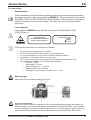
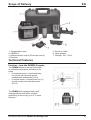
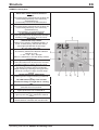
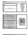
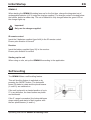
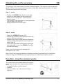
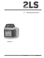
EN
Operating Instructions
GEMINI G
0 6 1 3 4 0 -1 0 4
06. 09. 2011
General Notes
EN
For your safety
Documentation
Please familiarise yourself with these operating instructions and the safety information
it contains before you start to work with the GEMINI G . These are based on the current
EN 60825-1:2007 and IEC/TR 60825-14:2004 standards. Observing these instructions
and this information ensures safe working. The laser may only be used by trained
personnel!
Laser radiation
Laser radiation GEMINI G laser class 3R according to DIN EN 60825-1:2007
(VDE 087 part 1).
LASER RADIATION
AVOID DIRECT EYE EXPOSURE!
CLASS 3R LASER PRODUCT
DIN EN 60825-1:2007
P d 5mW
O: 532 nm
M d 1,5 mrad
General safety instructions for handling laser radiation:
x
x
x
x
x
x
Prevent direct eye exposure to the beam!
Do not direct the beam at other people or into public areas!
To prevent reflections, do not point the laser at reflective surfaces.
If possible, do not operate the laser at eye level!
The housing of the laser may be opened by trained service technicians only!
The emitted laser radiation has the following properties:
- Power P d 5mW
- Wavelength O: 532 nm
- Beam divergence M d 1.5 mrad
- Stationary laser dot: CW laser
- Rotating laser dot: Laser pulse with f: 1Hz ... 10Hz
Warning signs
Never remove the warning signs on the unit.
For users in Germany:
Please note and following the guidelines of the professional/trade association with liability for
industrial safety and insurance (Berufsgenossenschaftliche Richtlinie) BGI832 on the operation
of laser equipment: It is recommended that operation of a class 3R laser be registered with the
responsible professional/trade association (Berufsgenossenschaft) (BGI 832, Section 2.5).
Operating Instructions GEMINI G Rotating Laser
10
General Notes
EN
Intended use
Use
The GEMINI G is suitable for marking heights, for aligning, plumbing, levelling and for
carrying out similar work. The unit can be used indoors and outdoors.
Repair
Repairs may only be carried out by an authorised customer service agent. Never open
the unit yourself; doing so cancels the warranty.
Careful handling
The GEMINI G is a sensitive, high-precision instrument and should therefore be handled
with appropriate care. Never store the unit in the case if it is wet.
The environment
Disposal
Dispose of the unit in accordance with the applicable materials recycling regulations.
Batteries/rechargeable batteries
Batteries/rechargeable batteries are hazardous waste and may not be put into domestic
waste. They must be properly disposed of according to the respective national
guidelines.
Note on green laser diodes
Green laser diodes react sensitively to temperature fluctuations. They can have an input
effect, as a result of which the full output is not reached until approx. 15min after
switching on. For technical reasons, the output of green laser diodes can drop at low
temperatures.
Operating Instructions GEMINI G Rotating Laser
11
Scope of Delivery
1
2
3
4
Transportation case
GEMINI G
Infrared remote control (IR remote control)
Receiver
EN
5 Receiver holder
6 Laser glasses
7 Charger, 100 – 240 V
Technical Features
Function - how the GEMINI G works
The GEMINI G can be set up horizontally
or vertically and projects according to its
setup
o in horizontal mode, a horizontal laser
line (H) as well as plumb points
upwards and downwards (L1/L2)
o in vertical mode, a vertical laser line (V)
as well as two horizontal laser dots
(L1/L2)
The GEMINI G is equipped with a selflevelling feature and levels out tilted
positioning of the unit by up to 5° in each
direction.
Operating Instructions GEMINI G Rotating Laser
12
Structure
EN
GEMINI G control panel
1
2
3
4
5
6
7
8
9
10
11
12
"Move laser in anti-clockwise direction"
button
Press button/keep pressed: Moves the laser dot
incrementally/constantly or the scan array
(limited laser line)
incrementally in an anti-clockwise direction.
"Move laser in clockwise direction" button
Press button/keep pressed: Moves the laser dot
incrementally/constantly or the scan array
(limited laser line)
incrementally in a clockwise direction.
"x-axis tilt adjustment" buttons
These two buttons can be used in the "manual
levelling" position to set the tilt of the x-axis.
"Scan angle
(limited laser line)" button
Button is only active in "Rotational speed = 0"
mode. It consecutively switches the various
scan angles (limited laser line) through:
0° – 6° – 20° – 50° – 90°.
"Rotational speed" button
Successively switches the different rotational
speeds on or off:
0 – 60 – 120 – 300 – 600 rpm.
When it is switched on, the laser always rotates
with 600 rpm.
"y-axis tilt adjustment" buttons
These two buttons can be used in the "manual
levelling" position to set the tilt of the y-axis.
"Height monitoring" button
This button is used to switch on automatic
height monitoring. Following a strong jolt which
results to a change in height, the laser stops
rotating.
"Height monitoring" LED display
Flashes green if height monitoring is switched
on.
The LED flashes quickly if the unit has
identified a change in height due to a strong
jolt.
ON/OFF button
Switches the unit on and off.
"Equipment On" LED display
Lights up red if the unit is switched on.
"Levelling" LED display
Lights up red if the unit is switched to manual
mode.
"Levelling" button
Switch between automatic and manual mode.
Operating Instructions GEMINI G Rotating Laser
13
Structure
EN
Control panel of the IR remote control
The button symbols and functions correspond to the
comparable buttons on the control panel of the GEMINI G ,
see page 13.
Exception:
13
"Send" LED display
Briefly lights up when buttons 4, 5 or 12 are pressed.
Flashes as long as buttons 1, 2, 3 or 6 are pressed.
Control panel receiver
1
2
3
4
5
6
"ON/OFF" button
Switches the receiver on and off.
"Acoustic signal" button
Switches the acoustic signal quied/loud .
"Detector field sensitivity" button
Switches the sensitivity between coarse/fine .
LCD display "Acoustic signal"
Lights up corresponding to "acoustic signal quied/loud".
LCD display "Target"
Lights up if the laser line is located precisely at the level of
the zero line. In addition, a continuous tone is emitted.
Detector field
7
"Coarse sensitivity" LCD display
Lights up if the sensitivity is set to "coarse".
8
"Fine sensitivity" LCD display
Lights up if the sensitivity is set to "fine".
9
LCD display "Lower"
Lights up if the laser line is within the sensor window but
below the zero line. A slow, intermittent tone is also emitted.
10
11
LCD Display "Higher"
Lights up if the laser line is within the sensor window but
above the zero line. A rapid, intermittent tone is emitted.
LED display "Battery"
Indicates the battery's state of charge.
Operating Instructions GEMINI G Rotating Laser
14
Initial Startup
EN
GEMINI G
When starting the GEMINI G rotating laser up for the first time, charge the integrated set of
rechargeable batteries (4.8 V) using the charger supplied. The charger socket is located below
the handle, behind a rubber cap. The set of batteries is fully charged when the green LED on
the charger lights up.
Important!
Only use the charger supplied.
IR remote control
Insert the 2 batteries supplied (type AAA) in the IR remote control.
Ensure pole direction is correct!
Receiver
Insert the battery supplied (type 9V) in the receiver.
Ensure pole direction is correct!
Starting up the unit
When using on site, set up the GEMINI G according to the application.
Self-levelling
The GEMINI G has a self-levelling feature.
This self-levelling feature is switched on by
pressing the ON/OFF button. The horizontal
beam (H) starts to rotate and the plumb beams
(L1 and L2) are switched on.
If the unit is placed in a slanted position of up to
5° in any direction, the laser beams are plumb
and horizontal.
If the 5° range is exceeded, the horizontal beam
stops rotating and starts to flash together with
the two plumb beams (L1 and L2).
Operating Instructions GEMINI G Rotating Laser
15
Specifications
Model
Ref. No.
Laser configuration
EN
Battery life
Operating temperature
Class of protection
Dimensions
Weight
GEMINI G
471920-613-104
1 laser dot, rotating from 0° to 360°
– 1 laser line due to rotating laser dot
– 1 scan array (limited line), see scan angle
1 plumb point upward and downward
0, 60, 120, 300, 600 rpm
0°, 6°, 20°, 50°, 90°
± 0.1 mm/m
< 30 sec.
BSW 5/8" on unit
300 m (diameter) with receiver
532nm
3R
< 5 mW
±5° to the horizontal and vertical axis, motorised
Set of NiMH 4.8 V rechargeable batteries, including charger
Battery capacity approx. 3800 mAh
approx 15 h
+5 °C to +35 °C
IP 54
B 150 mm / D 200 mm / H 190mm
2.1 kg
Model
Range
Power supply
Dimensions
Weight
Infrared remote control
Approx. 25 m
Batteries: 2 x 1.5 V (AAA)
B 46 mm / D 24 mm / H 111 mm
0.07 kg
Model
Detector length
Sensitivity, coarse/fine
Display
Receiver
40 mm
switchable, ±2 mm / ±1 mm
LCD display on front/rear and acoustic signal
(can be switched off)
Batteries: 1 x 9 V
up to 70 h
after approx. 20 min
M5 thread on the rear
W 64 mm / D 25 mm / H 135 mm
0.16 kg
Rotational speed
Scan angle
Levelling accuracy
Levelling time
Thread
Working range
Wavelength
Laser class
Output
Self-levelling range
Power supply
Power supply
Battery life
Automatic switch-off
Fixing
Dimensions
Weight
We reserve the right to make technical changes without notice.
Operating Instructions GEMINI G Rotating Laser
16
Checking the unit's accuracy
EN
The accuracy of the laser beam should be checked regularly. This requires a free measuring
length of 30 m. Four measurements are taken in total (two measurements each in X/Y axis).
The check is carried out in two steps.
Step 1 – x-axis
• Position the GEMINI G as shown on the right,
along the x-axis marked on the housing and
switch on the rotating laser. The laser beam
starts to rotate.
• The position of the laser beam is now determined
with the help of the receiver.
• Mark position A of the laser beam.
Step 2 – x-axis
• Rotate the GEMINI G through 180°.
• Repeat the preceding steps again and mark the
position B of the laser beam.
• Measure the plumb vertical distance H between
marking A and marking B, this can be above or
below mark A.
• If the measured distance H between marking A
and marking B < 6 mm, the GEMINI G is within
the tolerance range.
Steps 1 and 2 now have to be repeated as
described for the Y-axis.
Note: If the plumb measured distance H between marking A and marking B is outside the
tolerance range, the GEMINI G must be checked by an authorised customer service.
Function - how the receiver works
The receiver's sensor window detects the position
of the laser dot (laser line) and therefore enables
work
• on weak reflecting or dark surfaces
• outdoors
• in poor visibility, e.g. in the event of strong
sunshine.
Operating Instructions GEMINI G Rotating Laser
17