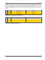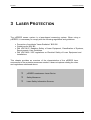
1
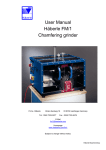
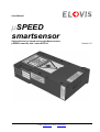
User Manual µSPEED smartsensor Optical Device for Speed and Length Measurement µSPEED-smart-Sx and –smart-ECO-Sx Version 1.0 ELOVIS GmbH Karl-Friedrich-Str. 14-18 D-76133 Karlsruhe Tel.: +49 (0) 721 933823 0 Fax: +49 (0) 721 933823 23 E-Mail: [email protected] Home: www.elovis.de DEAR CUSTOMER Thank you for giving us and our products your trust. Kindly read the operating instructions carefully. This is a prerequisite to achieve faultless initial operation and functioning of the unit. Before unpacking the equipment, please also read the following paragraphs. This unit is a class IIIB laser product and complies with EN60825-1:2001. Complies with 21 CFR 1040.10 and 1040.11 except for deviations pursuant to Laser Notice No. 50, dated July 26, 2001. The following safety features required to comply with the Bureau of Radiological Health Class IIIB laser requirements are included: Laser indicator light on controller and laser INVISIBLE LASER RADIATION AVOID DIRECT EXPOSURE TO BEAM INVISIBLE LASER RADIATION WHEN OPEN LASER CLASS 3B WAVELENGTH 780nm CW OUTPUT POWER 25mW EN 60825-1:2001 Do not open! Delayed laser startuplaser indicator light on prior to laser radiation Laser beam blocking device Interlock capability for remote shut-off No serviceable parts inside! Specifications are subject to change without notice. CAUTION! Every operation, adjustment or servicing that does not exactly conform to the indications given in this instruction manual can result in dangerous irradiation from the laser. Servicing of laser appliances should be performed by suitably qualified personal only. The lasers used do not emit X-rays or other harmful radiations. You should however use proper caution when handling them. ID308 II Remarks about Laser Classes Equipment with laser light sources is classed according to its AEL (Accessible Emission Limit). A laser belongs to one of the classes 1, 2, 3A, 3B or 4. It is important to know that the accessible radiation is the radiation emitted by the equipment when it is operating. The overall laser power in both partial beams of the µSPEED measuring unit does not exceed 25 mW. The laser gauge thus belongs to the low end of laser class 3B. Eye damage could occur in the laser area and under unfavourable conditions. The laser area is shown in chapter 4.3. It is possible to avoid the danger by taking suitable precautions such as those in chapter 3. A danger only exists when looking directly into the beam or when the reflected beam falls into the eye. Any surface that does not cause a sharp reflection of the beam can be looked at without any risk. This also applies to bright reflecting surfaces not made of metal, e.g. cable insulation or foil. A laser reflection from a metal surface that diffuses light and with a curvature radius < 5 mm, e.g. wire, is also harmless. Exposure, even a direct one, of the skin to the radiations is also harmless. The complete characteristics of the µSPEED measuring unit are given in chapter 3.1.1. Laser Type Used Maximum power Wavelength Laser class 25 mW 780 nm 3B Table 1: Laser Data Other properties of the laser gauge, how to set up correctly the measuring unit, as well as references and source of the regulations and guidelines for laser protection are to be found in chapter 3: Description of Laser Protection. PRECAUTION MEASURES DURING OPERATION Never use a measuring unit when it is not mounted! Please consider the information about the laser area in chapter 3.2. A detailed description on how to mount correctly a measuring unit is to be found in chapter 3 (Laser Protection). - Kindly pay attention to the following regulations when using laser equipment: - Prevention of accidents "Laser Radiation" BGV B2 - Guidelines for BGV B2 - DIN VDE 0837: Radiation Safety of Laser Equipment, Classification of Systems, Requirements, User Guidelines - DIN VDE 0836: VDE regulations on Electrical Safety of Laser Equipment and Installations Always switch off the laser when work is performed on the measuring unit! Further, specific safety aspects are listed in the corresponding chapters. ELOVIS GMBH is not responsible for accidents due to the inappropriate use of the equipment and to ignoring laser protection regulations! ID308 III PROHIBITED USE The user, owner, to be called here "the customer" must be aware of the following use restrictions: 1. The customer may use the "products" only for their intended use and must not divert them from their initial purpose. This concerns in particular possible harm to persons caused by disregarding laser safety guidelines. 2. The customer must not open the "products". 3. The customer must not modify, extend, transform, copy or decompile the hardware and software contained in the "products". 4. The customer agrees not to duplicate the product in any way whatsoever. The list does not pretend to be complete! In case of infringement, the ELOVIS GMBH rejects all claims for damages but it shall itself make such claims. WARRANTY The equipment has been carefully tested both mechanically and electrically prior to shipment. It has also been verified, as far as possible, that the equipment is in good working order. We guarantee good working of the equipment for a period of 12 months beginning on the day the equipment is ready to be shipped at our plant. We promise to repair or replace at will, as quickly and reasonably as possible, any parts which are proven to be faulty in design, material or workmanship. Warranty begins from the moment, the equipment is ready to be shipped at our plant. In cases where we undertake assembly and/or initial operation, the warranty begins from the day of initial operation. Our liability is limited to direct damages only. Our warranty shall not cover replacements or repairs which are due to normal wear and tear. Faulty construction of buildings Likewise excepted from the warranty are: – faulty or negligent maintenance – disregard of operating instructions – overloading – use of unsuitable materials – incorrect assembly works – faulty electrical connections – acts of God, and any other cause beyond our control ► Our "General Terms and Conditions of Sale" (ELOVIS.AGB), of which the above text is an excerpt, are binding for all warranty cases. Imprint ELOVIS GmbH, Karl-Friedrich-Str. 14-18, D-76133 Karlsruhe, Germany File: e_manual-uSpeed-Sensor.doc Date of memorization: 08.02.2008 16:06:00 Size: 1107968 Byte Update number: 117 Dokument ID: 18 ID308 IV Contents 1 Introduction .............................................................................................. 1 1.1 µSPEED-smartsensor .........................................Fehler! Textmarke nicht definiert. 1.2 Technical Data....................................................................................................... 2 1.3 Scope of Delivery.................................................................................................. 2 1.4 Installation and Commissioning.......................................................................... 3 2 Interfaces .................................................................................................. 5 2.1 mechanical Interface ............................................................................................ 6 2.2 Electrical Interface ................................................................................................ 6 2.2.1 Voltage ......................................................................................................... 6 2.2.2 Emergency Shut-off / Laser Interlock ........................................................... 6 2.2.3 Communication Interfaces............................................................................ 6 2.2.4 Configuration Alternatives ............................................................................ 8 2.2.5 Pin Assignment ............................................................................................ 8 3 Laser Protection..................................................................................... 11 3.1 µSPEED-smartsensor Laser Device .................................................................. 12 3.1.1 Characteristics............................................................................................ 12 3.1.2 Saftey feature ............................................................................................. 12 3.2 Safety Measures.................................................................................................. 13 3.3 Laser Safety Information Sources in Germany ................................................ 13 3.4 Laser Safety Information Sources outside Germany....................................... 13 4 Diagrams and Drawings ........................................................................ 14 4.1 Pin Identification of the Binder Flange Connector........................................... 15 4.2 Dimensional drawing of µSPEED-smartsensor................................................ 15 4.3 Laser Area ........................................................................................................... 16 4.4 Warning Labels ................................................................................................... 17 4.5 Mechanical Shutter (optional)............................................................................ 18 ID308 V ELOVIS 1 Introduction 1 INTRODUCTION ID308 µSPEED-smartsensor Technical Data Scope of Delivery Installation and Commissioning 1 ELOVIS 1.1 1 Introduction µSPEED-SMARTSENSOR General description The measuring devices type µSPEED-smartsensor are laser sensors based on the Doppler effect and are used for non-contact measurement of length and velocity of surfaces with diffuse reflection. They provide extremely accurate measurement without markings or rods. This measuring equipment is thus particularly suitable for its use in process control and quality assurance. It allows the optimization of cutting operations, positioning and dosing in the case of flat or rope-like material such as paper, metal, wood, textile, plates, sheets, wires and cables. Function The measurement is non-contact and therefore completely free of wear and tear. It is performed by scanning the product from a laser-based measuring unit that projects a striated pattern on the object. The measured object backscatters the laser beam into the measuring unit. The frequency of the backscattered light is directly proportional to the measured object's velocity. 1.2 TECHNICAL DATA Technical data of the µSPEED-smartsensor are listed in the following Table 1. Speed measuring range (dependend on type of sensor) 2 m/min – 2400 m/min Accuracy < 0,05 % for length more than 20m Stand-off distance (depth of field) 120 mm (+/- 5mm [+/- 10mm]) 240mm (+/- 10mm [+/- 20mm]) Interfaces 1x RS232 oder RS485 & 1x Multifunktion Voltage 24 V / 3 Watt Degree of protection IP 67 Laser classification 3B (780nm) Table 1: Technical data µSPEED-smartsensor 1.3 SCOPE OF DELIVERY The standard scope of delivery of the µSPEED-smartsensor is: ID308 Sensor head (in the following µSPEED-smartsensor) Sensor cable Plastic screws and plastic plate for insulated installation User manual 2 ELOVIS 1.4 1 Introduction INSTALLATION AND COMMISSIONING Check. 1. Please check whether you received all components listed in the scope of delivery. 2. Please check every single delivery component. If you see damages or in case of missing components, please do not set the unit into operation, but contact: ELOVIS GmbH, Karl-Friedrich Str. 14-18, D-76133 Karlsruhe, Germany Tel.: +49 (0) 721 / 933 823-0; Fax: +49 (0) 721 / 933 823-23 Mounting µSPEED-smartsensor. Danger of eye damage from class 3B laser! Never use the measuring unit when it is not mounted! 1. The alignment of the measuring unit has to be perpendicular to the measured object. It should be mounted at an angle of 90 degree and at a distance of 120mm (+/- 3mm to +/-5mm) or 240 mm (+/- 10mm) from the measured object (see Figure 1). The rules and regulations of laser protection must be followed (see chapter 3). Figure 1: Mounting tolerances and alignment of µSPEED-smartsensor 2. µSPEED-smartsensor must be mounted electrically isolated (no contact with machinery ground). The PVC plate and plastic screws which are included in the scope of delivery, should be used for this purpose. Electrical connection of µSPEED-smartsensor. 1. Connect the delivered sensor cable with the µSPEED-smartsensor. 2. Interconnect/wire the other end of the sensor cable according to the designated functions. 3. Interconnect/wire the emergency shut-off input Fehler! Verweisquelle konnte nicht gefunden werden.according to the laser protection directions (see detailed information in chapter 3.1.2). The shut-off input has to be connected to a key switch (which is not ID308 3 ELOVIS 1 Introduction part of the scope of delivery), whose key can only be pulled out during laser off status, and has to be connected additionally to one or more emergency shut-off devices. 4. Instead of 2. and 3.: Connect the other end of the sensor cable with the optional ELOVIS Speed-Box. The possibilities of wiring of the Speed-Box can be found in the in the associated Speed-Box manual. ID308 4 ELOVIS 2 Interfaces 2 INTERFACES The µSPEED-smartsensor is delivered with a connector plug, which provides all signals and which is used for power supply in addition. ID308 Mechanical Interface Electrical Interface 5 ELOVIS 2.1 2 Interfaces MECHANICAL INTERFACE The sensor head of µSPEED-smartsensor is equipped with a flange connector of the company Binder (Germany). series: 423 number of poles: 12 type: 09-0131-68-12 degree of protection: IP67 The following types of sockets (female) can be used for the above mentioned flange connector: straight: type: 99-5630-15-12 bent: type: 99-5630-75-12 The sensor cable, which is part of the scope of delivery, has on its end to the µSPEEDsmartsensor a fitting socket and on the other end a connector 15-pole standard Sub-D. 2.2 ELECTRICAL INTERFACE 2.2.1 VOLTAGE supply voltage: 18-30V (nominal 24V) controlled wattage: max. 3W pin assignment see 2.2.5. 2.2.2 EMERGENCY SHUT-OFF / LASER INTERLOCK type of signal: one-sided (against signal ground) min. signal voltage: 0V max. signal voltage: 30V switching voltage: upward: approx. 19V downward: approx. 7V hysteresis: approx. 12V pin assingment see 2.2.5. status possibilities: input voltage < switching voltage: emergency shut-off / laser protection input voltage > switching voltage: standard operation 2.2.3 COMMUNICATION INTERFACES There are two separate, equitable interfaces for communication. One always existent communication interface and one flee configurable multifunction interface. ID308 6 ELOVIS 2 Interfaces 2.2.3.1 CONFIGURATION INTERFACE (RS-485 / RS-232) Always existent interface. The mode (RS-485 or RS-232) is configurable. interface to RS-485 or RS-232 min. baud rate: 1200 baud Max. baud rate: 460800 baud data bit: 7 or 8 parity: none, even, odd pin assignment see 2.2.5. 2.2.3.2 MULTIFUNCTION INTERFACE The multifunction interface consists of three differential pairs of five Volt. These pairs according to the configuration (see 2.2.4) form a RS-485- ,RS-422- or SSIinterface, I/O ports or a combination thereof. Interfaces which can be implemented are described in the following. RS-485 Possible in configuration K3, K4 and K7 (see 2.2.4). Interface to RS-485 min. baud rate: 1200 baud max. baud rate: 460800 baud data bits: 7 or 8 parity: none, even, odd pin assignment see 2.2.5. RS-422 Possible in configuration K5 and K8 (see 2.2.4). Interface to RS-485 min. baud rate: 1200 baud max. baud rate: 460800 baud data bits: 7 or 8 parity: none, even, odd pin assignment see 2.2.5. SSI Possible in configuration K6 and K9 (see 2.2.4). ID308 standard SSI-interface SSI-Clock input to RS-422 input specification SSI-Data outnput to RS-422 output specification max. output frequency: 1MHz pin assignment see 2.2.5. 7 ELOVIS 2 Interfaces Quadrature / Pulse output Possible in configuration K1 (quadrature output with dead center position), K2 and K3 (quadrature output without dead center position), K4, K5 and K6 (pulse output) (see 2.2.4). ouput to RS-422 output specification max. output frequency: 1MHz max. output frequency for one permille frequency accuracy: 20kHz max. output frequency for one percent frequency accuracy: 200kHz pin assignment see 2.2.5. I/O Possible in configuration K2, K4, K8 and K9 (one I/O-Port), K7 (two I/O-Ports), K10 (three I/O-Ports) (see 2.2.4). input to RS-422 input specification ouput to RS-422 output specification pin assingment see 2.2.5. 2.2.4 CONFIGURATION ALTERNATIVES Configuration Description K1 Quadrature output with Dead Center Position (A/B/N) K2 Quadrature output wirhout Dead Center Position (A/B) & 1x I/O K3 Quadrature output without Dead Center Position (A/B) & RS-485 K4 Pulse output (A) & RS-485 & 1x I/O K5 Pulse output (A) & RS-422 K6 Pulse output (A) & SSI K7 RS-485 & 2x I/O K8 RS-422 & 1x I/O K9 SSI & 1x I/O K10 3x I/O Table 2: Configuration Alternatives 2.2.5 PIN ASSIGNMENT Pin assignment up to output configuration: ID308 8 ELOVIS 2 Interfaces Pin Signal K1 K2 K3 K4 K5 K6 K7 K8 K9 K10 M VCC X X X X X X X X X X G PGND X X X X X X X X X X J SGND X X X X X X X X X X H EmS-Off X X X X X X X X X X F Config A X X X X X X X X X X E Config B X X X X X X X X X X A I/O1+ A A A A A A I/O I/O I/O I/O K I/O1- A/ A/ A/ A/ A/ A/ I/O I/O I/O I/O L I/O2+ B B B I/O 422-R+ SSI-C+ I/O 422-R+ SSI-C+ I/O B I/O2- B/ B/ B/ I/O 422-R- SSI-C- I/O 422-R- SSI-C- I/O D I/O3+ N I/O 485+ 485+ 422-T+ SSI-D+ 485+ 422-T+ SSI-D+ I/O C I/O3- N/ I/O 485- 485- 422-T- SSI-D- 485- 422-T- SSI-D- I/O Table 3: Binder Flange Connector Pin Signal K1 K2 K3 K4 K5 K6 K7 K8 K9 K10 14 VCC X X X X X X X X X X 15 PGND X X X X X X X X X X 12 SGND X X X X X X X X X X 13 EmS-off X X X X X X X X X X 8 Config A X X X X X X X X X X 7 Config B X X X X X X X X X X 2 I/O1+ A A A A A A I/O I/O I/O I/O 1 I/O1- A/ A/ A/ A/ A/ A/ I/O I/O I/O I/O 4 I/O2+ B B B I/O 422-R+ SSI-C+ I/O 422-R+ SSI-C+ I/O 3 I/O2- B/ B/ B/ I/O 422-R- SSI-C- I/O 422-R- SSI-C- I/O 6 I/O3+ N I/O 485+ 485+ 422-T+ SSI-D+ 485+ 422-T+ SSI-D+ I/O 5 I/O3- N/ I/O 485- 485- 422-T- SSI-D- 485- 422-T- SSI-D- I/O Table 4: Pin assignment Sub-D Connector ID308 Yellow: Green: Orange: Blue: Power supply Red-off/Laser protection – emergency shut-off Configuration interface Multifunction interface 9 ELOVIS 2 Interfaces Pair I/O1, I/O2 and I/O3, as well as the configuration interface in RS-485 Mode can in each case be configurated with a terminating impedance (load resistance) of 120 Ohm effectively. Depending on the kind of mode, the configuration interface is assigned as follows: Pin Signal RS-232 Mode RS-485 Mode F Config A RS-232-TXD RS-485+ E Config B RS-232-RXD RS-485- Table 5: Pin assignment Binder Flange Connector Pin Signal RS-232 Mode RS-485 Mode 8 Config A RS-232-TXD RS-485+ 7 Config B RS-232-RXD RS-485- Table 6: Pin assignment Sub-D Connector ID308 10 ELOVIS 3 Laser Protection 3 LASER PROTECTION The µSPEED sensor system is a laser-based measuring system. When using a µSPEED, it is necessary to comply with the following regulations and guidelines: Prevention of accidents "Laser Radiation" BGV B2 Guidelines for BGV B2 DIN VDE 0837: Radiation Safety of Laser Equipment, Classification of Systems, Requirements, User Guidelines DIN VDE 0836: VDE regulations on Electrical Safety of Laser Equipment and Installations This chapter provides an overview of the characteristics of the µSPEED laser sensors and of the protection measures needed. It does not replace reading the rules and regulations mentioned above. ID308 µSPEED-smartsensor Laser Device Safety Measures Laser Safety Information Sources 11 ELOVIS 3.1 3 Laser Protection µSPEED-SMARTSENSOR LASER DEVICE 3.1.1 CHARACTERISTICS The overall laser power in both partial beams of the µSPEED measuring unit does not exceed 25 mW. The laser gauge thus belongs to the low end of laser class 3B. Eye damage could occur in the laser area and under unfavourable conditions. The laser area is shown in chapter 4.3. It is possible to avoid the danger by taking suitable precautions such as those in chapter 3. A danger only exists when looking directly into the beam or when the reflected beam falls into the eye. Any surface that does not cause a sharp reflection of the beam can be looked at without any risk. This also applies to bright reflecting surfaces not made of metal, e.g. cable insulation or foil. A laser reflection from a metal surface that diffuses light and with a curvature radius < 5 mm, e.g. wire, is also harmless. Exposure, even a direct one, of the skin to the radiations is also harmless. The µSPEED-smartsensor Laser Data are listed in the following Table 7. Laser class 3B Visible laser radiation Output power at the intersecting point of the beams 780 nm (red) < 25 mW Power of a partial beam Spot diameter Max. irradiation up to 360 mm behind the output aperture (both beams) < 12,5 mW > 0.5 mm < 400 W/m2 Max. irradiation at 360 mm or more behind the output aperture (one beam) < 200 W/m2 Max. irradiation at 20 m or more behind the output aperture < 25 W/m2 Divergence angle horizontal 1.6 mrad vertical 0.8 mrad Table 7: µSPEED-smartsensor Laser Data 3.1.2 SAFTEY FEATURE µSPEED-smartsensor has a special safety feature: Without wiring the emergency shut-off input (see 2.2.2) the laser is always shut-off. This shut-off input has to be connected with a key switch (which is not part of the scope of delivery), whose key can only be pulled out during laser off status, and has to be connected additionally to one or more emergency shut-off devices. ID308 12 ELOVIS 3.2 3 Laser Protection SAFETY MEASURES The following protection measures for avoiding eye damage should apply when the µSPEED measuring unit is operating: 1. The measuring unit should be solidly fastened before operating it. It is necessary to ensure that the laser beam does not freely propagate through the area by the use of the laser tube and in addition by placing a laser blocking device (as shown in chapter 4.3) e.g. an opaque plate with diffuse reflection. 2. If the measuring unit is not fastened, the unit has to be switched off. If this is not possible the mechanical shutter has to be closed as shown in chapter 4.5. 3. The 10 cm area around the beam axis is to be signalled as a laser area. In the laser area, the threshold for direct eye irradiation is exceeded. It is therefore necessary to prevent anybody from manipulating plane reflecting surfaces or optical instruments in the laser area. The laser area ends either where the beam is blocked by a target with diffuse reflection or – when there is no such target – at a distance of 20 m. 4. A person responsible for laser protection should be charged in writing to supervise the operation of the laser equipment. 5. The employer’s liability insurance association or the equivalent organization should be informed prior to commissioning of the µSPEED that equipment including a laser of class 3B will be operated. 6. The exact regulations can be found in BGV B2. 3.3 LASER SAFETY INFORMATION SOURCES IN GERMANY The referred to regulations, guidlines and instructions at the beginning of this document as well as in this chapter can be purchased at a bookselling trade or under the following addresses in Germany: Carl Heymanns Verlag KG, Luxemburgerstr. 449, 50939 Köln Berufsgenossenschaft für Feinmechanik und Elektrotechnik, Gustav-HeinemannUfer 130, 50968 Köln 3.4 LASER SAFETY INFORMATION SOURCES OUTSIDE GERMANY Users who operate the µSPEED-smartsensor outside Germany: Please be aware that you have to inform yourself about the legal and official restrictions of your individual country, which can be different from the things mentioned in this manual. ELOVIS GmbH is not responsible for inappropriate use of the equipment and to ignoring laser protection regulations of the particular country! You may ask also for the assistance of our country sales agent. ID308 13 ELOVIS 4 Diagrams and Drawings 4 DIAGRAMS AND DRAWINGS ID308 Pin Identification of the Binder Flange Connector Dimensional drawing of µSPEED-smartsensor 14 ELOVIS 4.1 4 Diagrams and Drawings PIN IDENTIFICATION OF THE BINDER FLANGE CONNECTOR Figure 2: Pin Identification of the Binder Flange Connector 4.2 DIMENSIONAL DRAWING OF µSPEED-SMARTSENSOR 39 23,5 94 80 Measurement Volume LASERSTRAHLUNG NICHT DEM STRAHL AUSSETZEN LASER KLASSE 3B Messvolumen 32,5 Reference Edges Bezugskanten 18 78 138 154 120 Befestigungslöcher Durchgangslöcher M5 unten Gewinde M6x12 Mounting Holes (throughholes) Figure 3: Dimensional drawing of µSPEED-smartsensor (all measures in mm) Drawing shows µSPEED device with 120mm stand-off distance; Devices with 240mm stand-off distance see chapter 4.3 below. ID308 15 ELOVIS 4.3 4 Diagrams and Drawings LASER AREA The laser area is the zone which is dangerous if looking directly into the laser beam. It does not show the danger by reflected beam. The danger for looking directly into the laser beam can be reduced by the use of the optional laser tube and by installing a beam blocker device as shown in the following sketch (a) for 120mm; (b) for 240mm stand off distance. ID308 16 ELOVIS 4.4 4 Diagrams and Drawings WARNING LABELS The warning labels prescribed by EN60825 are affixed to the µSPEED measuring unit. ID308 17 ELOVIS 4.5 4 Diagrams and Drawings MECHANICAL SHUTTER (OPTIONAL) Measuring Unit including mechanical shutter Use of mechanical shutter ID308 18