1
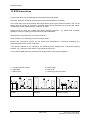
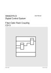
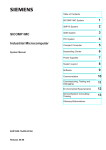
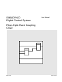
SIMADYN D
Digital Control System
User Manual
Fiber-Optic Rack Coupling
CS22
Edition 05.95
DK No. 237841
User Manual, Fiber-Optic Rack Coupling CS22
Edition
1
Status
Fiber-Optic Rack Coupling CS22
Copying of this document and giving it to others and the use or
communication of the contents thereof is forbidden without express
authority. Offenders are liable to the payment of damages. All rights
are reserved in the event of the grant of a patent or the registration of
a utility model or design.
We have checked the contents of this Manual to ensure that they
coincide with the described hardware and software. However,
deviations cannot be completely ruled-out, so we cannot guarantee
complete conformance. However, the information in this document is
regularly checked and the necessary corrections included in
subsequent editions. We are thankful for any recommendations or
suggestions.
05.95
Contents
Contents
Warning information................................ ................................ ................................ .................... 1
1. Ordering information ................................ ................................ ................................ ...............3
2. Description................................ ................................ ................................ .............................. 3
3. Board design................................ ................................ ................................ ........................... 3
4. Interfaces................................ ................................ ................................ ................................ 4
4.1. Backplane bus connection ................................ ................................ ....................... 4
4.2. Dignostics interface................................ ................................ ................................ ..4
4.3. Fiber-optic cables ................................ ................................ ................................ ....4
5. Application information................................ ................................ ................................ ............5
6. Additional components................................ ................................ ................................ ............5
7. Technical data................................ ................................ ................................ ......................... 6
8. STRUC L mask of the CS22 board in the master program................................ ...................... 6
9. Others................................ ................................ ................................ ................................ .....6
9.1. Attachments................................ ................................ ................................ .............6
9.1.1. Block diagram................................ ................................ ............................ 6
9.1.2. Dimension drawing ................................ ................................ .................... 6
9.2. Literature ................................ ................................ ................................ .................6
10. ESD instructions................................ ................................ ................................ .................... 8
Siemens AG Dk No. 237841
SIMADYN D Hardware User Manual
Edition 05.95
Warning information
Edition 05.95
Siemens AG Dk No. 237841
SIMADYN D Hardware User Manual
Warning information
NOTE!
The information in this Manual does not purport to cover all details or variations in equipment, nor to provide
for every possible contingency to be met in connection with installation, operation or maintenance.
Should further information be desired or should particular problems arise which are not covered sufficiently for
the purchaser’s purposes, please contact your local Siemens office.
Further, the contents of this Manual shall not become a part of or modify any prior or existing agreement,
committment or relationship. The sales contract contains the entire obligation of Siemens. The warranty
contained in the contract between the parties is the sole warranty of Siemens. Any statements contained
herein do not create new warranties nor modify the existing warranty.
Warning information
WARNING!
Electrical equipment has components which are at dangerous voltage levels.
If these instructions are not strictly adhered to, this can result in severe bodily
injury and material damage.
Only appropriately qualified personnel may work on this equipment or in its
vicinity.
This personnel must be completely knowledgeable about all the warnings and
service measures according to this User Manual.
The successful and safe operation of this equipment is dependent on proper
handling, installation, operation and maintenance.
Siemens AG Dk No. 237841
SIMADYN D Hardware User Manual
Edition 05.95
1
Warning information
Definitions
*
QUALIFIED PERSONNEL
*
DANGER
*
WARNING
*
CAUTION
*
NOTE
For the purpose of this User Manual and product labels, a „Qualified person“ is someone who is familiar with the
installation, mounting, start-up and operation of the equipment and the hazards involved. He or she must have
the following qualifications:
1. Trained and authorized to energize, de-energize, clear, ground and tag circuits and equipment in accordance
with established safety procedures.
2. Trained in the proper care and use of protective equipment in accordance with established safety
procedures.
3. Trained in rendering first aid.
For the purpose of this User Manual and product labels, „Danger“ indicates death, severe personal injury and/or
substantial property damage will result if proper precautions are not taken.
For the purpose of this User Manual and product labels, „Warning“ indicates death, severe personal injury or
property damage can result if proper precautions are not taken.
For the purpose of this User Manual and product labels, „Caution“ indicates that minor personal injury or
material damage can result if proper precautions are not taken.
For the purpose of this User Manual, „Note“ indicates information about the product or the respective part of the
User Manual which is essential to highlight.
CAUTION!
This board contains components which can be destroyed by electrostatic
discharge. Prior to touching any electronics board, your body must be electrically
discharged. This can be simply done by touching a conductive, grounded object
immediately beforehand (e.g. bare metal cabinet components, socket protective
conductor contact).
WARNING!
Hazardous voltages are present in this electrical equipment during operation.
Non-observance of the safety instructions can result in severe personal injury or
property damage.
It is especially important that the warning information in all of the relevant
Operating Instructions are strictly observed.
2
Edition 05.95
Siemens AG Dk No. 237841
SIMADYN D Hardware User Manual
Ordering information
1. Ordering information
CS22: 6DD1660-0BD0
Fiber-optic rack coupling CS22
2. Description
The CS22 communications board is the slave board for the rack coupling via fiber-optic cable. The
connection to the master board is inserted via two fiber-optic cable connections on the front panel.
Either a CS12, CS13 or CS14 board is used as master.
The address-, data- and control signals for accessing the master board memory are processed on the
CS22.
Data transfer between the processor boards and the CS22 is realized via the C bus. Thus, it can only
be used in subracks with L- and C bus.
The subrack with the CS22 can be considered to be the system slave. The basic sampling time and
alarm interrupt from the master board are received, which can be used to synchronize the slave
subrack.
3. Board design
The board provides the following hardware components.
Communications bus connection ( C bus, X1 )
Local bus connection ( L bus, X2 )
Two fiber-optic cable connections to the master board ( X5, X6 )
Receiving the basic sampling time and alarm interrupt from the C bus of the master board
Diagnostics interface for the logic analyzer
Siemens AG Dk No. 237841
SIMADYN D Hardware User Manual
Edition 05.95
3
Interfaces
4. Interfaces
4.1. Backplane bus connection
The connection to the subrack backplane buses is established via the 96-pin plug connector at slots
X1 and X2. The connection for the data-, address- and control bus as well as the +5 V power supply is
realized through connector X1, and the power supply signals as well as the +5 V and +15 V power
supply, via connector X2.
4.2. Dignostics interface
When a fault occurs, a logic analyzer can be connected-up through the 50-pin plug connector X4 in
order to simplify troubleshooting.
This interface is exclusively used to connect-up the logic analyzer and it may not be used for any
other purpose.
4.3. Fiber-optic cables
The fiber-optic cables to the master board are inserted at the two plug connectors X5 and X6 on the
front panel.
Glass fiber-optic cables are used. They use glass fibers, fiber type 62.5/125 µm ( core
diameter/sheath diameter). ST plug connectors are used.
The fiber-optic cable connection to the master depends on the master board used. The precise
connection assignments can be taken from the appropriate User Manuals ( CS12: /1/; CS13: /2/;
CS14: /3/ ).
The fiber-optic cables can be ordered as pre-assembled cables from the Siemens Automation Group.
For more detailed information regarding the ordering data, refer to Catalog „SINEC Industrial
Communication Networks, Catalog IK 10 . 1993 ".
The maximum cable length between the master- and slave board is 500 m.
4
Edition 05.95
Siemens AG Dk No. 237841
SIMADYN D Hardware User Manual
Application information
5. Application information
The board can be used in pure 32-bit systems and in mixed 16-bit- and 32-bit systems and in pure 16bit systems. Using a connector in the master program board mask, it is specified whether the memory
is in the extended address range or in the special periphery range. The memory is pre-set in the
extended address range.
Memory range
Memory size
Entry at the EMA connector
Extended address range
Special peripheral range
128 kbyte
32 kbyte
Y
N
When configuring, it should be observed that the entry at the EMA connector of the master board and
the associated CS22 EMA connector at the same. If the entry is different, at start-up, a
communications error will occur. This error is not identified when the master program is compiled.
The connectors in the master program board mask are used to specify as to whether the basic
sampling time and the alarm interrupt from the master board should be received. The board is preset
so that both signals are not received.
Function
Connector
Entry
Base sampling time not received
Base sampling time received
Alarm interrupt not received
Alarm interrupt received
TCR
TCR
ICR
ICR
N
Y
N
Y
If a fiber-optic cable is not inserted, the transmit- and receive modules must be protected using caps.
The board must be screwed tightly into the subrack to ensure perfect operation, even during start-up.
If the board is inserted in an adapter, the front panel must be connected with the frame housing
through a short cable.
It is not permissible that the board is inserted or withdrawn under voltage.
6. Additional components
Designation
Order No.
CS12 master board
CS13 master board
CS14 master board
6DD1660-0BA0
6DD1660-0BB0
6DD1660-0BC0
Siemens AG Dk No. 237841
SIMADYN D Hardware User Manual
Edition 05.95
5
Technical data
7. Technical data
INSULATION GROUP
AMBIENT TEMPERATURE
STORAGE TEMPERATURE
HUMIDITY RATING
ALTITUDE RATING
MECHANICAL STRESSING
PACKAGING SYSTEM
DIMENSIONS
BOARD WIDTH
WEIGHT
CURRENT DRAIN
A acc. to VDE 0110 Para. 13, Group 2
at 24 V DC, 15 V DC, 5 V DC
0 to +55 degrees, self-ventilated
-40 to + 70 degrees C
F acc. to DIN 40040
S acc. to DIN 40040
Installed in stationary but not necessarily vibration-free
equipment
ES 902 C
220 * 233.4 mm
1 slot in the subrack
0.4 kg
P5
0.5 A
P15
50 mA
8. STRUC L mask of the CS22 board in the master program
100
101
102
103
104
:CS22
"Fiber-optic rack coupling, CS22, C bus"
EMA
1C = Y
"Only P32 access permitted
( Y / N )"
TCR
1C = N
"Basic sampling time from the CS12 ( Y / N )"
ICR
1C = N
"Alarm interrupt from the CS12
( Y / N )"
*************************************************************************************
9. Others
9.1. Attachments
9.1.1. Block diagram
Block diagram
Fig. 1
9.1.2. Dimension drawing
Dimension drawing
3SE.465 660.9013.00 MB
9.2. Literature
6
/1/
User Manual
Fiber-optic rack coupling, CS12
/2/
User Manual
Fiber-optic rack coupling, CS13
/3/
User Manual
Fiber-optic rack coupling, CS14
Edition 05.95
Siemens AG Dk No. 237841
SIMADYN D Hardware User Manual
Others
C bus connector 96-pin ES902C
X1
L bus connector 96-pin ES902C
X2
SV
Addr. driver
Data driver
PS
Reset
Contr. signals Backplane code Board code
Program
address
decoder
Addr. driver
Data driver
P
Fiber-optic
cable contr.
Chip select
P
S
X5
S
X6
Fig. 1: Block diagram CS22
Siemens AG Dk No. 237841
SIMADYN D Hardware User Manual
Edition 05.95
7
ESD instructions
10. ESD instructions
Components which can be destroyed by electrostatic discharge (ESD)
Generally, electronic boards should only be touched when absolutely necessary.
The human body must be electrically discharged before touching an electronics board. This can be
simply done by touching a conductive, grounded object directly beforehand (e.g. bare metal cubicle
components, socket outlet protective conductor contact).
Boards must not come into contact with highly-insulating materials - e.g. plastic foils, insulated
desktops, articles of clothing manufactured from man-made fibers.
Boards must only be placed on conductive surfaces.
When soldering, the soldering iron tip must be grounded.
Boards and components should only be stored and transported in conductive packaging (e.g.
metalized plastic boxes, metal containers).
If the packing material is not conductive, the boards must be wrapped with a conductive packing
material, e.g. conductive foam rubber or household aluminum foil.
The necessary ESD protective measures are clearly shown in the following diagram.
a = Conductive floor surface
b = ESD table
c = ESD shoes
Seated
8
d = ESD overall
e = ESD chain
f = Cabinet ground connection
Standing
Edition 05.95
Standing / sitting
Siemens AG Dk No. 237841
SIMADYN D Hardware User Manual
ESD instructions
Siemens AG Dk No. 237841
SIMADYN D Hardware User Manual
Edition 05.95
9
ESD instructions
Drives and Standard Products
Motors and Drive Systems Group
Postfach 3269, D-91050 Erlangen
10
System-Based
Drive
Technology
Edition 05.95
Siemens AG Dk No. 237841
SIMADYN D Hardware User Manual