1
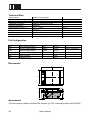
Strain Sensors DA40, DA54, DAdx, DA115Clip, DA120Clip Last update: 02.01.07 ME-Meßsysteme GmbH Neuendorftstr. 18a D-16761Hennigsdorf Tel.: +49 3302 559 282 Fax: +49 3302 559 141 Table of contents Strain Sensors DA40 and DA54............................................................................................3 Description.........................................................................................................................4 Dimensions........................................................................................................................5 Technical Data...................................................................................................................5 Pin configuration................................................................................................................5 Strain Sensor DAdX...............................................................................................................6 Description.........................................................................................................................6 Dimensions........................................................................................................................7 Technical Data...................................................................................................................7 Pin configuration................................................................................................................7 Installation instructions for DA40, DA54 and DAdX...............................................................8 Preparing the surface........................................................................................................8 Mixing the glue...................................................................................................................8 Preparing the strain sensor................................................................................................8 Gluing process...................................................................................................................8 Function check...................................................................................................................9 Cable..................................................................................................................................9 Pin configuration................................................................................................................9 DA120Clip............................................................................................................................10 Description.......................................................................................................................10 Advantages......................................................................................................................10 Technical Data.................................................................................................................12 Pin Configuration.............................................................................................................12 Dimensions......................................................................................................................12 Accessories......................................................................................................................12 2 User's Manual Strain Sensors DA40 and DA54 Measurement range: ±0.1 µm/m to ±1000 µm/m DA40 DA54-PUR DA54-M12 Illustration Dimensions 40mm x 26mm x 10mm 54mm x 30mm x 20mm 54mm x 30mm x 20mm Cable 5m 4x0.14, Ø3mm 5m 2x2x0.25, Ø6mm built-in jack M12 type 763 spring contact Accessories Illustration Adhesive EPY 150 (included in delivery) Adhesive M-Bond 30 (optional) Filling gun (optional) User's Manual 3 Description The areas of application for the strain sensors DA40 and DA54 are the high-resolution acquisition of forces and deformations on massive components e.g. of presses, lifting tools, tanks, steel supports, bridges as well as on connecting rods or pedestals of production machines. The retrospective installability make these strain sensors into universal, retro-fittable sensors for monitoring force and load. These strain sensors are durable and resistant to oil and moisture. The most favorable installation position is lateral to the direction of loading. The forces are then transmitted through the housing. Up to an strain of 1000µm/m, however, assembly longitudinal to the direction of the stress is possible without any limitation in the accuracy. The strain sensors DA40, DA54 and DadX are excellently suited for static and dynamic measurements. The strain sensors DA40 and DA54 only differ from each other in their dimensions and the fasteners (M4 or M6). The strain sensors DadX consist of two half-shells, which are mounted on pillars. They are available for diameters from 50mm to 250mm. The sensor DA54 is also available without a sink for mounting with concealed studs. The same performance features are achieved with these strain sensors in their robust and installation-friendly aluminum housing as with the direct application of strain gages . This includes a high resolution, very low drift symptoms and the possibilities for both static and dynamic measurement. The strain sensor contains a completely wired strain gage, which, when the strain sensor is being screwed on, is pressed on the component to be glued by a specially shaped pressing mechanism. The housing serves as a mounting frame for the strain gage application. The surface of the component must be ground and cleaned before screwing on the strain sensor in the area of the strain gage. The strain gage is permanently protected against moisture by means of a special, oil-resistant seal. The null balancing of the strain gage is carried out after the installation of the strain sensor by the strain gage measuring amplifier GSV-2. strains from 0.1µm/m onwards can be displayed. This corresponds to a mechanical stress of about 0.02N/mm2 on a component surface of steel. With the combination of strain sensor and measuring amplifier GSV-2, switching thresholds from about 1µm/m (corresponding to 0.2N/mm2) onwards can be monitored, if a null balancing is carried out periodically. For applications in weighing technology, an strain range of at least 30µm/m (6 N/mm2) is recommended, in order to achieve as low a drift as possible. 4 User's Manual Dimensions DA54 DA40 positive strain: <--> Technical Data Strain senor Length × width × height Fastening of strain gage Fastening of housing Material of housing Measurement range (εN) Input resistance Output resistance Insulation resistance Supply voltage Connection, 4-conductor tension / compression 40 × 26 × 10 or 54 x 30 x 10 adhesive sealing 2 × for M4 or M6 DIN 912 aluminum ±0,1 ... ±1000 350 ±0,7 350 ±0,7 > 5 ⋅ 109 2.5…10 5 mm × mm × mm μm/m Ohm Ohm Ohm V m Pin configuration +US -US +UD -UD DA40 red black green white positive bridge supply negative bridge supply positiver bridge output negative bridge output Optional: flange jack (spring contact) 1 2 4 3 (top view) pin number ME cabel DA54 brown white green yellow shield: transparent ME cabel designation 763 1 brown (+pink) red brown + supply (+Us) 2 white (+gray) black white - supply (-Us) 3 green green blue + signal (+Ud) 4 yellow white black - signal (-Ud) User's Manual 5 Strain Sensor DAdX Measurement range: ±0.1 µm/m to ±1000 µm/m Description The two half-shells of the strain sensor DAdX are mounted on pillars to measure the compressive force of e.g. punches or the pretensioning force of tools. This strain sensor is suitable, like the DA40 and DA54, for both static and dynamic force monitoring. As the strain sensor can be installed afterwards, it is a universal, retrofit sensor for monitoring force and load. The strain sensor is durable and resistant to oil and moisture. This strain sensor with aluminum half-shells achieves the same performance as the direct application of strain gages. This includes high resolution and low drift. Every half-shell contains a completely wired strain gage full bridge, which is pressed and glued on the corresponding component by a special pressing mechanism, when the strain sensor is being screwed on. The housing serves as a mounting frame for the strain gage application. Possible bending forces in the column are compensated by parallel connection of the two strain gage full bridges. Individual versions of the half-shells, e.g. with strain gage half-bridges in 90°-arrangement or with strain gage half-bridges for the torque measurement are possible. Before screwing on the strain sensor, the surface of the component must be ground and cleaned in the zone of the strain gage. The strain gage is durably protected against moisture by a special, oil-resistant seal. The zero balancing of the strain gage is carried out after the installation of the strain 6 User's Manual sensor by the strain gage measuring amplifier GSV-2 or GSV-1. Strains from 0.1µm/m onwards can be displayed. This corresponds to a mechanical stress of about 0.02N/mm2 on a component surface of steel. With the combination of strain sensor and measuring amplifier GSV-2, switching thresholds from about 1µm/m onwards (corresponding to 0.2N/mm2) can be monitored, if a zero balancing is carried out periodically. D D + 30 D + 10 Dimensions 30 Technical Data Strain sensor Outer diameter x length Fastening of strain gage Fastening of housing Material of housing Measurement range (εN) Input resistance Output resistance Insulation resistance Supply voltage Connection, 4-conductor tension / compression (inner diameter+30) x 30 Adhesive 2 × M6 aluminum ±0.1 ... ±1000 175 ±0.7 175 ±0.7 > 5 ⋅ 109 2.5…10 10 mm × mm mm μm/m Ohm Ohm Ohm V m Pin configuration +US -US +UD -UD positive bridge supply negative bridge supply positive bridge output negative bridge output brown white green yellow User's Manual shield: transparent 7 All individual conductors are connected in parallel to compensate bending stresses. Installation instructions for DA40, DA54 and DAdX Preparing the surface The strain sensors DA40, DA54 and DAdX should be installed on a surface of metal, on which any existing paint should be removed with a belt or fan grinder. When using a belt or fan grinder, a granulation of 120 is sufficiently fine. Subsequently, the surface must be worked on manually with a granulation of 240. There must be no striations in the zone of the strain gage. An abrasive cutting machine is not suitable for surface preparation! Free the ground surface completely of grinding dust with a lint-free cloth and some solvent, e.g. Acetone, MEK (methyl ethyl ketone) or isopropyl alcohol. Please ensure that you always use a clean cloth and begin at the border of the application surface. Grease must be wiped out of the application area. Back and forth movement does not have any effect, particularly at the end of the cleaning, since the grease is only moved from one place to another. Cotton buds are recommended for the final cleaning, so that unintentional insertion of grease from the uncleaned border areas is avoided. Now, do not touch the application area any more, and protect it from any contamination. Mixing the glue Please remove the clip that separates the hardener from the resin. Knead the bag till the resin and the hardener are thoroughly mixed and have a uniform color. Pay attention to the corners of the bag while mixing. The mixing process takes about three minutes. The work life after the mixing is about 30 to 60 minutes, depending on the ambient conditions. Preparing the strain sensor Take the strain sensor out of the package and remove the protective cover. Do not touch the strain gage with your fingers. Gluing process Carefully apply the glue with a spatula, a wooden stick, a toothpick or something similar in a thin, just about closed layer on the strain gage and the overlapping surface of the pressing pad. Do not spread the adhesive on the seal. Put on the strain sensor and screw it immediately. Tighten the screws alternately, and at the same time pull the strain sensor against the screw heads until the strain sensor is cleanly in contact. The pressing pad with the strain gage should not, as far as possible, be stressed by shearing. 8 User's Manual From now on, the screws may not be loosened any more, since the strain gage might otherwise get damaged. In the case of the DA40, the screws should be tightened once again after 5 minutes as the seal will have been settled. After a hardening time of about 12 hours (EPY150 at 22°C) or 30 minutes (M30 at 22°C), the sensor is ready for use without any restriction. Function check Already when the adhesive has not hardened completely, the basic functioning can be checked by connecting the supply voltage US and measuring the zero signal at the bridge output UD. The signal should not be greater than 2 mV per V supply voltage. A load test can also be carried out. However, depending on the amount of loading, you will find a low to significant creep, i.e. the displayed measurement reduces with time. The insulation resistance between one of the connecting cables and the component should be at least 20MOhm, better 2GOhm. The resistance between +US and -US is 350 Ohm. The resistance between +UD and –UD is also 350 Ohm. Cable As connecting cable a 6mm PUR cable is used. It conforms to the EG low voltage directive 73/23/EWG. Temperature range is -40°C to 70°C moved and -50°C to 70°C unmoved. The minimum bending radius is approx. 5 times the cable diameter unmoved and 10 times cable diameter moved. Pin configuration Suitable for tension / compression, bending, shearing and torsion stress DA40 DA54 +US positive bridge supply red brown -US negative bridge supply black white +UD positive bridge output green green -UD negative bridge output white yellow User's Manual Shield: transparent 9 DA120Clip Strain gage application in a few minutes Precise measurement under rough conditions Description The "DA 120 clip" system enables a quick, easy and IP 65 protected strain gage application. The system is composed of a carrier PCB, a diecast housing and two installation clips. Advantages Time-saving installation The adhesive technique saves elaborate tapping on steel beams and also the timeconsuming wiring and sealing of the strain sensor. The integrated wiring layout and the particularly large soldering terminals make a fast and secure installation under field conditions possible. Installation time can be under 10 minutes. Reactionless installation Special, patented installation clips prevent retroaction on strain gage measurement and fix at the same time carrier PCB and housing. Mechanical protection against environmental impact The IP 65 aluminum diecast housing with integrated strain relief ensures the necessary protection under difficult ambient conditions. Ideal for security relevant components No drillings are necessary, thus the sysem is apt for highly dynamicly charged components where no notch effects are allowed to exist (e.g. railroad tracks). Applications Rails / tracks Crane / maschine building 10 User's Manual Surface preparation: (1 minute) Removal of varnish and anticorrosive with a belt grinder. Gluing of the installation clips (1 minute) The installation clips are glued directly to the medium by a special adhesive. With help of the magnetic tool the clips can be positioned optimal. During cure time (10 minutes) further clips can be applicated. Gluing of the strain sensor (1 minute) The strain sensor PCB is spread with special adhesive and the strain sensor can then directly be snapped into the installation clips. Fastening of the housing (1 minute) The back side of the diecast housing is spread with silicone as a waterproof sealing. The hosuing is then shifted onto the installation clips until these lock in. Thereby the housing is fixed. Wiring (4 minutes) The wiring map on the inside of the housing cover and the huge soldering terminals make wiring uncomplicated and trouble-free even under difficult conditions. With the cable conduit strain relief is achieved. User's Manual 11 Technical Data Strain sensor Length × width × height Fastening of strain gage Fastening of housing Material of housing Measurement range (εN) Input resistance Output resistance Insulation resistance Supply voltage Connection 4 or 6 conductor tension / compression 120 x 90 x 61 adhesive, with clip fit-up aid adhesive, with clip fit-up aid aluminum ±0.1 ... ±1000 350 ±0.7 350 ±0.7 > 5 ⋅ 109 2.5…10 connecting cable not included mm × mm × mm µm/m Ohm Ohm Ohm V Pin Configuration +US -US +UD -UD +UF -UF positive bridge supply negative bridge supply positive bridge output negative bridge output positive sense negative sense red black green white brown white green yellow pink gray shield: transparent Dimensions 61 90 120 Accessories Tool with magnet; adhesive M-Bond 30; silicone Typ 732; connecting cable 3x2x0,25PUR; 12 User's Manual Änderungen vorbehalten. Alle Angaben beschreiben unsere Produkte in allgemeiner Form. Sie stellen keine Eigenschaftszusicherung im Sinne des §459 Abs. 2, BGB, dar und begründen keine Haftung. Copyright 1999-2007 ME-Meßsysteme GmbH Made in Germany User's Manual 13