1
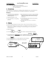
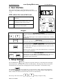
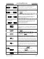
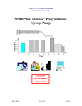
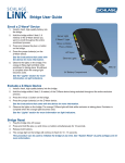
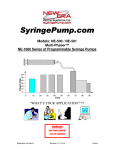
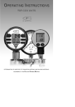
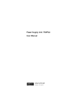
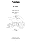
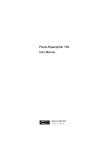
SyringeHeater.com SyringePump.com Syringe Heater Thermo-Kinetic Heat Clamping Model: HEATER-KIT-1LG HEATER-KIT-5SP WARNING CAUTION: CAUTION RISK OF ELECTRIC SHOCK Publication #800-01 NOT FOR CLINICAL USE ON HUMANS SURFACE OF HEATING PADS WILL GET VERY HOT Revision 4 V1.00 11/20/14 www.SyringeHeater.com New Era Pump Systems Inc. Model HEATER-KIT-1 1. General Information Thank you for purchasing the Syringe Heater Kit. Please familiarize yourself with the Syringe Heater’s operation by reading this user's manual. For future reference, record the serial number, located on the bottom identification label, and the date of purchase. New Era Pump Systems Inc., located in Farmingdale, NY USA, can be contacted at: Phone: (631) 249-1392 FAX: (707) 248-2089 Email: [email protected] www.SyringePump.com www.SyringeHeater.com This Operating Manual, and the Syringe Heater’s hardware, electronics, and firmware are copyrighted. Copyright 2012, all rights reserved. 1.1 Warnings ! ! ! ! ! ! ! ! ! and Cautions ! Read the user’s manual Risk of electrical shock. Do not cut heating pads. Surface of heating pads can get very hot No user serviceable parts are inside. Disconnect power from the heater when connecting or disconnecting cables. Do not immerse the heater control unit or pads in liquid Install on a stable surface. The heater can automatically start when the heater is operating or when attached to an external control device. ! ! ! ! ! Prevent liquids from entering openings. Only connect to a power source as specified on the power supply label. Do not push objects of any kind into openings, except for appropriate cables and connectors. If the heater becomes damaged, do not use unless certified safe by a qualified technician. Damage includes, but is not excluded to, frayed cords and deterioration in performance. Discharge static from control cables before connecting by touching the cable to ground. 1.2 Disclaimer New Era Pump Systems Inc. makes no representations or warranties, expressed, statutory or implied, regarding the fitness or merchantability of this product for any particular purpose. Further, New Era Pump Systems Inc. is not liable for any damages, including but not limited to, lost profits, lost savings, or other incidental or consequential damages arising from ownership or use of this product, or for any delay in the performance of its obligations under the warranty due to causes beyond its control. New Era Pump Systems Inc. also reserves the right to make any improvements or modifications to the product described in this manual at any time, without notice of these changes. New Era Pump Systems Inc. products are not designed, intended, or authorized for use in applications or as system components intended to support or sustain human life, as a clinical medical device for humans, or for any application in which the failure of the product could create a situation where personal injury or death may occur. All brand and product names used in this manual are the trademarks of their respective owners. 1.3 Warranty New Era Pump Systems Inc. warranties this product and accessories for a period of two years, parts and labor, from the date of purchase. The repaired unit will be covered for the period of the remainder of the original warranty or 90 days, whichever is greater. A return authorization number must be obtained from New Era Pump Systems Inc. before returning a unit for repair. Warranty covered repairs will not be performed without a return authorization number. At the option of New Era Pump Systems Inc., a defective unit will be either repaired or replaced. This warranty does not cover damage by any cause including, but not limited to, any malfunction, defect or failure caused by or resulting from unauthorized service or parts, improper maintenance, operation contrary to furnished instructions, shipping or transit accidents, modifications or repair by the user, harsh environments, misuse, neglect, abuse, accident, incorrect line voltage, fire, flood, other natural disasters, or normal wear and tear. Changes or modifications not approved by New Era Pump Systems Inc. could void the warranty. The foregoing is in lieu of all other expressed warranties and New Era Pump Systems Inc. does not assume or authorize any party to assume for it any other obligation or liability. Publication #1200-01 1 11/20/14 www.SyringeHeater.com New Era Pump Systems Inc. Model HEATER-KIT-1 1.4 Packing List Included with the Syringe Heater are the following items: • Primary heating pad with 2 releasable plastic ties. • Basic Operating Manual. 2. Overview The syringe heater controls the power to a heating pad with a temperature sensor. It is controlled from a microcontroller based system which monitors and regulates the temperature on the heating pad. Features: ♦ User adjustable Thermo-Kinetic Heat Clamping for precision regulation of Set Point temperature. ♦ RS-232 bi-directional control from a computer with builtin RS-232 network driver. RS-232 network supports up to 100 heaters, pumps and other devices from a single computer port. ♦ Maximum temperature of 185 C ♦ Power Failure Mode: Restarts the heater Active Mode after a power interruption. ♦ Non-volatile memory of all operating parameters. ♦ Selectable Temperature units of C or F (Celsius or Fahrenheit) 3. Setup ♦ Attach the primary heating pad to the larger connector (8 pin) on the end of the heater control box. ♦ Wrap the primary heating pad around the syringe body. Temperature will be measured near the point where the wires are attached to the heating pad. Secure the heating pad to the syringe with the 2 releasable plastic ties. ♦ Plug in the heater ♦ Use the Up and Down arrow buttons to adjust the temperature Set Point ENTER SETUP ♦ To start heating the pad, simultaneously press the 2 ACTIVE buttons, and STOP . The ACTIVE LED will be lit. The heater will begin to regulate the temperature on the pad. ♦ Press the ENTER STOP button to stop heat regulation and exit Active Mode. ♦ The temperature Set Point can be adjusted while in Active Mode. Temperature Sensor Primary Heating Pad 1LG Publication #1200-01 Secondary Heating Pad Connector Primary Heating Pad Connector 2 11/20/14 www.SyringeHeater.com New Era Pump Systems Inc. The controller will display, as the default display, the current temperature of the primary heating pad, in the currently selected units, C or F. PUMP LEDs indicate the status of the heater. COMPUTER 4. User Interface Model HEATER-KIT-1 ACTIVE Temperature Set Point is actively being maintained OUT Heating pads are being powered. Flashing indicates on/off power duty cycle to slow down heating when near the Set Point Heating pad temperature is greater than 20 degrees C above the Set Point SETUP ALARM ACTIVE ALARM ENTER STOP OUT ACTIVE Keypad SETUP ENTER STOP Up / Down Arrow Buttons Increases or decreases settings. By default, will change the temperature Set Point Settings with decimal points: Press both buttons simulaneously to shift the decimal point. SETUP Button Displays the setup menu. Each press will display the next menu selection. ENTER / STOP Button When displaying the setup menu or changing a value, will select the entry or save the new value. The display will blink when the new value is saved in non-volatile memory. Otherwise, will stop the heater. The Active LED will turn off. Temperature will no longer be maintained. ┌ ACTIVE ┐ SETUP ENTER STOP Active Mode Buttons Simultaneously press the SETUP and ENTER/STOP buttons. The Active LED will turn on and the heatings pads will start heating until the temperature reaches the Set Point. 5. Setup Settings SETUP Press the SETUP button to display the setup menu. Each press of the Setup button will display the next menu entry. All settings are saved in non-volatile memory. Pressing an Up or Down arrow button will immediately select Temperature Clamping Set Point and will increment or decrement the setting. ENTER Press ENTER STOP to select a menu entry or accept and enter a setting, exiting Setup Configuration. A value being changed will be automatically entered after a few seconds time out period. The display will blink to indicate the value has been entered and saved in non-volatile memory. Press an Up or Down arrow button Publication #1200-01 or 3 to change a displayed setting. 11/20/14 New Era Pump Systems Inc. www.SyringeHeater.com Model HEATER-KIT-1 The setup menu is as follows: Indicates that the display alternates between 2 displays. Temperature Clamp Set Point When active, the heater will heat the pads until the set point is reached on the primary pad. Use the Fiine Tune settings to control the regulation of the temperature clamping. Alarm Set Point will be 20 degrees C (36 F) above the Set Point. Fine Tune Temperature Set Point Fine Tunes thermo-kinetic settings to improve regulation of temperature Set Point clamping. Press Slow Down Temperature Delta ENTER STOP to display the Fine Tune settings sub-menu. Degrees below Set Point to begin heating slow down. Heating duty cycle will be reduced based on degrees below temperature set point and rate of temperature change. Set to 0 to disable. Default = 10. Set Point heat clamping duty cycle base percentage (Pc). Hold duty cycle percentage is the base heat duty cycle percentage to trickle charge the heaters to clamp the temperature setting. Actual percentage will be dynamically adjusted up or down according to temperature feedback Set to 0 to disable. Default = 10. This setting will not appear in Active Mode. C is default setting Set temperature units: C or F (Celsius or Farenheit). When the units are changed, all settings will change units without being converted. Enable Lock Out Mode. Set to 1 to enable. 0 is default setting. n Press ENTER STOP when enabled to set Lock Out code. Lock Out code: use arrow keys to set blinking digit. nnnn SETUP Press or ENTER STOP to move to next digit. Power failure mode. Set to 1 to enable. 0 is default setting. n When Power Failure Mode is enabled, if the heater loses power while in Active Mode, the heater will power up in Active Mode when power is restored. Alarm mode will override Active Mode. RS-232 communications network address. 0 is default setting. nn Sets the RS-232 network address for use with a network of heaters and pumps connected to a computer. 00 is the default address. This setting will not appear in Active Mode Reset all settings. First press ENTER STOP to select. ENTER Then set to ‘1’. Press STOP again to reset all settings to default settings. ‘0’ will exit reset without making any changes. Displays the firmware version. Publication #1200-01 4 11/20/14 www.SyringeHeater.com New Era Pump Systems Inc. Model HEATER-KIT-1 6. Operation The heater constantly monitors and displays the temperature measured on the primary heating pad. In Active Mode, the heater will apply power to the heating pads, as indicated by the OUT LED, until the Set Point temperature is measured on the heating pad. In Thermo-Kinetic mode, the OUT LED will pulse on and off, indicating a partial heating duty cycle. 6.1 Thermo-Kinetic Mode T e m p e r a t u r e Set Point Temperature Hold Heating Percentage Heat Loss Compensation Heat Clamping Slow Down Temperature Delta ThermoThermo-Kinetic Heat Clamping Setup settings “Slow Down Temperature Delta” and “Hold Percentage” configure Thermo-Kinetic Mode. The default settings are 10 degrees C Slow Down Delta and 10% power Hold Heating percentage. When Thermo-Kinetic Mode is off (settings set to 0), power to the heatings pads will remain on until the Set Point is reached. Then turn on again when the termperature reduces to below the Set Point. This will generaly cause large temperature swings. When power is turned off to the heating pads, the temperature will continue to rise for several seconds. Thermo-Kinetic Mode reduces the average power to the heating pads by dynamically reacting to changes in the temperature measurement and rate of change. Then, when the Set Point is reached, the average power applied to the heating pads will be reduced to a level that dynamically compensates for heat loss, clamping the temperature at the Set Point. The average power is set by controlling the on/off power duty cycle of the heating pads, as indicated by the pulse rate of the OUT LED. Slow Down Temperature Delta Set to the number of degrees below the Set Point to begin reducing the average power to the heating pads. Increasing this number will minimize over shooting the Set Point. The larger the number, the longer it will take to reach the Set Point. A good starting value is 10 degrees. The average power will be linearly reduced in proportion to the temperature delta below the Set Point. Then the power level will be adjusted based on the temperature change over time (temperature derivative). Hold Percentage The Hold Percentage provides just enough power to the heating pads to compenste for heat loss, clamping the temperature at the set point. The temperature hold heating percentage is used when the temperature is within +/- 1 degree of the Set Point temperature. The actual Hold Percentage is dynamically adjusted according to the measured temperature. When the temperature settles below the Set Point, the adjusted percentage is incremented. When the temperatrue settles above the Set Point, the adjusted percentage is decremented. These small changes in power will slowly nudge the temperature towards the Set Point, while minimizing over/under shooting. The Hold Percentage setting remains unaffected by the adjusted setting. The adjusted setting remains in affect until the heater control box is powered off. A good starting value is 10 Percent. Publication #1200-01 5 11/20/14 New Era Pump Systems Inc. www.SyringeHeater.com Model HEATER-KIT-1 6.2 Alarm Mode When the measured temperature reaches 20 C (36 F) above the Set Point, Alarm Mode is set. The heater exits Active Mode, turning the “Active” LED off, the red “Alarm” LED on, and the alarm message will flash. The message can be cleared by pressing any key after Alarm Mode is cleared. Alarm Mode is cleared, turning the “Alarm” LED off, when the measured temperature reduces to the set point, or the set point is raised. 6.3 Error Messages n Indicates a system fault, where ‘n’ is the fault code 1 Heater pad sensor differential 2 Control box internal temperature 3 Heater pad sensor minimum temperature 6.4 Calibration Heating pad calibration is performed through the RS-232 computer interface using the CAL command. Calibration is performed by measuring the primary heating pad temperature at 2 temperatures: One at room temperature, and one at a high set point of at least 25 C above room temperature. Measurements are in Celsius units. Notes on measuring the heating pad temperature: Measure the temperature on the inner part of the primary heating pad curve, under the temperature sensor. Only the primary heating pad, with a sensor, can be calibrated. 1) Power on the syringe heater. • Attach the computer cable (CBL-PC-PUMP-7) and start the terminal emulator PUMPTERM.EXE. • Verify communications is established with the heater by pressing the ENTER key on the PC. A response from the heater will indicate communications is established. 2) Measure the low point temperature. • Allow the temperature on the heating pad to reach room temperature for at least 1 minute. • Measure the temperature on the heating pad. • Very quickly, after reading the temperature, enter the low point temperature as a 1 to 3 digit Celsius number (spaces are optional) with the following command: CAL L nnn 3) Measure the high point temperature. • On the syringe heater, or from the PC, enter a temperature set point at least 25 degrees higher than the room temperature. To set from the PC, use the SET command. For example to set a 75 degree set point (assuming C units set), enter: SET 75 • Start the syringe heater by pressing the Active buttons, or from the PC, use the RUN command. • Wait for the heating pad to reach the set point. Then wait 1 minute for the temperature to settle and dissipate throughout the heating pad. • Measure the temperature on the heating pad • Very quickly, after reading the temperature, enter the high point temperature as a 1 to 3 digit Celsius number (spaces are optional) with the following command : CAL H nnn 4) Finalize the heating pad calibration. • The calibration entry process can be repeated before the process is finalized, or the entries can be ignored if the process is not finalized. Turning off power will discard the entries. • To finalize the calibration, enter the command: CAL Publication #1200-01 6 11/20/14 New Era Pump Systems Inc. www.SyringeHeater.com Model HEATER-KIT-1 • If the calibration data was valid, the heater will respond with: OK If there was an error in the calibration, the heater will respond with: ?NA After calibration, the heating pad number will be set to 0. Selecting pad number 1, will change the calibration back to the factory defaults: PAD 1 6.5 Lock Out Mode When enabled, Lock Out mode will lock out the keypad until the user defined lock out code is entered. If any key is pressed while locked out, the display will show: Pressing either arrow key will enter Lock Out code entry mode: to the previous display. nnnn . Any other button will return Use the arrow buttons to set the blinking digit. Press the Setup or Enter buttons to move to the next digit. If the code entered is wrong, the display will show: . Press any button to clear. If the code is correct, the keypad will be unlocked, but Lock Out setting will remain enabled. The next time power is turned on, the keypad will be locked out. Use Setup mode to disable Lock Out mode. RS-232 communications is not affected by Lock Out Mode. Also, Lock Out can be set remotely. 6.5.1 Setup SETUP Use the n , where ‘n’ indicates the current setting: button to select Lock Out Mode: ‘1’ enabled and ‘0’ disabled. Use the up and down buttons to select, then press ENTER STOP . If enabled, then the currrent Lock Out code is displayed and can be changed. To change the code, use the up SETUP and down buttons to change the blinking digit. Press ENTER STOP to move to next digit. After the last digit the new code is entered. or The keypad will be immediately locked out upon entering the Lock Out code. 6.5.2 Default Code Bypass If the lock out code is forgotten, the default code can be entered: While turning on power to the unit, press and hold the Setup key. Lock Out code entry mode will be displayed. To unlock the keypad, enter the code: 1392. Publication #1200-01 7 11/20/14 New Era Pump Systems Inc. www.SyringeHeater.com Model HEATER-KIT-1 7. RS-232 Communications The syringe heater can communicate with any computer or device with an RS-232 communications port or converter. 7.1 Connection and Networking On the side of the heater are 2 square RJ-11 (“phone jack” style) sockets. Connect the RS-232 cable (CBL-PC-PUMP-7) into the socket labeled “Computer”. Connect the other end to the serial port on the computer, or other control device. If the heater is part of a RS-232 network, connect a RS-232 network cable (CBL-NET-7) between the socket labeled “Pump” on the heater and the socket labeled “Computer” on the next device in the network. Repeat for each device in the network, connecting the “To Network” or “Pump” socket of one device to the “Computer” socket on the next device in the network. Up to 100 devices can be networked together with a computer. When communicating with a device in a multi-device network, each preceding device in the network must be powered on. Each device in the network needs a unique network address to identify the device to the computer. Network addresses are from 00 to 99. If the network consists of only 1 device, set the device’s address to 0. Also, each device needs to be set to the same baud rate as the computer. Use the ‘Setup’ function on the keypad to set the network address. See section 5, “Setup Settings”. The '*ADR' command can also be used to set the network address. The supported baud rate is 19200 7.2 RS-232 Protocol: When the device is used in a multi-device network configuration, precede each command with a device address. Devices will ignore all commands that do not have their defined network address. If the network address is not specified in the command, the address will default to 0. After a command is sent to the device, the device will not accept any further communications until the current command has been processed. Completion of the command processing is indicated when the first byte of the response packet is transmitted. While the user is changing data or configurations from the keypad, command processing is delayed. Communications to and from the device uses the following data frame: Supported RS-232 Data Frame Baud rate: 19,200 Frame: 10 bit data frame (8N1): Start bit: 1 Data bits: 8 Stop bits: 1 Parity: None Every command received by a device in the network is acknowledged by the device with a response packet that includes a status character indicating the current operational state of the device. 7.2.1 RS-232 General Syntax Legend The following syntax expansion legend is common to all syntax expansions: Except where indicated, all command and response characters are ASCII data. <float> => <f> [ <float> ] Floating point number. Maximum of 4 digits plus 1 decimal point. Maximum of 3 digits to the right of the decimal point. <on-off> => On, enabled Off, disabled 1 0 Publication #1200-01 8 11/20/14 New Era Pump Systems Inc. www.SyringeHeater.com <count data> => <n> [<n>] Valid values: 1 to 99 <number data> => <n> [<n>] Valid values: 0 to 99 Model HEATER-KIT-1 <text> => "any printable character" [<text>] <f> => { <n> | . } Floating point digits <n> => { 0 | 1 | 2 | 3 | 4 | 5 | 6 | 7 | 8 | 9 } Digits <byte> => “one byte of any data” () One byte of data expressed as (0xhh), where ‘hh’ is the data in hexadecimal. => Is defined by. Syntax expands to next level of expansion. <> Non-terminal syntax expansion [] Optional syntax {} Required syntax | Or. Choose one of the syntax options. λ None. Syntax expands to nothing (lambda production). "" Description of syntax expansion 7.2.2 RS-232 Protocol: Basic Mode Command syntax (to device): <basic command protocol> => <command data> <CR> Response syntax (from device): <basic response protocol> => <STX> <response data> <ETX> In the “Basic” communications mode, a master-slave protocol is used, whereby the device will only transmit in response to a received command. When the device receives the <basic command protocol>, <command data> will automatically be stripped of all space and control characters, and all text will be converted to upper case. This simplifies communications with the device when commands are being manually typed in from a generic terminal emulator. 7.2.3 RS-232 Protocol: Basic Mode Common Syntax <transmitted data> => { <command data> | <response data> } <command data> => [<address> | * ] [<command>] <response data> => <address> <status> [ <data> ] <status> => { <prompt> | <alarm> } <prompt> => S Heater Stopped H Heater Active A Heater Alarm To device From device Operational state of device <alarm> => A ? <alarm type> Alarm <alarm type> => R E O H F Heater power was reset (power was interrupted) Error Out of range High temperature alarm Sensor Fault <address> => <n> [ <n> ] * <data> => <text> Device network address, 0 to 99 System command (overrides network address) Response to command Publication #1200-01 9 11/20/14 New Era Pump Systems Inc. www.SyringeHeater.com <CR> => (0x0D) <STX> => (0x02) <ETX> => (0x03) <length> => <byte> Model HEATER-KIT-1 Carriage return Start of packet transmission indicator End of packet transmission indicator Number of bytes remaining in packet, including this byte 7.3 Command Errors and Alarms If a command received by the device is not recognized or the data is invalid, an error message will be in the <data> field of the response packet following the <prompt> field. The following are the error responses: <command error> => ? <error> <error> => λ NA OOR COM IGN Command is not recognized (‘?’ only) Command is not currently applicable Command data is out of range Invalid communications packet received Command ignored due to a simultaneous new Phase start When an alarm occurs, the alarm must be acknowledged before any data is changed or the device is started. Alarms are acknowledged by the user clearing the alarm message on the keypad, or the alarm status being sent in response to any valid RS-232 command. 7.4 RS-232 Command Set Data changes made from RS-232 will not be stored in non-volatile memory until a Save command is executed: SAV A packet without a command is interpreted as a status query. The addressed device responds with a status only response packet. Except where noted, a setting command without its parameter queries the command setting. The response packet data will include the requested data. In general, the query response data will be in the same format as the parameter for setting the command. For example, the query temperature setpoint command ‘SET’ will respond with ‘<nnn>‘ as the response ‘<data>‘. Otherwise, the command is a set command. If the data was set, a status only response packet will be sent. If the data was not set, the response packet will include an error (<command error>) message indicating why the data was not set. All commands are upper case. Spaces are optional. Lower case letters are converted to uppercase when received. 7.5 RS-232 Commands <command> => HEATING COMMANDS START ACTIVE HEATING MODE RUN Enter active mode, maintaining heating temperature. STOP ACTIVE HEATING MODE STP Exit active mode. Stops heating the heating pads. TEMPERATURE QUERY TMP Query primary heating pad temperature in currently set units. Query response: <nnn> HEATING SET POINT SET [ <nnn> ] Publication #1200-01 Set/Query Heating set point in currently set units. Query response: <nnn> 10 11/20/14 New Era Pump Systems Inc. www.SyringeHeater.com Model HEATER-KIT-1 TEMPERATURE FINE TUNE SLOW DOWN DELTA FTS [ <nnn> ] Set/Query Fine Tune Slow down degree setting. Query response: <nnn> TEMPERATURE FINE TUNE HOLD PERCENTAGE FTH [ <nnn> ] Set/Query Fine Tune temperature hold percentage. Query response: {nnn} CALIBRATION CAL [< L | H > [<nnn>] ] Heating pad calibration. See calibration section for details. HEATING PAD SELECTION PAD [ n ] Heating pad calibration setting. 1 – Default. 0 – Calibrated. Query response: <n> TEMPERATURE UNITS UNT [ C | F ] Set/Query temperature units Query response: {C | F} GENERAL SETUP COMMANDS SAVE NEW SETTINGS SAV Save all new settings in non-volatile memory POWER FAILURE MODE PF [ 0 | 1 ] Set/Query Power Failure mode Query response: {0 | 1} LOCK OUT MODE LOC [ < 0 | 1 [<nnnn>] > Set/Query Lock Out mode Query response: {0 | 1 <nnnn>} NETWORK ADDRESS ADR [ <nn> ] Set/Query RS-232 network address Query response: <nn> FIRMWARE VERSION VER Query firmware version. Query response: NE800V<n>.<nn> SYSTEM RESET RESET Publication #1200-01 Reset all parameters to factory defaults 11 11/20/14 New Era Pump Systems Inc. www.SyringeHeater.com Model HEATER-KIT-1 8. Accessories 8.1 Additional Heating Pads Only the primary heating pad has a temperature sensor. Additional heating pads do not have temperature sensors. The heating pads will heat when the primary heating pad heats. Each heating pad must be the same type and size as the primary heating pad. The following are part numbers for ordering additional heating pads: Type Base Model Large SYRINGEHEATER-1LG SYRINGEHEATER-5SP Small Replacement Primary Pad HEATERPAD1-1LG HEATERPAD1-5SP Second Heating Pad HEATERPAD2-1LG HEATERPAD2-5SP Third and Additional Heating Pads HEATER-PAD3-1LG HEATER-PAD3-5SP 8.2 RS-232 Network Cables RS-232 Network Primary Cable 7 foot cable Part #: CBL-PC-PUMP-7 25 foot cable Part #: CBL-PC-PUMP-25 USB to RS-232 Converter Cable USB to RS-232 cable Part #: CBL-USB232 Cable to connect the first device of an RS-232 network to a standard PC’s serial port with a DB-9 connector. Attaches to the RS-232 Network Primary Cable to allow communication through a PC’s USB port. Includes a CD with software drivers. RS-232 Network Secondary Cable 7 foot cable Part #: CBL-NET-7 25 foot cable Part #: CBL-NET-25 Cable to connect additional devices, after the first, to an RS-232 network. 9. Specifications Power requirements Power consumption Maximum temperature setting Selectable temperature units 120 VAC 60Hz, North American style plug 0.33 A (One heating pad) 185 C (365 F) C (Celsius) or F (Fahrenheit) Heating pad: HEATER-PADx-1LG Pad size (PAD1-1LG) L 9 cm x W 7.5 cm (3.5” x 3.0”) Cord length 5.4 cm (21”) Heating pad: HEATER-PADx-5SP Pad size (PAD1-5SP) Heating area: L 50 cm x W 1.5 cm (20.0” x 0.625”) Overall length: L 740 mm x W 15 mm (29.13” x 0.59”) Cord length 90 cm (36”) Controller case dimensions L 4.625” x W 2.5” x H 1.5” (11.7475 cm x 6.35 cm x 3.81 cm) RS-232 network protocol RS-232 network address range Baud rate: 19,200 Data Frame: 8N1 00 to 99 (100 devices maximum) Publication #1200-01 12 11/20/14