1
Notes for the Software Hut.
Mike Holcombe
Contents
CONTENTS
Chapter 1.
Essentials
1. Software engineering in teams.
2. Setting up a team.
3. Finding and keeping a client.
4. The organisational framework.
5. Planning.
6. Dealing with problems.
7. Risk analysis.
8. Review.
Chapter 2.
Starting a project
1. Project beginnings.
2. The first meetings with the client.
3. Initial stages of building a requirements document.
4. Techniques for requirements elicitation.
5. Putting your knowledge together.
6. Specifying and measuring the quality attributes of the system.
7. The formal requirements document.
8. Review.
Chapter 3
Simple models - preparing for testing
1. Simple models.
2. The requirements document.
3. Estimating resources.
4. Review.
Chapter 4.
Designing the system tests
1. Preparing to build the functional test sets.
2. The functional testing strategy.
3. The full system test process.
4.Test documentation.
5. Design for test.
6. Non-functional testing
7. Testing internet applications and web sites.
8. Review.
Chapter 5
Documenting the system.
1. What is documentation for and who is going to use it?
2. Coding standards and documents for programmers.
3. Coding standards for Java.
4. Maintenance documentation.
5. User manuals.
Page 1
Contents
6. Version control.
7. Summary.
Appendix A. QuizMaster Requirements document.
Appendix B.
A Software Cost Estimation for the QuizMaster
Appendix C . QuizMaster System: Students’ User Manual - Stand alone Edition
Bibliography
Page 2
Chapter 1. Essentials
Chapter 1
Essentials.
Summary: Group work and software projects. How to set up a team. Carrying out a skills audit.
Choosing a way of working. Finding and keeping a client. Day to day activities. Keeping an archive. Some basics of planning. Dealing with problems. When things go wrong. Risk analysis.
1. Software engineering in teams.
Almost all software that is produced commercially is developed with teams of people. The
teams might be structured into programmers, testers, requirements engineers etc. It probably has
some hierarchical arrangement with managers, team leaders, sub teams and so on. The team
could be a small one, perhaps 2 or 3 people or it could involve hundreds. The team may all be
working in the same place or it could be scattered over different locations, countries, even. What
is common to all these manifestations is that they share a general objective, the production or
development of some software product.
Learning how to work effectively in a team is thus a vital part of one’s education as a software
engineer. Many universities and colleges provide some place in the curriculum where a team
project is set up and you have to participate with colleagues in a design project. In many of these
activities the professor or instructor will set some problem and you try to solve it, learning along
the way from the many experiences you share, good and not so good, which relate to the way
your team worked.
There are many sources of advice about how to make the most of a team but there are no easy
rules or procedures. A team comprises of a group of distinctive and independent personalities,
we cannot generalise very easily about how these personalities will interact and how the team
will progress. However, there are some simple basic rules which seem to work and the purpose
of this short chapter is to describe these.
2. Setting up a team.
This may not be an issue since your instructor may allocate you to a team without providing any
choice in the matter. This is a reasonable reflection of what happens in industry so one can’t
really complain. However, if that is not the case and you are asked to form yourselves into teams
here are some pointers to doing that.
Suppose that we are trying to form a team of 4 or 5. We need to look for a blend of personalities
and skills that will knit together and produce an effective force. The nature of the project may
determine some of the parameters but let us assume that all the potential candidates for the team
are reasonably well prepared in terms of having progressed satisfactorily through the programming, design, and more specialised courses needed for the project.
The key requirement is for the team to be people who get along reasonably well with each other,
who can meet in suitable places and who all have a similar interest in doing well in the project
- partly because of the desire to get a good grade in the exercise.
Page 30
Chapter 1. Essentials
A software project involves a number of key activities and it is important that there are members
of the team who can make useful contributions to these activities. We need some good programmers but there are many other things to be done in the project, we need people who have abilities
to organise, to plan, to negotiate and communicate - with, for example, the client - and there is
always the need to document clearly and systematically various important things.
No single person will come to the project with all these abilities to a high level but most people
will be capable of most to some extent. We emphasise the equal involvement of all team members in all the important activities and so the project will be a framework within which all team
members will develop significant skills across the board. You will learn both technical material
and skills as well as how to co-operate, communicate, organise, resolve problems, deliver a successful product and mature as a software professional in a way that is just not possible in other
types of learning.
In situations where there is an odd number of team members it makes pair programming awkward to organise. It doesn’t really work with three people round a machine so the best way to
operate if you have a team of 5 is to have two pairs doing programming, testing and debugging
and the other person can do a variety of tasks such as reviewing code, documents and models,
system testing, preparing documentation and manuals, etc. The important thing is to keep
changing the pairs around, involve everyone equally in contributing to the project and to keep
talking to each other.
Doing a real project with a real business client will change you forever, your perspective on
life, on your colleagues and on the process of working together. Your understanding of the profession of a software engineer will be transformed, as will your job prospects, since future interviewers will be really impressed by your experiences in doing real software development, it
will set you apart from the rest of the applicants as someone with extra skills and experiences
and value for their business.
A skills audit is an important feature of any team building exercise. It may only happen in an
informal way, you gradually learn what your colleagues know and can do. It is best, initially,
however, to try to write down what your strengths and weaknesses are and to share this with the
rest of the potential team. See if there are people with a good selection of the skills needed. If
most of your team are good at programming but not very good at talking to people or organising
documentation then that should be a cue to try to recruit someone with these skills. The deal is
then that the Software Hut approach will help them to develop those skills that they are weak
in. Programming is all about multi-skilling and learning all the key skills needed in software development to a high level.
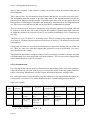
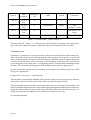
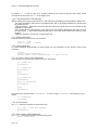
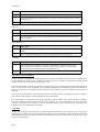
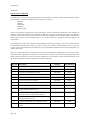
Itemise your groups relevant skills - or at least your own assessment of them in a table like the
following :
skill
Page 31
excellent
Programming in Java
pete, jing
Programming in PHP
jane
Communications skills
oscar, ahmed
moderate
ahmed, oscar
limited
jane
oscar
jing, jane
pete
Chapter 1. Essentials
skill
excellent
moderate
limited
Organisational skills
jing
ahmed, oscar
pete, jane
Documenting skills
jane, oscar
ahmed, jing
pete
...
Table 1.
This is only a rough guide and the definition of the skills and levels is bound to be vague but it
does give you some basis to plan out your project and also a simple benchmark to compare with
at the end of the project. One would hope that there is a significant improvement across the
board by the end of the course.
3. Finding and keeping a client.
It may be the case that your instructor has found a suitable client with a realistic problem for
you to tackle. Ideally the client should not be in your academic department but from outside,
either from an external business or other organisation or perhaps from another department within the University. It may be more realistic for your instructor to organise a collection of projects
which involve a member of the staff of the department acting as a client. Much can be learned
from this experience but a real client provides that unpredictability that we should be able to
handle.
If you have to find your own client, and this is perfectly possible, then there are a number of
avenues worth exploring.
Check out your family and friends. It is likely that you know someone who has a small business
or who works for a local organisation. See if they would like some high quality software developed exclusively for them at a nominal cost.
Contact the local Chamber of Commerce or similar business organisation.
Approach local charities, these often have interesting and useful problems and cannot always
afford to get professional software created for them.
Talk to staff in other parts of the University, this is always a rich source of good projects, in my
experience.
Examples of systems that could be useful include:
databases for customers, orders, and other relevant information;
web pages with some useful functionality, perhaps allowing customers to request products,
catalogues, or to supply information such as customer details, market surveys etc.;
Page 32
Chapter 1. Essentials
planning tools which might enable an organisation to organise its resources better, time tabling some of its activities in a more effective way;
there are many other applications that you could consider.
Once you have identified a potential client it is important to establish the following:
is the client prepared to give enough of their time to meet you and identify what it is they
require in detail as well as to evaluate your software over the period of the project?
As we shall see later, good software engineering requires a very close interaction with the client,
if the client cannot afford the time required, say a couple of hours a week for a semester, then
look for another client. If the client does not operate locally this could also be a problem.
Having identified a client and a potential problem see your instructor to find out if they think it
is appropriate for your capabilities. Your instructor may have originally intended you to do a
team project that they had made up. Argue the case that it would be much better for you if you
could do a real project instead. It would also be much better for your client. Even if you are not
totally successful in building a complete solution your client would have learnt a lot about their
own business or organisation simply because your questions would have made them think about
what they do in a fresh light. It may be possible for an incomplete system to be completed by
some of the team during the vacation. Everyone will benefit, even your instructor. It is so much
better if your efforts are directed at building something that will be useful to someone rather
than something that, once it has been marked, will be thrown away!
You will also learn so much about dealing with a client, about delivering a quality solution and
about planning and organising yourselves because you will be better motivated compared with
the traditional sort of projects that professors dream up. You cannot learn many of these things
from lectures or books, you must learn by doing it all for real.
Once you have a client and a project it is vital that you make efforts to keep them both. Regular
feedback to the client is essential, so regular meetings must be held. When you attend these
meetings make sure that you approach them in a professional way. Think smart and look smart.
Give your client confidence that his/her investment will be worth while and they will get something out of the exercise. Never break appointments, if some other crisis occurs it is vital that
the client is warned if it is necessary to change a planned meeting.
Always describe what you have achieved since the last meeting. Always appear interested in the
client’s business, and express some confidence about how the project is going but do not exaggerate progress. Honesty will ultimately pay.
My experience has been that clients really enjoy the activity, many have never been a client for
a software development project before and they are getting some useful insights that may be
valuable in later years. They also generally like working with bright and enthusiastic young
people. So for them it will be both an enjoyable and a productive experience. It should be the
same for you.
4. The organisational framework.
Page 33
Chapter 1. Essentials
We will now assume that you have been allocated to a team or have organised one yourself. We
now describe a few simple, and perhaps obvious, things to do. Do not underestimate these factors, many projects fail because of the simplest and most stupid of mistakes and omissions.
Learn as much about your team members as possible, their names, addresses, phone numbers,
e-mail addresses and so on. It is vital that you can contact everyone easily because you will be
working on the project in a variety of locations, not just the usual laboratories. This is something
that is different to most industrial practice where the team occupies the same premises all day
and every day. See if everyone will sign up to a working agreement that identifies the responsibilities and expectations of all the team members.
Agree on the location for the first meeting and make sure everyone turns up on time. This is
important if one wants to be treated professionally, as your client will want to do, if you do not
behave in a professional way why should anyone treat you like a professional? This is the first
test, if a team member does not make it to an important and agreed meeting and they do not have
a excellent reason, then this is a major threat to the project and to all of the team’s grades. The
team agreement should emphasise the obligation on all team members to attend all meetings. If
the culprit does not listen to reason then complain to the instructor.
Teams can work well in a variety of ways. Sometimes it is worth agreeing on having a team
leader who takes over the responsibilities of organising and chairing meetings, of leading the
planning and other key co-ordinating activities. If everyone is happy with this solution then this
can work. My recommendation, however, is for the role to be shared, each member of the team
taking over the running of the team for, say, two weeks at a time. Thus everyone gets an opportunity to develop their leadership skills and to take responsibility for the team’s progress.
It is important to establish an effective method of working. First of all you will need to hold
planning and progress meetings. Depending on the time scale and your other activities there
might be several of these each week. The current project leader should chair the session. There
should be another team member to act as secretary - this could be the person who will take over
as project leader after the current one. The meetings should be minuted formally. This requires
the following information about the meeting to be recorded:
Date;
Location;
Attendance;
Absences (with reason);
and then the record of the meeting.
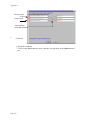
See Figure 1 for an example of a template that works.
Each item of discussion should be numbered and a brief description of the item made. Any conclusions and decisions taken must be recorded together with any further actions agreed. These
must describe:
what is to be done;
who is to do it and
when it must be done by.
Page 34
Chapter 1. Essentials
All this is absolutely vital if the project is not to suffer from confusion and recriminations.
Each team should appoint an archivist. This role can also be shared around the team. The key
requirement is that someone is given the responsibility to maintain a complete and accurate
record of the plans and meetings of the project. This person should set up a suitable filestore on
some server where all the team has access so that anyone can consult the archive to see what the
status and history of the project is. We will later discuss the archiving of other, more technical
documents, requirements documents, test cases, code, etc. The regime for these documents is
different, however.
Another important activity is the recording of the amount of time each team member spends per
week on the project activities. This should be recorded on a weekly time sheet for the team. Examples will be found in a later chapter.
It is vital that we record accurately the time we spend on projects.
Firstly it enables us to track our individual performance and helps us to identify where we are
making progress and where we may still have improvements to make as we undertake various
types of activity in the software development process. This is vital for apprentice software engineering and, in fact, should be something that we do throughout our professional lives. The
Personal Software Process [Humph1996] provides an excellent framework for this.
Secondly it will help us to collect data from which we can predict how much effort future activities might take. Estimating the resources - time, people etc. - needed for the development of
software is notoriously difficult. Many decisions are made in an ad hoc manner and usually lead
to disaster or, at best, to a very inefficient and expensive process. We have to learn to do better.
As we will see, later, planning is important.
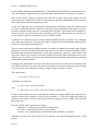
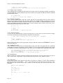
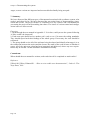
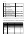
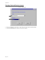
Minutes of group meetings.
Group no. …………….
Date of meeting [dd/mm]……………….Time of meeting [hh:mm]………... Place of meeting…………….
Present………………………………………………………………………………………………………….
Absent (reason)………………………………………………………………………………………………...
Agenda item
1
2
3
Page 35
Details:
Action by:
Deadline
:
Chapter 1. Essentials
4
5
6
Figure 1. A template for the minutes of a meeting.
Finally, a tip about your personal approach to being a professional. If you meet any serious engineer or scientist you will notice that they always carry with them a day book. These days, this
doesn’t have to be a book, a palm computer might also be used. The purpose of the day book is
to record, events, thoughts and other useful things as you experience them. You would record
things during meetings and while reading books and papers and build up an archive of useful
facts and ideas. Maybe it could also contain a list of things that you want to do, also very useful
since it is easy to forget.
5. Planning.
The basics of planning include:
decomposing the overall task into a collection of smaller tasks;
identifying the dependencies and relationships between these tasks;
estimating the amount of resource (time and manpower) required to complete the tasks;
setting delivery times for each task;
describing the plan in some suitable notation, eg.a GANTT chart.
Plans will inevitably require review and alteration since the estimates made of the time needed
to complete tasks is often wrong, further understanding of the project could lead to a different
structure to the previous task decomposition as well as exceptional circumstances, such as illness, intervening. The regular meetings provide an opportunity to review and re plan the project.
Do not shy away from hard decisions in these meetings. It is very easy to pretend that everything
is all right when it isn’t. Equally one can get depressed about progress.
We now look at some planning techniques. There is software that is widely available for project
planning, however, this is often much more complex than is needed here.
It is necessary to split each phase down into activities at a level where these can be assigned to
individual team pairs, or possibly, a larger group of team members. It is then necessary to monitor how progress is made with each of these activities, and to do this one needs a schedule
describing which activities are to be undertaken when. Some activities will be pre-requisites
for others, in the sense that one activity will depend on the output of a previous one.
5.1. PERT (Programme Evaluation and Review Technique).
This is a technique that enables a schedule to be constructed that meets all the constraints of
the pre-requisites and identifies the critical path through the programme. The critical path is,
the part of the schedule which determines the minimum time in which the whole project can be
Page 36
Chapter 1. Essentials
completed. It allows us to identify the activities which are most important in terms of their
effect on the overall timing of the programme, and hence to identify those which need to be
monitored most carefully.
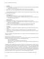
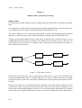
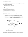
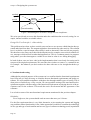
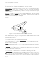
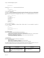
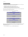
The basis of PERT is a graphical representation of the activities known as a PERT chart. This
diagram consists of nodes to represent activities, which is annotated both with the name of the
activity and with its duration (in whatever time units are being used: typically days, weeks or
months). Where one activity is a direct pre-requisite for another there is a directed arc from the
earlier to the later node. There are also two special nodes, one for the start of the programme
and one for its finish. A typical example of such a graph is given in Figure 2, which follows
from the description of PERT in Boehm, [Boehm1981].
test +
technology
research
10
code1
20
planning
meeting1
5
start
story
cards1
10
client
meeting1
5
test+
integrate,
test,
deliver
20
code2
20
Figure 2. An PERT chart for a simple project.
In this chart (Figure 2) we have taken a rather simplistic view of the process. There is likely to
be a lot more iteration and the chart will be much more extensive in most cases. The numbers
refer to person-hours of work and are just crude estimates. we would expect the activities to be
much shorter in a full time project. This plan tries to take into account the fact that most student team members will have to attend other classes and activities outside of the project. This
needs to be taken account of sensibly.
In constructing a PERT chart it is often easier to start at the finish and work backwards rather
than start at the start and work forwards, this way we can try to ensure that all the prerequisites
for a node are identified and added to the chart. Even so, it is common that such a chart may
need to change as the project develops and additional nodes are identified or different activities
are found to be necessary.
In traditional approaches, once the chart has been constructed it is used to determine the critical path, that is the path for the project which will take the longest time.Here the situation is
much more dynamic and fluid and the role of the chart is merely to identify potential problems.
In the example above, there is a potential issue in that the team carrying out the technology
research might hold the rest up at the planning meeting. It might thus be sensible to involve
more people in this aspect, but not loosing site of the problem that too many people working in
an uncoordinated way is not only inefficient but it is also a cause of potential team rows if
some members feel that they have been wasting their time carrying out work that is not very
useful to the project or has been duplicated by others.
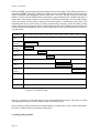
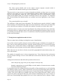
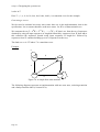
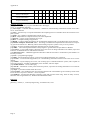
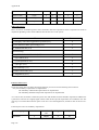
5.2. Gantt Charts
Page 37
Chapter 1. Essentials
While the PERT chart displays the relationships between the timing of the different activities, a
complicated PERT chart can be difficult to read in terms of deciding which activities will actually be scheduled when during the periods when they can occur. For this reason it is sometime
useful to derive from the PERT chart an alternative representation of the schedule known as a
Gantt chart. This simply consists of a column for each time period and a row for each activity,
with a line drawn on the chart to indicate when that activity is scheduled to take place. The
beginning and end of each activity is usually marked with a triangle, and if the chart is being
used to monitor actual progress then it is conventional to fill in the triangles as the activities are
actually started and completed. One possible Gantt chart for the project illustrated in Figure 2
is given below.
Week
1
2
3
4
5
6
7
8
9
10
11
12
start
technology
research
client
meeting_1
planning
meeting_1
story
cards_1
test+
code_1
test+
code_2
integrate,
test+
deliver
Figure 3. A GANTT chart.
There are a number of tools that help to create and maintain these charts. They may be worth
investigating but many are more complex than we usually require.
Now we have to make an allocation of team members, usually pairs, to the various tasks identified. This could be done by annotation of the chart.
6. Dealing with problems.
Page 38
Chapter 1. Essentials
It is inevitable that things will go wrong from time to time. It is the teams that are able to deal
with problems effectively that turn out to be successful. It is not about how clever people in the
team are but the culture within the team. If this culture is one of co-operation, discussion, building consensus and treating each member as an intelligent individual with a legitimate point of
view then resolutions can be found. If people are stubborn, arrogant, dismissive and unco-operative then it is much harder. Try not to loose one’s temper, be patient and considerate to others,
discuss the issues on the basis of an informed knowledge of the matters under discussion rather
than based on prejudice and guesswork. Seek expert advice if the argument is about a technical
point, the benefits of different strategies or approaches. Talk to the client as well. All these
things can be sorted out if everyone is positive and prepared to give and take. software engineering is all about co-operation, communication and treating people with respect and trust. All
problems are soluble somehow.
If you really hit a crisis and there seems no way out seek arbitration. Find someone that everyone in the team respects, perhaps a tutor or professor, and explain the issues to them and ask
them to make a judgement. This might be a simple compromise that everyone was too uptight
to see or it might be a ruling in favour of one side or another.
Try not to be upset if your argument is not the one that is successful in this process. Think about
what has happened and see how you might benefit from the experience. Perhaps the way you
handled your argument or yourself was counter-productive. Successful people in life reflect on
their experiences and learn from them, adapting their future behaviour in order to ensure future
success.
Sometimes you get into an argument where nobody is prepared to give way. This can happen if
you are just working as a pair or it might occur with more people in the team involved. A simple
suggestion from [Miller2002] might be useful. He discusses the issue in terms of pair programming but the technique can be extended to bigger groups.
First, every person involved has to ensure that they understand the conflicting opinions.
Then each person is asked to rank his/her opinion on a scale of 1 to 3 with 1 meaning “I don’t
really care” to 3 meaning “I’ll quit if I don’t get my way”. So 2 could be “I am interested in this
argument and I am prepared to spend some time looking into it, I want to hear your point of view
but I will take some convincing that it is better than mine”.
If there is a highest ranked option then that is what is pursued until evidence emerges that it
might not be the best.
If there is a tie then you can pick a direction at random if the scores are low. If both views are
ranked at 2 then it needs more time to research and analyse the issue. A trick here might be for
each individual to try to make the best case they can for the opposing view. If that doesn’t lead
to a preferred option then either ask a third party or spend a little time taking forward both ideas
until a clearer position and, hopefully, a consensus emerges.
Failing all of this then seek advice from the project supervisor.
Sometimes differences are not as real as they seem and are mainly due to poor communication
and a lack of understanding of what each other mean. These problems should resolve themselves if you try to listen carefully to what the others are saying, perhaps even writing it all
down, this act often forces you to be a little more precise than before and can be the key to clarity
on both sides.
Page 39
Chapter 1. Essentials
7. Risk analysis.
Projects can always go wrong. One way to minimise the impact of this is to carry out a risk
analysis. This involves an identification of the hazards (things that can go wrong), and their
associated risks (estimates of the probability of those hazards occurring, and the likely severity
of the consequences).
There are many hazards including:
technical hazards - using the wrong technology (one that cannot be used to solve the
problem) or one that the team is insufficiently experienced with;
planning hazards - the software being developed is too complex for the resources available and the project plans are far too ambitious;
personnel hazards - some of the team members are not capable of delivering, perhaps
they are lazy and poorly motivated or perhaps their technical knowledge is weak.
client hazards - the client is too busy or lacks interest in the project, the client is trying
to exploit the team by demanding too much for too little.
These hazards relate to the project and its overall management. There are other hazards in the
form of delivering an unacceptable final product. We try to deal with this by encouraging close
client contact. Even this may still fail to prevent problems. Many failures are due to the nonfunctional attributes not being met, [Gilb1988].
In order to prevent problems with the non-functional or quality attributes it is important that
these are identified clearly and precisely and means for testing for compliance developed. This
will be a concern of a later Chapter. We need to be able to estimate the likely range of variation
in these attributes, and realise that the risks to the success of a project come essentially from
the possibility of actual attribute values finishing up outside the specified range. Thus, the risk
to a project must be controlled and we need to find solutions which will meet at least the minimum required levels for all the critical attributes.
Part of this risk control process therefore involves identifying which attributes pose the greatest
risk to the project, and this comes in two forms. Some attributes will be mandatory and others
merely desirable. Clearly we need to focus on the former for most of the time. These critical
attributes have to monitored.
8. Review.
This chapter has tried to provide some practical guidance about how to organise your project
team. Most of it is just common sense but it is surprising how often these simple practices get
forgotten in the heat of the moment. By forcing yourselves to act professionally, to document
and plan your approach you should avoid many of the common pitfalls that so bedevil software
development projects.
Don’t assume that, because you have been made aware of potential pitfalls and ways to avoid
them that everything will be plain sailing. There will be problems, some of these will be down
to poor organisation, not planning the project properly and delivering what is needed at a time
and to a satisfactory level of quality. However some problems may be beyond your control. Perhaps the client hasn’t given you the correct information or hasn’t reviewed your ideas quickly
enough. Perhaps team members have been ill. There is not much you can do about the latter except try to adapt the project be reorganising the plans and team activities.mSometimes, however, problems arise because of personal differences and lack of interest or commitment amongst
the team. There is no easy solution to this, discussion on the basis of a friendly meeting, perhaps
held away from the lab, might be useful. Building a pleasant social atmosphere in the group can
Page 40
Chapter 1. Essentials
be helpful. One senior developer, who is often called in to rescue problem projects in his company said: “Projects must party”, meaning that spending some time relaxing together, perhaps
over a meal or a drink, or some other outing, pays large dividends in terms of morale. many
problems in software engineering are human and social ones and should not be ignored.
Exercises.
1. Meet with your team members and agree on a mode of working where and when will you meet,
decide on individual responsibilities e.g. who is responsible for archiving the documentation, chairing meetings maintaining the project plan etc.
2. Read one or more articles on project management - these are readily available. Research into
the question - why do software projects fail? Identify some of the possible pitfalls that your
project might suffer from, what are you going to do to avoid these?
3. Develop PERT or Gaunt charts for the project, to cover at least the first few weeks.
4. Carry out some risk analysis - how can you control and minimise these risks?
Conundrum.
Your project involves programming in a language which is familiar to only one member of your
team. Two others have a slight knowledge of the language but have never written anything serious in it. You are trying to do pair programming but the ‘expert’ is getting frustrated because
whenever she is paired with another team member progress is very slow (because much of the
time is taken up with explanations of what she things is obvious}. She feels that it would be better if she worked on her own on the program and the other team members did other things, such
as writing documentation and testing.
How should you deal with the situation?
For a discussion of this see Chapter 11.
References.
[Boehm1981]. B. Boehm, “Software engineering economics”, Prentice-Hall, 1981.
[Gilb1988]. T. Gilb, Principles of software engineering management, edited by Susannah Finzi.
- Wokingham : Addison-Wesley, 1988.
[Humph1996.]. W. S. Humphrey, “A Discipline for Software Engineering”, Addison-Wesley,
1996.
Page 41
Chapter 2.
Starting an XP project
Chapter 2
Starting a project
Summary: Meeting the client or customer. The first attempt at defining the scope of the project.
Some techniques for requirements elicitation. Basic business analysis. Functional and nonfunctional requirements. Identifying dependencies and constraints. The structure of a traditional
requirements document. An example of a real requirements document from a project.
1. Project beginnings.
It is the first class for the project and you have now got a client and a project. Initially, it all
seems very daunting and many students are pessimistic about being able to build something that
looks very complicated with a technology or method that is unfamiliar. You will almost certainly succeed if the precautions that I have indicated in earlier chapters are taken.1 If there is a failure in a team it is because of individual failures or a breakdown in communication it is rarely
due to the teams being technically or intellectually unable to cope. It does depend, of course, on
the project scope being appropriate, neither too hard or too easy and this requires some judgement and experience on the part of the tutor.
We will assume that you are starting with a requirements which includes a reasonably simple
initial phase and you should confirm with your client and/or tutor whether there is a part of the
system which is clearly within your capabilities and which can be addressed first in order to gain
confidence. In fact, the approach of building things in stages and getting them to work properly
will soon build up your confidence.
The initial project description may be nothing more than a paragraph and it might seem to be
too vague to allow you to start. Remember, however, that this description is just a starting point
to you exploring, with the client, the client’s business, its needs and possible solutions and so
there will be a lot of preliminary work to do to define the scope of the project and what a potential solution might look like.
This is not an easy stage of any project and it is impossible to learn exactly how to do it in books
and lectures, there is no substitute for trying it out and reflecting, as you go, on how the process
proceeds.
We will look at the initial descriptions of two real projects that were done by students in 2001
and see how one of them progressed to a complete solution.
Project 1. Quizmaster.
Background.
The brief was given to design a questionnaire-generating programme for an organisation that provides training
for lawyers. Its main purpose is to allow trainees to answer weekly exercises for specific topics using a computer
as an aid. This is in contrast to the approach used previously where exercises are handed out on paper, the student
answers the questions and this is marked manually.
Project description: The proposed system should automate this task by removing the need for the lecturer to do
any marking or for the students to mark their own work. The student instead answers the exercise on the computer
and a mark is returned immediately. The system also monitors certain statistics on the student’s performance on
1. If it is any consolation I have run such projects for a dozen years or so and it always seems to work out.
Page 41
Chapter 2.
Starting an XP project
these tests so that lecturers can see how individual students are progressing and if they have been doing the exercises that they should have been doing. The system is for use on the Legal Practice Centre course that typically
has 120 students for the duration of a one year long course consisting of two semesters. Each student takes four
compulsory topics during Semester One and three chosen topics during the second semester. The chosen topics
for the second semester are not known at the start of the year.
The system must allow for different topics and for topics to be changed, so it has to be possible to add and remove
topics. Also, since the students on the course will change it will also be necessary for the system to add and
remove students, especially at the end of the course when all students will need to be removed. The system must
maintain details of topics and their exercises, students and the topics they take and the required statistics for how
students have performed on certain topics. This information will change often so it must be easy to change any of
the information stored by the system.
Project 2. WASTETEC.
Background.
The client develops solutions for waste problems facing small and medium sized businesses in and around South
Yorkshire. They act as a broker between two companies, one with unwanted waste and another requiring waste.
The client does not charge for their service; they are part-financed by the European Community Regional Development Fund.
Current manual procedures: If a customer has waste to sell, he/she contacts the client and provides the necessary
details. The client then adds this to the existing database. If another company wants to buy some waste, they
approach the client with their requirements, and the client searches the database for any matches. If there is a
match found, the client puts the two companies in contact with each other.
Project description: The client requires a WWW based search, enabling potential customers wanting to buy waste
to get direct access to the relevant details of the database, without contacting the client, and releasing any company details. The client also requires the system to enable potential customers with waste to sell, to advertise their
waste. If a customer finds a match for his/her requirements, they should then be able to make enquiries to the client, on-line. The client then follows this up separately, and is no longer a concern of the system.
As mentioned before these were actual projects carried out by 2nd year computer science and
software engineering students at the University of Sheffield during the 2nd semester of 2000/
2001.1 We will follow the development of the Quizmaster project and the appendices contain
more detailed information about the system that was built for this client.
2. The first meetings with the client.
This might be a session involving all of the teams working on that client’s problem and generally involves the client giving a presentation about their business and what they are trying to
achieve, their objectives for the system. There will usually be an opportunity to ask general
questions relating to the system but these should not be technical computing questions - apart
from general things such as the sort of network available or to be purchased for the solution.
Remember that the client may know very little about Computer Science or programming, that’s
why they have come to you, you are the experts. Their expertise is in their business.
If you are not sharing your client with other teams then the first meeting will be a more informal
one. It is important to prepare for it.
Starting with the initial project description there are a number of things you should do:
Research into your client’s business:
have they got a web page?
1.
Page 42
Chapter 2.
Starting an XP project
can you find any other published information about their business?
what do they sell - products or services or what?
what sort of clients do they typically have?
who are their competitors, what can you find out about them?
Preparing carefully for the first meeting will impress the client that you are professionals and
will give them the confidence to proceed, don’t forget that they are giving up some of their time
and this is a cost to their business.
Turn up looking smart, on time and at the right place. Do not chew gum or do any other things
that would distract the client into doubting whether your are worth working with. These first
impressions are important, you may think that they are trivial or superficial issues but it is part
of the business expectation that the clients will have. In later life you will have to recognise
these things, anyway, so it might as well be now!
3. Initial stages of building a requirements document.
Although we will be using stories as the basis for the software development it is important to
have a clearly structured list of requirements, both functional and non-functional, so that an
overall description of the complete target system is available.
This is developed in discussions with the client. At a suitable point we will develop a system
metaphor and extract stories from this requirements and start developing the system.
There are a number of reasons why a requirements document may be important. Your client will
often want something that can be shown to his/her superiors in order to provide some indication
of what is being developed. Naturally, this document may change during the course of the
project. It will be built around the stories together with the non-functional requirements and other contextual information. We have already commented on how some businesses will require
such formal statements in order to approve things like project expenditure. The key thing is to
be aware that it will change and to make sure that it is used as a summary of what the current
knowledge of the proposed system is.
The process of carrying out a full requirements analysis in a traditional software engineering
context is often done at the start of the project and only occasionally revisited in any fundamental way later. We emphasise, here the construction of an initial one. It will contain, not only the
functional requirements but also details of important quality attributes of the system.
Requirements analysis and specification is deceptively difficult since many clients don't know
what they really want and they don't know what it costs or how long it will take to deliver. They
often fail to recognise how hard it is to create a reliable system and how long it takes. Some
might expect it to be done by next week!
Clients express problems naturally in their own words, words that might be unfamiliar to us or
used in different ways, don't assume that your understanding of a particular word or term is the
same as theirs. We need to identify what the terminology means and to agree on it. The construction of a glossary of business and technical terms should be an outcome of this dialogue.
Page 43
Chapter 2.
Starting an XP project
When talking to clients realise that there may be hidden factors at stake: political, historical,
geographical. You may need to understand these features of a business organisation in order to
understand the reasons for particular requirements. Remember that there are probably more personnel involved in the business, who may have different requirements and different priorities,
it is an important but delicate task to ascertain these.
The initial software requirements analysis can be divided into a number of activities:
Problem recognition;
Evaluation and synthesis;
Modelling and metaphor building;
Specification of user stories;
Review and discussion.
In the first week or two of the project, you should be evaluating and synthesising the problem
and requirements information from the client. Always write down your thoughts, refer to these
at your formal group meetings and put a date on them. Later, you may need to revisit some issue
when you have forgotten the details. Although we wish to keep the paperwork to a minimum
records of this stage should be saved, carefully.
You should already be modelling aspects of the client's business processes, in an attempt to clarify and make more specific your understanding of these processes. We will suggest a suitable
way to help collect your thoughts together in the next Chapter.
By the next week, you should be refining some of your models so that they can be incorporated
into the requirements document.
Problem evaluation involves:
defining all external observable relevant business objects;
evaluating the flow and content of relevant information in the business;
defining and elaborating all relevant software functions;
understanding relevant business behaviour (events);
understanding user behaviour (tasks);
establishing systems interface characteristics;
uncovering additional constraints.
All of these activities are difficult.
4. Techniques for requirements elicitation.
There are a number of useful approaches that can be used to elicit user requirements and to gain
user involvement. Here are 6 approaches that can be useful:
Interviews;
Structured questionnaires;
Observation - again only successful, if you can do it unobtrusively;
Concurrent protocols - where a user describes his/her tasks whilst performing them;
Card sorting - useful if you want to understand the user's classification of his/her knowledge domain;
Page 44
Chapter 2.
Starting an XP project
Carrying out a user role yourself;
Interviews have to be prepared carefully. In the first meeting, when you know little about the
problem, then it is important to ask the client to describe all the key aspects of the system, try
to guide them away from the desire to get to intricate detail about what they want when you simply do not understand what they are talking about. As you get immersed in their business context it is important to manage the meetings carefully. Identify what you want to know
beforehand and prepare a set of questions that will help you to find out what you need. Once
these questions are answered then you can explore further areas. It will often be the case that a
question will stimulate the client into telling you some other piece of information, carefully
record this. It is best to go to the meeting with all the team but make sure that there is a principal
speaker and someone to record what is said. There is nothing more off putting for a client than
to be faced with people asking questions from all angles on all sorts of disconnected topics. Plan
your meeting carefully and try to stick to it. The same advice applies to any other stakeholder
you meet, such as a user of the proposed system.
If you are not able to meet the client or the user then leaving a structured written questionnaire
is another technique. Try to group related questions together. Also try to make your questions
clear, unambiguous and relevant. Leave a contact number or email in case the person filling in
the form has a query. Make sure that people know where to send the finished questionnaire and
try to impress upon them, with tact, of course, that you need it by a specific date if the project
is not to be held up.
Sometimes it is possible to visit the client and observe the business in action. Here you may be
able to observe users in their current work. This is helpful in providing you with a context and
a better idea of what the users are like, what they expect or are comfortable with and what sort
of system you might be trying to emulate. Pay particular attention to the sort of user interfaces
that seem popular. Take care not to disrupt their work too much. Some users are happy to talk
their way through their tasks while you are there.
If you can watch the user explain a process while they are doing it then this can be very useful
since you can ask questions about what they are doing and why. It may be possible to ask whether another way of doing things would be possible.
Writing down processes on cards and then putting these together in sequences of actions may
also help. The mere process of writing down what you think is going on is useful and your understanding can then be confirmed or corrected by the users.
Finally, perhaps you would be allowed to try out the current system - paper-based or computerised - yourself. This can be very illuminating.
5. Putting your knowledge together.
Gathering all this information is one thing but putting it all together into a coherent model of the
business is quite another. There are no simple solutions to this problem. Common sense is the
best approach!
Defining all external observable relevant business objects.
We need to look at the sorts of things that are coherent entities in the part of the business we are
considering. These could include: products, contracts, orders, invoices and such like. Make a
Page 45
Chapter 2.
Starting an XP project
proper list of them and try to distinguish between those that are involved with the external activities of the business, for example objects that are apparent to the customers, agents and suppliers of the business, and to those involved in the monitoring of the company such as taxation
and other government authorities and the objects that are defined for the convenience of the internal management of the company, these might be: internal orders, memos and planning material, records and archives of company activity etc.
Evaluating the flow and content of relevant information in the business.
Each business process will involve a number of individual processes which take place in an organised way. What is the order in which this information is processed, what type of information
is it? Try to get a general picture of what happens and when during typical scenarios of business
activity. You will refer to the business objects described above, if you come across one that has
not been identified, previously, then it needs to be added to the list. Equally, if you found an
object that doesn’t seem to feature in any process that you are analysing, eliminate it. It may be
that you find some difficulty in modelling things at the right level, there is always the temptation
to try to describe things in too much detail. Try to avoid this at this stage. We are looking for a
rather “broad brush” description of what is going on.
Defining and elaborating all relevant software functions.
Now we can start imagining what our software is going to do. It might be replacing some existing function, either a manual operation or in some obsolete software, or it might be a new feature
that has not been implemented with software before. We will come back to this process in Chapter 6, at the moment it suffices to write it down as clearly and concisely as possible.
Understanding relevant business behaviour (events).
Now we have to try to figure out how these things actually relate to each other. We should try
to define some common scenarios which explain the overall operation of the business processes
through the medium of identifying the events that cause the scenario to operate. These could be
the placing of an order by a customer, here we might need to identify what sort of customer is
involved, a new or existing one, trade or retail. The business process involved for each of these
may be different and so the system will be expected to behave differently as well. This leads to
us identifying the different conditions that must apply for the different cases. Again we need to
check that our business objects and processes described above are consistent with this.
Understanding user behaviour with task analysis.
There are many techniques for task analysis which can be used to elicit user requirements relatively easily. Task analysis tends to concentrate on the way users conduct business processes
now. It may include user actions which do not involve interaction with a computer. Nevertheless, a task analysis model can form a useful representation for discussion with your users, helping to identify aspects of the task with which users are comfortable and familiar with and which
could be incorporated into the structure of interaction with the required system. Alternatively,
it can help identify aspects of the task which are currently problematic and could be improved
in the required system.
As if requirements capture and analysis were not sufficiently complicated, we must often obtain
the views of different users, who are likely to have different stakes in the outcome of the new
system. Hence, you may need to identify and resolve stakeholder views. You should ask yourselves, who are your users? They are not necessarily a single, homogeneous group of people
with the same tasks, the same goals or the same view of the world who are the clients?
Page 46
Chapter 2.
Starting an XP project
In Checkland's Soft Systems Methodology, [Checkland1990] a distinction is made between clients, who usually commission the system and stand to benefit from its outcomes, and actors.
Who are the actors? Actors are system users, who have to play a part in the system, but who
may not directly benefit from it. How are you going to gain these stakeholders' involvement in
and commitment to the development process?
At the end of this process you should have identified the dependencies that the solution needs
to relate to within the business context as well as any basic assumptions that pertain. You may
also have started to think about the constraints that will affect your solution, the available resources you have at your disposal, time, technology and so on. This needs to be clarified, it is
no use trying to specify a system that you are not able to build.
A collection of requirements notes can be produced which can help to organise ones’ thoughts
into a more structured form. The aim is to produce a detailed list of requirements which provides
a basis for early planning and approval.
The functional requirements should be stated, eventually, in a tabular form using simple English
statements. These will be derived from the user stories as we will see in the next chapter. In fact,
the functional requirements document is really just a summary of the story cards as they exist
at the time. Where it is necessary to break a complex functional requirement down into a set of
simpler ones, do so but try to preserve the connection between related requirements by grouping
and numbering them together.
Looking at the Quizmaster system it is clear that one actor or user is the lecturer and they wish
to be able to set tests. Now a test will consist of a number of questions and so the task of setting
a test will involve the subtasks of setting a single question a number of times.
The requirement:
n. the lecturer can set a test
could then be restated as:
n.1 the lecturer can set a question
and
n.2 the lecturer can create a test from a number of questions.
If some of the requirements are poorly defined or subject to change identify them and put some
measure on their risk of change, even if it is just a number 1...5 (low risk...high risk) which you
allocate on the basis of your best guess given the knowledge you have available. We will find
this useful, later.
We also classify each requirement as being:
mandatory - it must be present in the final solution;
desirable - it should be present if at all possible;
optional - only implemented if all others are done and there is still time.
Naturally the client will specify these levels and they may change during the course of the
project.
Page 47
Chapter 2.
Starting an XP project
We will use user story cards as the main mechanism for determining detailed functional requirements.
6. Specifying and measuring the quality attributes of the system.
We talk about two main types of requirements: functional and non-functional. Put simply the
functional requirement describes what the system has to do and the non-functional describes
how well it is supposed to do it. This is a little simplistic but it will do for a start.
We often put most emphasis on the functional requirements and neglect the non-functional or
assume that they are easily dealt with. In fact, identifying the non-functional requirements can
be difficult. We need to define them carefully and what is more we need to set some sort of acceptability levels for them and a means of demonstrating compliance with these levels. It is possible to refine the notion of non-functional requirements into two categories: quality attributes,
which determine how well the system should perform and resource attributes, which constrain
or limit the possible solutions to your business problem. Unless these are addressed a system
may not be successful, even if all the functional requirements are met.
For most software systems some of these attributes will be critical, that is, unless each of those
attributes achieves some required level then the system will probably not be successful, no
matter how well it may meet its functional requirements or meet the goals for its other
attributes. Thus it is essential to identify all the attributes, and to identify which ones are critical, and then to ensure that they are all met.
Identifying Attributes
The International Standards Organisation provides a taxonomy of quality attributes in its draft
standard1 for software systems, (ISO 9126). [ISO 9126]. As you read through the following list,
based on that standard, make a note of those attributes which you feel could be critical to your
project. The list is not exhaustive: you may see other classifications of qualities elsewhere and
you may identify critical qualities for your system that do not appear here. Some of the issues
that are discussed here may not be relevant to your own project. Think about them and focus on
those that seem to be the most critical. Discuss this with your client. The ISO 9120 standard is
concerned with the quality of the product. There is another standard, ISO9001, which deals with
the engineering process.
Functionality:
Suitability - the presence of an appropriate set of functions for specified tasks
Accuracy - the presence of correct and predictable results from specified input
Interoperability - the ability to interact with other specified systems
Compliance - the adherence to specified standards, laws and regulations
Security - the ability to prevent unauthorised access to programs and data
Reliability:
Maturity - the frequency of faults/ rate of software failure
Fault tolerance - the continuity of software execution in the presence of faults
Recoverability - the ease with which performance and data can be recovered in the case of
system failure
1.
Page 48
Chapter 2.
Starting an XP project
Usability:
Understandability - the effort required by users to recognise application concepts and their
applicability to user tasks
Learnability - the ease with which an application's functions can be learned
Operability - the effort required by users to operate and control the application
From the ISO 9241 standard for usability in software and hardware design a number of other
issues are identified such as:
System efficiency:
Time behaviour - the adequacy of system response and performance times
Resource behaviour - the acceptability of amount (and duration) of resources consumed in
performing system functions
Maintainability:
Analysability - the ability to identify and diagnose deficiencies in the system
Changeability - the ability to modify the system, to add new functions, remove faults or
adapt to environmental change
Stability - the risk of unexpected effects arising from modifications to the system
Testability - the ease with which correct system functioning can be verified
Portability:
Adaptability - the opportunity afforded to adapt the system to different specified environments
Installability - the effort required to install the software in a specified environment
Replaceability - the effort required to use the software in place of other software in a specified environment
This list of attributes is much larger than you will require. Select the most appropriate and concentrate on these.
Specifying the acceptable level of an attribute.
Having identified critical quality attributes, you need to specify what level or measure of each
attribute is acceptable in your system.You should identify at least:
the worst acceptable level
the planned level - be ambitious, but remain realistic!
the best level - just to provide a marker for what might be technically possible but infeasible for you.
It might be useful to identify the present level (if there is an existing system to evaluate). These
levels should be specified and measurable in quantitative terms or metrics. It is not good enough
to specify that your system will be "very" efficient, “easy to use” or "extremely" adaptable. You
must attempt to define operational, measurable criteria against which your system can be
judged. This will lead on to defining a set of tests that will establish whether the attribute has
been delivered to the required level. We will look at testing in a later chapter but it will often be
important to identify, at least in general terms, what the testing approach will be.
For example, if one of your usability criteria for your system is its suitability for the task,
Page 49
Chapter 2.
Starting an XP project
a measure of its effectiveness is the percentage of user goals achieved in a given time;
a measure of its efficiency is the time for a type of user to complete a set of tasks;
A series of experiments (tests) could be organised in which users are asked to carry out some
important tasks using the system, we would then be measuring how well these were carried out,
how long it took, how many mistakes were made etc. These experiments should be repeated
with as many people as possible in order to get a useful result. Alternatively, a measure of satisfaction, for example, can be gained on a rating scale, e.g. a scale of 1-5 by using suitable questionnaires distributed to a selection of users during a trial period of evaluation. If access to real
users is not possible in the timescale you could use some of your friends, preferably those with
a similar knowledge of computing as the intended users of the system.
For each numbered attribute we will specify a quality level and eventually a test for determining whether it is met in the final, delivered, software.
User characteristics and user interface characteristics
It is worth writing down a description of who the intended users of the systems are expected to
be.
Some of the basic principles behind your design of the user interface should also be documented. This does not mean that you should design some specific interface options but some simple
diagrams can help the client to visualise how the system might look.
7. The formal requirements document.
You must include the following information on any document you produce:
document type - e.g. requirements document
author(s)
version
date
The main body of the requirements document should have the following components:
Introduction and background;
Elementary business model;
User characteristics;
Functional requirements;
Non-functional requirements;
Dependencies and assumptions;
Constraints;
User interface characteristics;
Plan - a schedule of work with milestones, meetings and deliverables.
Glossary of terms (with an index)
The requirements will change as we progress. We will therefore regard the requirements document produced during this phase as an initial one which will change as the project unfurls but
it is important that the client, as well as the team, have some idea where they are going.
Page 50
Chapter 2.
Starting an XP project
The document should have clearly defined sections and paragraphs, referenced by number and
listed on a contents page. This is vitally important for future cross-referencing between other
system deliverables and the requirements specification. As Tom Gilb makes clear, thorough
cross-checking is necessary for software reliability. It is also vital when we come to testing that
each requirement has a suitable test or set of tests associated with it. This then demonstrates that
we have met that particular requirement.
In the future, you will only be able to determine whether your designs, your test plan and test
cases and your coding are complete and correct, by reference to the sections of your requirements document.
You should discuss with the client whether they could sign off the document as a gesture of
good faith. It should be made clear, however, that the requirements are not totally fixed. Tell
them that major changes, without good business reasons, will threaten the project. Some changes will be feasible, some not and it is important to remember that there will be a fixed time limit
to the project. It’s better to have a good basic and useful system than an incomplete and useless
one.
8. Review.
We have concentrated on the discussions with the client and the formulation of the requirements
for the project, both functional and non-functional. It is important that you maintain good communications with the client so that he or she knows what you are thinking about. Later, when
we get down to more detail we will need to regularly review progress with the client, establishing the right language and concepts to use is vital. We have considered the structure of a fairly
formal requirements document, one which might form the basis of an agreement with the client
about what you hope to deliver.
Exercise.
Read the requirements document in Appendix A. Criticise it, in particular:
Are all the terms clear?
Are the functional requirements consistent, unambiguous, repetitive at the right level of
detail?
Are the non-functional requirements clearly defined, do they have suitable acceptance
levels and procedures identified?
How would you deal with any significant change in the requirements introduced by the
client?
Would it be easy to maintain?
Conundrum.
Your team is in trouble. The client has not been in touch with her feedback on the proposed system. She doesn’t have much experience of IT and only has a rather vague idea of what she
wants. There are no similar systems known to you that you can show her. You need to start getting some requirements identified and some initial stories prepared.
Do you:
a) wait until she has thought further about the system she wants?
Page 51
Chapter 2.
Starting an XP project
or
b) build a simple prototype using your imagination and background research in order to show
her something that might stimulate her ideas?
References.
[Checkland1990]. P. Checkland and J. Scholes, “Soft systems methodology in action”, Wiley,
1990.
[Gilb1988]. T. Gilb, Principles of software engineering management, edited by Susannah Finzi.
- Wokingham : Addison-Wesley, 1988.
[ISO 9126]
Page 52
Chapter 3. Simple models.
Chapter 3
Simple models - preparing for testing
Simple models.
It is impossible to define stringent test sets without knowing some details of what the system has
to do.
Our approach is to apply an extremely powerful modelling paradigm that seems to be fairly easy
to use and has proven excellence in the construction of functional test sets.
The task of taking the list of functional requirements or stories and identifying and organising
them into a coherent system can be achieved using the technique that we will describe next.
To gain a greater understanding of how all the stories fit together into a coherent system we need
to think about how they relate to each other. For example, it may be that one story can only occur
after another one has occurred, or it might be that at some point in the business cycle there is a
choice between several stories.
story 1
story 2
story 0
story 3
story 4
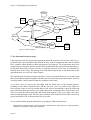
Figure 1. Collections of stories.
In this picture the initial story, story 0 is followed by either story 1 or story 2 (but not both at the
same time) and then either story 1 is followed by story 2 or story 3 is followed by story 4. It might
be then, that stories 2 and 4 are succeeded by further stories or the system returns back to the initial story.
In many cases each story is associated with a user interface screen, there may be a whole screen to
a given story or there may be many stories that can be driven from that screen. Although it is too
early to plan out the detailed graphics of the screen it is still important to identify the key elements
of the screen, the components that can be used by the user to instigate the process defined by a
Page 1
Chapter 3. Simple models.
story, the extra information needed to be displayed for this and the result of the operation of the
story displayed suitably.
It is sometimes a good idea to show the client some of your thoughts, on paper, of how the story
relates to your interface ideas. This can then lead to a clearer understanding of what is required.
The system will respond to some external stimuli, these will be, for example, users interacting with
a screen entering data, choosing options through mouse clicks, ticking boxes etc.; messages from
some other system, perhaps the results of a query to a database,
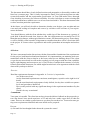
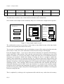
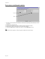
A SIMPLE EXAMPLE
Suppose that we are building a simple customer and orders database. We might identify a number
of stories such as the following:
1. Customer details are entered customer by customer.
2. Customer details can be edited.
3. Orders are entered by customer
4. Orders can be edited when necessary.
The details of the structure of the customer and orders details are left until later, we try to build an
abstract model of the user interface and then refine it. The test approach permits us to generate an
abstract high level test strategy and to refine the test cases in parallel with the refinement of the
system as explained in a later section [Holcombe1998], thus saving enormously in test case size
for large examples - a recent case study, involving 3 million transitions, demonstrated this.
Now we try to identify from these stories, what is prompting change (inputs), what internal
knowledge is needed (memory), what is the observable result (output) and how the memory
changes after the event. We also try to identify the risk that the story will be changed during the
course of the project as a means of trying to manage its evolution.
story
function
1
click(customer)
customer button
click
-
new customer
screen
-
low
1
enter(customer)
customer details
entered
current customer
database
confirmation
details screen
-
medium (nature of
details liable to
change)
1
confirm(custom
er)
customer confirm
button clicked
(current customer
database)
OK message and
start screen button
updated customer
database
low
3
click(order)
orders button
clicked
-
new orders screen
-
low
3
enter(order)
new order details
entered
current orders
database
confirmation orders
screen
-
high (nature of
details of orders
liable to change)
Page 2
input
current memory
output
updated memory
change risk
Chapter 3. Simple models.
3
confirm(order)
orders confirm
button clicked
3
quit()
click on return to
start button
(current orders
database)
Ok message and
start screen button
updated orders
database
low
-
start screen
-
low
Table 1. Requirements table (part)
The table above describes some of the functions from the stories in this form.
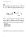
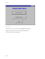
Now consider some simple screens which may help us to visualise how it might work in practice.
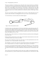
XProductsCo
CUSTOMERS
Customer details
Order details
Customer ref
Name
Ref.
Address
Order ref
Order details
ORDERS
Phone
Fax
email
Delivery
OK? Y
EXIT
N
QUIT
start screen
customers screen
Invoice ref
QUIT
OK? Y
N
orders screen
Figure 2. Some simple sample screens.
The confirmation screens are not shown. Notice that we have filled in some of the data details
which are not explicitly described in the stories.
The next task is to think about the order in which these screens will be deployed and the tasks that
can be done on each screen. This information will be described using a state diagram.
From the diagram (Figure 3) one can see how the basic functions are organised. We build up a
simple model like a state machine. Each state has associated with it an appropriate screen with
buttons, text fields etc. Of course, the model is simple and crude, there is no distinction between
entering a new customer’s details and editing an existing one but it is enough to explain the
method. These refinements are, what they say they are, refinements that can be dealt with later and
the work we do on test set generation here is built on them. The complete state machine is actually
called an X-machine, a term first introduced in 1974 and the basis ofmour simple approach to
modelling systems. These machines differ from the standard finite state machine and from the
statecharts sometimes used in UML in the sense that there is a memory in the machine and the
transitions involve functions that manipulate the memory as and when an input is received. This
provides an integrated, simple and practical modelling approach which combines in one diagram
both processing and data.
This is explained by referring to the requirements table and the story cards where the memory
Page 3
Chapter 3. Simple models.
connection is described.
For example, the memory in this case is likely to be the database that contains the record of
customers and orders.
The function click(customer) simply navigates between two screens and has no memory
implications, but the function enter(customer) will involve some interaction with the database, it
might search to see if the supposed new customer is in fact new before proceeding - generating a
message if the customer is already on the database. This can be described by the abort(customer)
function which has been developed as a result of thinking about the way the system fits together.
The function confirm(customer) actually changes the database by updating the records with the
information relating to the new customer.
The memory structure now needs to be discussed. Essentially we need to think about this in terms
of what basic types of memory structure is relevant at the different levels. At the top level, for
example we could represent it as a small vector or array of compound types of the form:
customer_details × order_details
filling in the actual details later. It may be, for example, that these will represent part of a
structured database with a set of special fields which relate to the design of the screens associated
with these operations. So customer_details would involve name, address etc. which would be
represented as some lower level compound data structure, perhaps and there would be basic
functions which insert values into the database table after testing for validity etc.
)
quit(customer
abor t(c
customers
)
stomer
click(cu
start
r)
click(customer)
custo
quit(order)
choice2
r)
ustome
confirm
customer
quit(
click(order)
ustome
enter(c
choice1
quit(order)
r)
ome
mer)
ust
rm(c
fi
n
o
c
rder)
o
click(
click(order)
orders
abor t(o
rder)
ente
r(ord
er)
confirm(order
)
Figure 3 X-machine diagram
confirm
order
Looking at Figure 3 there are a few other things to note. We have created a specific user interface
architecture which will constrain the solution in particular ways. For example it is not possible to
Page 4
Chapter 3. Simple models.
quit the process of inserting the order details during this process. We can abort after completing it,
however. This returns us to the orders state, then we can quit this screen.
The diagram can be used to define when and under what conditions different processes and stories
are available.
2. The requirements document.
The format of the requirements document that we will be presenting to our client was discussed in
the previous chapter and an example is given in Appendix A. The important thing about this
document is that it should be understandable to the client. It is built from the basic information in
the stories together with some outline ideas of the how the system might look and work. Important
non-functional requirements need to be specified and clear statements about how these are to be
interpreted and tested included. It is no good saying that the system will be fast if we don’t say
what that means, for example, in a Web based system this might include the maximum acceptable
page download times under suitable conditions, etc.
Although we have presented the requirements document and the story cards as two separate things
they are very closely related. There will be an interplay between them. We might regard the
requirements document as a summary of our current understanding of the overall system whereas
the stories are a more detailed description of individual aspects of its functionality with enough
information to allow us to plan, test and implement each story. The requirements document will
have extra and vital information about the proposed system, context statements, assumptions as
well as global quality attributes and non-functional requirements. It is these that we turn to next.
Non-Functional Requirements
A non-functional requirement either describes how well the system should perform (a quality
attribute) or a constraint or limit that the system must adhere to (a resource attribute). The nonfunctional requirements were defined in Chapter 4, and can be split into categories like reliability,
usability, efficiency, maintainability and portability etc. Here we give some example statements
that might be part of the requirements document.
Reliability:
Examples are:
For a single user, the system should crash no more than once per 10 hours.
The system should produce the correct values for any mathematical expression 100% of the
time.
If the system crashes, it should behave perfectly normally when loaded up again with minimal
data loss.
Usability:
Page 5
Chapter 3. Simple models.
A user should be able to add a new customer to the system within 1 minute.
A user should be able to add a new order to the system within 1 minute.
A user should be able to edit a customer’s details within 5 minutes (will vary with details
type).
A user should be able to produce reports and statistics within 1 minute.
Efficiency:
The system should load up within 15 seconds.
The time taken for the system to retrieve data from the server should never exceed 30 seconds.
Maintainability:
The system should be designed in such a way that makes it easy to be modified in the future.
The system should be designed in such a way that makes it easy to be tested.
Portability:
The client system should work on the client’s current computer network which is connected to
the Internet and has Windows 95 or better.
The system should be easy to install.
These statements need to be refined into a more precise statement in order to make them testable.
What, for example, does easy to install mean? we will look at this in the next Chapter.
From each story that we have discussed with the client we extract the key functional details. These
are grouped in sections with other story lines that are clearly related.
These requirements are categorized on the basis of which are mandatory, desirable and optional.
To do this we need to have an estimate of the time we might take to complete these and this will
help us to make these decisions. The next section looks at the process of trying to estimate this.
Naturally we must consult the client on which he/she thinks are mandatory etc. We have to be
realistic, however, you must not promise to do more than you can achieve in the time given.
3. Estimating resources.
If we have a model like the one above we can use something like the function point and object point
method. Here we try to estimate the amount of effort required to build a story or a screen with its
accompanying functionality.
To do this we look at each story and consider the functions contained in it. We then try to categorise
what sort of function this is. we can find information which estimates the amount of effort each
category of function might require, this data is being collected in industrial organisations and some
of it is published. We include some examples here. It is a good practice to try to measure your own
efforts for these functions to see if they agree with the estimates and to inform future projects.
Software cost estimation.
Page 6
Chapter 3. Simple models.
Basic questions at the start of the project and also at suitable review points during the project:
How long will it take?
What resources will it need?
How expensive will it be?
The approach is to use the techniques of Software measurement.
During the course of projects we measure the following parameters:
lines of code (loc) produced over the timescale;
number of observed defects over the timescale;
number of person hours worked over the timescale;
amount of time spent on debugging over the timescale;
amount of time spent on requirements over the timescale;
amount of time spent on design/specification/analysis over the timescale;
amount of time spent on writing documentation over the timescale;
amount of time spent on testing/review over the timescale;
etc.
These are all measures of production volume, product quality and effort. If we have some previous
experience and data of this type for old projects we may be able to estimate the effort and time
needed for the new project.
From the timesheets and documentation produced we should be able to find the following for the
completed project:
lines of code (loc) per person-month (pm);
cost per 1000 lines of code (kloc);
errors per kloc;
defects per kloc;
pages of documentation per kloc;
cost per page of documentation;
number of requirements;
average kloc per requirement.
If we have this data then we might be able to estimate what the next project will need in terms of
people and time.
But different types of project will require different amounts of effort, so we need to collect information about the type of project:
product functionality;
product quality;
product complexity;
product reliability requirements;
etc.
These are not always easy to measure, unlike the first set of measures.
Page 7
Chapter 3. Simple models.
We need to describe the software being built on the basis of the requirements in order to estimate
the resources needed. There are several techniques, none of which are very precise. If the new
project is very similar to the previous ones things are much simpler. If it is a completely new type
of project, perhaps involving a new technology, then it is much more difficult.
We will look at the function point method (see the Function Point User Group - www.ifpug.org).
There is also a more modern method called object point analysis.
Function point analysis (FPA) was developed by Albrecht in 1979, [Albrecht1979] for business information systems development.
The principle underlying FPA is that the effort required to construct a software system is a function
of the size and complexity of the product. The size is determined by the number and complexity of
the requirements not the size of the code.
Method.
1) for each requirement/story we decide if it is one of: input, output, inquiry, reference file, database.
2) assign a weight to each requirement: simple, average, complex.
3) consider other influencing factors: reusability, adaptability and weigh them according to a suitable scale. This is, to an extent, guesswork but if we have an idea of which requirements are hard
to implement and which are easier it will help us to plan.
Below are a list of influencing factors that could either make the requirements easier to implement
or harder to implement depending on how much influence these factors have on the system. Each
factor is allocated a number range and we try to estimate from this the likely weight of the factor.
criteria
simple
average
complex
number of different data elements
1-5
6-19
>10
input validation
formal
formal, logic
formal, logic, database
ease of use
low
average
high
Table 4: Input data (keyboard, screen, from other applications)
This means that if there are 4 data elements on a form and there is little data validation and ease of
use is not an issue then the input data requirement is simple. If there had to be some logic based
data validation then it would be average and if ease of use was a big issue then it would be complex
criteria
simple
average
complex
number of columns
1-6
7-15
>15
number of different data elements
1-5
6-10
>10
Page 8
Chapter 3. Simple models.
criteria
simple
number of formatted data elements
average
none
complex
some
many
Table 5: Output data (monitor, printer, to other application)
criteria
simple
average
complex
number of different keys
1
2
>2
ease of use
low
average
high
Table 6: Inquiries (search and display)
criteria
simple
average
complex
tables: number of different data elements
1-5
6-10
>10
tables: dimension
1
2
3
read-only files: number of different data elements
1-5
6-10
>10
read-only files: number of keys/sentence formats
1
2
>2
Table 7: Reference file (tables and read-only data
criteria
simple
average
complex
number of keys/sentence formats
1
2
>2
number of different data elements
1-20
21-40
>40
database already exists?
yes
-
no
new implementation?
no
yes
-
Table 8 : Databases (managed by the application)
Influencing factors.
Having identified the key functionality of the requirements we need to factor in the effects of a
variety of important aspects. These include the extent to which the application will interface with
ther applications - often a source of interface problems, the organisation of data stores distributed storage and procesing adds to the complexity of the design, the transaction rates
expected - high transaction rates bring special considerations, being able to reuse some parts of an
existing system, the amount of data conversion involved - perhaps we have to migrate data from
an obsolete system. These issues need to be considered and the following table provides some
details of how to do this. For those factors given a scale of 0 - 5 we define these by:
0 = no influence, 1 = occasional influence, 2 = moderate influence, 3 = average influence, 4 =
Page 9
Chapter 3. Simple models.
important influence, 5 - strong influence.
For the scale 0 - 10 these points get double weighting.
Factor
1) Interplay with other application systems (0-5)
2) Decentralised data (processing) (0-5)
3) Transaction rate (0-5)
4) Processing
(a) Calculations/arithmetic (0-10)
(b) Control (0-5)
(c) Exceptions (0-10)
(d) Logic (0-5)
5) Re-usability (0-5)
6) Data conversions (0-5)
7) Adaptability (0-5)
Table 9: Influencing factors
Re-usability is rated as follows: 0 = less than 10% reuse, 1 = between 10% and 20%, 2 = between
20% and 30%, 3 = between 30% and 40%, 4 = between 40% and 50%, 5 = above 50%.
We now consider all the requirements and create a table which summarises the function point
position: here is an example:
Category
Input data
Inquiries
Total
Number
Classification
Weight
SUM(FPs)
7
simple
3
21
5
average
4
20
1
complex
6
6
2
simple
3
6
0
average
4
0
0
complex
6
0
53
Table 10: Example function point table - Quizmaster system.
Here there are 7 simple input requirements/stories each given a weighting of 3 making a function
point score of 7 * 3 = 21. We do this for all the requirements/stories, only part of the full table is
given see Appendix B for the details.
Page 10
Chapter 3. Simple models.
The next stage is to calculate the sum of the contribution of the influencing factors. If the sum of
the influencing factors in N then the total function point contribution of the influencing factors is
N/100 + 0.7
An example is given in the following table:
Factor
Score
1) Interplay with other application systems (0-5)
0
2) Decentralised data (processing) (0-5)
2
3) Transaction rate (0-5)
2
4) Processing
(a) Calculations/arithmetic (0-10)
3
(b) Control (0-5)
2
(c) Exceptions (0-10)
4
(d) Logic (0-5)
2
5) Re-usability (0-5)
1
6) Data conversions (0-5)
1
7) Adaptability (0-5)
1
Table 11: Example influence factor table - Quizmaster system)
This influence factor value is then multiplied by the function point total from table 7 to give the
final function point value for the list of requirements
The historical data on function point effort can now be used to calculate the resource required to
implement a suitable system.
Data is available from a number of sources which can help us to make the time and resource estimates. In an ideal world these would be available from previous student projects but collecting
reliable data on person months is always difficult.
Here is a table of person month data for various function point values derived from some commercial projects in IBM.
Function points
Page 11
IBM person months
50
2.3
100
5.6
Chapter 3. Simple models.
Function points
IBM person months
150
9.5
200
13.9
250
18.6
300
23.6
350
28.9
400
34.4
Table 12: Industrial data.
This data is based on averages taken over a variety of projects with many different project teams.
It can only be a rough guide until you have established your own data.
It also depends on the programming language used, generally the number of lines of code per
function point varies from 128 for C to 22 for Smalltalk. Java is probably around 30.
Given that the number of requirements that we have are more than we can deliver in the time scale
we have to decide which ones are mandatory or essential, which are desirable but not quite essential and which are optional. The function point values can then be used to work out what requirements are feasible within the resources and time available. For these types of projects the amount
of person months available for each team will vary from 2 - 3. So function point totals of around
50 are feasible.
Object point analysis.
This method was introduced by Banker, Kauffman et al in 1992 [Banker1992].
It is based on:
the number of separate screens - simple = 1 object point, average = 2, complex = 3.
number of reports to be produced - simple = 2 object points, average = 5, complex = 8.
number of modules that must be developed, 10 object points for each module.
A module will be any small coherent part of the system, it could be a screen or a story.
It is easier to calculate this from the high level requirements.
The COCOMO model, [Boehm1995], is another estimation process which is based on industrial
data. See any Software engineering text such as [Pressman2000] or Sommerville[2000] for more
details.
4. Review.
This chapter has looked at how to develop a detailed requirements document. Although the requirements are changing it is important to bring all the changes into a single document at suitable stages
Page 12
Chapter 3. Simple models.
through the document. We considered how the different functional requirements can be integrated
into a simple extreme model which helps us to think through how the system, will work overall.
These processes will be repeated as the requirements emerge and change.
Non-functional requirements were identified as a key factor in the success of a system. These need
to be thought about very carefully and clear and measurable statements made about them.
Estimating the resources needed to complete a project is notoriously hard and two techniques,
function point and object point analysis were described. These can only be rough and ready guides
until you get more experienced. Noting down as much detail about your team’s performance and
the time taken to do things will provide an ongoing and useful archive for future projects.
Conundrum.
The company wanted an intranet that provided support for many of their business activities and
also their personnel management. The site would contain information about the various company
activities, a diary system and templates for administrative tasks such as the submission of illness
and absence forms. The users would be able to log on remotely to carry out tasks as well as from
within the company offices. The customer was able to maintain a very close relationship with the
development team and had a clear idea of what the company needed. There were 3 teams working
on this project, each competing with all the others. Initially all the teams thought that the project
would take 10 weeks. It didn’t quite work out like that. When the first team delivered their first
increment they discovered something important that had not emerged from the planning game. The
company had a service agreement with a third party network solutions company which provided
the computer system and the internet connection for the customer. This led to a serious problem
for some of the teams and resulted in some failing to meet the 10 week deadline despite the careful
planning.
What might have been the problem?
Exercises.
1. Prepare your own requirements document for your client for submission also to your tutor. The
contents are specified below. Use the planning game to create the individual requirements for the
document.
Your requirements statement should contain the following sections and paragraphs:
Introduction - a statement of the required system's purpose and objectives
Dependencies and assumptions - things that will be required for your system to meet its specification, but which are outside your control and not your responsibility
Constraints - things which will limit the type of solution you can deliver, e.g. particular data
formats, hardware platforms, legal standards
Functional requirements - you are advised to priorities your requirements into those that are:
mandatory
desirable
optional
Page 13
Chapter 3. Simple models.
Non-functional requirements - with accurate definitions and an indication of how they are to
be measured and the level required.
User characteristics - who will the users be?
User interface characteristics - some indication of how the interface needs to be structured and
its properties.
Plan of action - defining milestones - key points in the project
deliverables - an indication of when increments will be ready
times when these events will occur.
Glossary of terms.
Any other information such as important references or data sources etc.
Here is a simple tabular template that could be used for some of the functional and non-functional
requirements. It includes a column for trying to set priorities for the individual requirements and
to identify the risk of change in the requirement, a difficult thing to estimate but worthwhile for
planning purposes.
Number
Description
Mandatory /
Optional /
Desirable
Priority
(1-9)
Risk
(1-9)
Function
point
1.
References.
[Albrecht1979], A. J. Albrecht, “Measuring application development productivity”, SHARE/
GUIDE/IBM Application development Symposium, 1979.
[Banker1992], R. Banker, R. Kauffman et al, “An empirical test of object-based output measurement metrics in a computer-aided software engineering (CASE) environment”, J. Management Inf.
Systems, 8, 127-150, 1992
[Boehm1995], B. Boehm et al, “Cost models for future life cycle processes: COCOMO 2 ”, Balzer
Science, 1995.
[Holcombe1998], M. Holcombe & F. Ipate, “Correct systems: building a business process solution”, Springer, 1998 available on-line at: http://www.dcs.shef.ac.uk/~wmlh/
[Pressman2000], R. S. Pressman, “Software Engineering a practitioner’s approach”, McGraw
Hill, 2000.
[Sommerville2000] I. Sommerville, “Software Engineering”, Addison-Wesley, 2000.
Page 14
Chapter 4. Designing
the system tests
Chapter 4.
Designing the system tests.
Summary:
What are tests? Developing a model to aid test generation. Building the functional test sets for
the stories. Documenting the tests and the test results. Design for test. Non-functional testing
and testing the quality attributes.
1. Preparing to build the functional test sets.
1.1 Tests and testing.
First, what is a test?
A test is an application of some user or system input in a particular state of the system to establish if the system response is what is expected or is faulty in some sense - it might produce an
incorrect response or output, no output, or the system might crash. A test must comprise both
the test input and the context that the system must satisfy together with the expected output.
Going back to our interface screens (Figure 4, chapter 5) we might consider the first screen and
apply a test by clicking on the customers button. The expected result is a new screen, the customer’s screen. That is all. We would not want the database to be deleted also.
When in the customer’s screen we might wish to test the data entry of the customer name and
address. We have to specify the state that the test starts from and the data that we will insert.
Now the data entry requirement will be based around some part of the software architecture,
some classes or functions that accept user input and do things with it. The extent of the system
testing that needs to be done is related to the level and extensiveness of the testing that has been
carried out at the unit testing stage. Unit testing will be covered in the next chapter, it is the testing of the classes and components that will be put together to form coherent subsystems which
will provide some functionality that we can relate to some of our stories which are integrated
together to form some useful business functions.
For example, if there are data integrity checks being carried out then these have to be tested. If
there are table look ups, for example the system might check that a specific postal code exists
by consulting an official list of these, or it might need to check that the format of the input is
correct - letters where letters are expected and numbers also. No control characters etc. It might
need to check whether the customer is already registered on the database and this will involve
a query of the current database state.
The decision as to where the testing should be done - unit level or system level is not always
clear. Obviously the more complete the testing at unit level the better but it is not possible to do
all the things that are needed since inter-class communication and communication with databases and tables may not be possible at that point in the project.
We will have to include in our system testing, test cases which will expose faults in the data
entry checking. We would do this by having test cases with draft input, for example. This might
be invalid symbols or no symbols - perhaps just return - and so on.
Page 70
Chapter 4. Designing
the system tests
We should also test the system under different conditions relating to the database, if any. For
example, at the beginning the database is empty, we would test the system under these conditions, also when the database has some data in it and when it has a lot in it.
Where data entry has been carried out and hopefully stored in the database we need to establish
that the data has been stored correctly. This needs either setting up queries as part of the test or
writing a suitable script to pull the data out to check that it is OK.
So the test cases must reflect all of these things - what we put in and what we expect to see, and
what we actually see.
The tests that we are talking about here are tests that relate to coherent pieces of a functioning
system and for them to be carried out we will need some code to test. In a project we will have
implemented and tested some stories and integrated them into such a subsystem. We can then
apply the tests developed according to the methods in this chapter.
1.2 Testing from a model.
The machine based model we started to develop in the last chapter can be very useful when it
comes to finding good system test sets.
If we can build a machine diagram like Figure 1 and relate all the main requirements to it we
can then create some very powerful test cases.
We developed our model for two main reasons. Firstly, it was to try to understand, from the
point of view of the behaviour of the system, how it all fitted together and mapped onto the requirements. Secondly, we will use it to generate test sets that will be fundamental to how we
will establish that the system works.
Our model was based on identifying a set of states and the operations (functions) that operated
between the states.
Page 71
Chapter 4. Designing
the system tests
abor t(c
customers
er)
(custom
start
click
r)
ustome
r)
confirm
customer
click(customer)
quit(
custo
quit(order)
mer)
er)
stom
choice1
click(order)
choice2
ustome
enter(c
u
rm(c
confi
r)
orde
click(
click(order)
abor t(o
orders
rder)
ente
r(ord
er)
confirm(order
)
Figure 1 A simple machine diagram
confirm
order
we will consider how to create test sets which will systematically exercise the system.
An obvious starting point is to try to check out the paths through this system (machine), this
means looking for the conditions and activities that will force the system through paths made
up of sequences or arrows. This we will do and then we will consider how such path sets could
be turned into test sets.
Suppose that we start with the system in the start state. Recall that our system also contains an
internal memory value which needs to be considered. Let’s assume that we are starting the system with some initial memory value, perhaps the set of records in the database is empty - we are
awaiting the insertion of the details about our first customer. We will call this the initial memory
value.
The first thing we have to do is to make the click(customer) function operate as one might expect
this is achieved by clicking on the customer button in the initial menu page. If this part of the
system has been built properly we should expect to move to a new state, the screen for customer
entry. We need to exercise the enter(customer) function next. This will be achieved by filling in
the customer entry screen and submitting it. The result should be the move to the customer confirm state and so on.
A simple notation to describe these sequences of operations is to use the sequence operator, ;
well known to those who have studied functional programming or formal methods. Thus:
click(customer) ; enter(customer)
describes the first two operations.
We continue in this way forming sequences of legitimate operators to represent possible paths
through the system. Each sequence will define a test that has to be carried out in a systematic
way and the results observed and compared with what the model and requirements state.
Page 72
Chapter 4. Designing
the system tests
If we find a problem then it has to be investigated and fixed.
Another set of tests would be carried out by following the paths:
click(order)
click(order) ; enter(order)
click(order) ; enter(order) ; confirm(order)
click(order) ; enter(order) ; abort(order)
click(order) ; enter(order) ; confirm(order) ; enter(order)
and so on.
This approach to finding test sets, or paths through the model, is one of the simplest is called
the transition tour.
In a transition tour we choose a number of paths beginning at start and try to visit as many states
as we can.
Some further examples are:
1. click(customer) ; enter(customer) ; confirm(customer) ; click(customer) ; enter(customer) ; abort(customer)
2. click(customer) ; enter(customer) ; confirm(customer) ; quit(customer)
3. click(order) ; enter(order) ; confirm(order) ; click(order) ; enter(order) ; abort(order)
4. click(order) ; enter(order) ; confirm(order) ; quit(order)
To turn these sequences of transitions into a set of test inputs we need to choose the various inputs that cause these sequences of transitions to operate. It’s easy here, we look at the screens
and identify either suitable buttons to press or insert data in appropriate places to make it all happen.
We use the notation <enter(“ThingsRUs”)> to indicate a test input in terms of the function
we are executing and the data values that are supplied to it.
brackets like: < **** > tell us that this is a test input,
the phrase: enter(“ThingsRUs”) indicates that there is a function applied, this function is enter which requires an input parameter or data value, here this data value is
“ThingsRUs”.
So, the notation for these sorts of test inputs is:
< function(“data_value”)>
There is no widely used standard notation for describing test inputs, this seems to work in most
cases that are likely to arise in this sort of project.
Page 73
Chapter 4. Designing
the system tests
Thus the first test input sequence, corresponding to tour 1 might be:
T1 = <button_click(customer)> ; <enter(“ThingsRUs”)> ; <enter(“Tolpuddle Estate,”> ; <enter(“Utilityville,”)> ; <enter(“00123 4567”)> ; <enter(“00123 4568”)> ;
< enter(“TRU.com”)> ; <button_click(Yes)> ; <button_click(customer)> ; <enter(“Serendipity products”)> ; <enter(“Towchester Road,”> ; <enter(“Norfolk City,”)> ;
<enter(“00555 4321”)> ; <enter(“00555 4322”)> ; < enter(“Serendipity.co.uk”)> ;
<button_click(Yes)> ; <button_click(cancel)>
For this to represent a proper test we need to describe the context under which it should be applied and what the expected output is. A tabular method for doing this and for recording results
is discussed later in this chapter.
Such test sets will provide a good basis for testing the functionality of the overall system but
they can be improved. There are a number of faults, for example, that such a test strategy may
not reveal, including extra states, some faulty transitions etc.
These tests will tell us if the system is doing the things that we know we want it to do. However,
they will not tell us if the system is doing anything else, possibly something undesirable. The
key to good testing is to know enough about what it is you want and to test that this is what you
get and you don’t get anything else. Thus we need to try to see if any illegal operations are possible. We need to do this throughout. The simple strategy is to take a path through the system
to some state and then to introduce tests which test whether any functions that are not defined
at the state are actually present. So we send the system to the target state and then try to apply
all the functions that are not supposed to be defined there. This should cause an error and we
want to see that happen. Otherwise there is something going on in that state when this supposedly absent function is called.
test for the correct path
target
state
Figure 2 Testing for wrong functions.
then test for the invalid functions
which are marked
test for the
desired function
1.3. Developing the model.
Figure 2 illustrates part of a path through the state diagram that is being exercised by a test
case. From the diagram (Figure 2) one can see how the basic functions are organised. We build
up a simple model like a state machine. Each state has associated with it an appropriate screen
with buttons, text fields etc. Of course, the model is simple and crude, there is no distinction
between entering a new customer’s details and editing an existing one but it is enough to
explain the method. These refinements are, what they say they are, refinements that can be
dealt with later and the work we do on test set generation here is built on them. The complete
state machine is an example of an X-machine, as mentioned in Chapter 5. Recall that these
machines differ from the standard finite state machine in the sense that there is a memory in the
Page 74
Chapter 4. Designing
the system tests
machine and the transitions involve functions that manipulate the memory as and when an
input is received.
A good way to think about these machines is to draw the state diagram and remember that the
transitions that act between each state represent system functions that are triggered (usually)
by an external event (user actions) and which carry out processing over some database or a
global or local memory store. In many cases the functions can be described very simply. One
could use the formal notation Z1 or VDM2 for this but I prefer a simple functional notation.
This memory will be derived from the requirements in a natural way so we refer to the
requirements table where the memory connection is described.
For example, the memory in this example is likely to be the database that contains the record of
customers and orders.
The function click(customer) simply navigates between two screens and has no memory
implications, but the function enter(customer) will involve some interaction with the database, it
might search to see if the supposed new customer is in fact new before proceeding - generating
a message if the customer is already on the database. The function will involve moving
between the different slots in the form filling in the required details. It shouldn’t matter which
order we do this in so the testing of the enter(customer) function will involve typing in suitable
data values into these slots in various orders. We may also have a requirement that the user can
cancel a data entry at suitable places in the interaction and this can be described by the
abort(customer) function which has been developed as a result of thinking about the way the
system fits together and the needs of users.
The function confirm(customer) actually changes the database by updating the records with the
information relating to the new customer.
The memory structure now needs to be discussed. Essentially we need to think about this in
terms of what basic types of memory structure is relevant at the different levels. At the top
level, for example we could represent it as a small vector or array of compound types of the
form:
customer_details × order_details
filling in the actual details later. It may be, for example, that these will represent part of a structured database with a set of special fields which relate to the design of the screens associated
with these operations. So customer_details would involve name, address etc. which would be
represented as some lower level compound data structure, perhaps and there would be basic
functions which insert values into the database table after testing for validity etc.
Now we can describe some of the functions from the diagram. First note that the memory is just
a set of records with 2 main fields, the first structured into:
customer_details : name, address, postcode, phone, fax, email
and the second into:
order_details : customer_ref, order_ref, order_parts, delivery, invoice_ref
1. Z is a mathematical notation for specifying simple systems. [See Spivey1992]
2. VDM is a similar notation, see [Jones1986]
Page 75
Chapter 4. Designing
the system tests
Then the set of all current customer details is given by:
so
in,
Customer_details
Customer_details might
be {customer1, customer2, customer3} after 3 customers have been put
where customer1 = [name1, address1, postcode1, phone1, fax1, email1] and so on.
The notation using the braces, {, }, is a way of describing all the members of a collection of data
elements that we want to refer to as a whole.
The set of all possible sets of customer details that there ever could be can be defined as
CUSTOMER_RECORDS.
So Customer_details ∈ CUSTOMER_RECORDS
For those who have not attended a Discrete Mathematics course this is simply read as:
Customer_details is
a typical member of the collection of all CUSTOMER_RECORDS
And the current order details is {order1} after one order has been put in, eg.
Order_details = {order1}
where order = [customer_ref3, order_ref5, order_parts6, delivery, invoice_ref8]
Thus Order_details ∈ ORDER_RECORDS
name1, address1, postcode1, phone1, fax1, email1
name2, address2, postcode2, phone2, fax2, email2
name3, address3, postcode3, phone3, fax3, email3
customer_ref3, order_ref5, order_parts6, delivery, invoice_ref8
Customer_details
Order_details
The state of the memory after 3 customers have been inserted and one order.
Let the set of current memory values is given by:
Customer_details × Order_details
A typical element of this memory set is
([name, address, postcode, phone, fax, email] ,[customer_ref, order_ref, order_parts, delivery, invoice_ref])
The function definition for enter(customer) would now look like:
Page 76
Chapter 4. Designing
the system tests
enter(customer) ( [name, address, postcode, phone, fax, email] , (Customer_details
× Order_details)) =
((Customer_details × Order_details) ∪ {([name, address, postcode, phone, fax, email], - )}, dis-
play)
if [name, address, postcode, phone, fax, email] ∉ Customer_details
else error message : “customer already present”
The precondition is that these details are not already in the database. The Order_details part will
not be changed by this operation. The display element is the visible screen message asking for
confirmation of the input data (the screen for state confirmcustomer) or an error message.
The function’s type would be:
enter(customer) :
INPUT × CUSTOMER_RECORDS × ORDER_RECORDS →
CUSTOMER_RECORDS × ORDER_RECORDS × OUTPUT
Here INPUT is the set of all possible inputs/data entry and OUTPUT is the set of all possible
displays. Note that this function is a partial function. It can only operate if certain pre-conditions hold such as the input is of the correct type.
name1, address1, postcode1, phone1, fax1, email1
name2, address2, postcode2, phone2, fax2, email2
name3, address3, postcode3, phone3, fax3, email3
name, address, postcode, phone, fax, email
customer1
customer_ref3, order_ref5, order_parts6, delivery, invoice_ref8
Order_details
This is now the state of the memory after the enter(customer) function has been applied with the
new customer data: name, address, postcode, phone, fax, email
All the other functions in the diagram can be defined in a similar way.
All types of systems can be described in this way - we need to identify the functions involved,
the data and memory they use and the states that sort out which function is valid and when. Such
machines are extremely powerful - as powerful as Turing machines.
We are going to use this state diagram to define how we can build a set of functional system
tests that will link to the requirements and be extremely effective.
Most testing is ad hoc in the sense that the creation of the tests is left to the tester’s common
sense. This may not be a very effective way of finding faults - and this is what testing is all
about.
Page 77
Chapter 4. Designing
the system tests
customers
screen
abor t(c
start
screen
click(cu
start
)
quit(customer
quit(
custo
mer)
quit(order)
click(order)
choice2
customers
)
stomer
r)
confirm
customer
click(customer)
er)
ustom
rm(c
confi
rder)
o
click(
click(order)
orders
r)
ustome
choice1
quit(order)
ustome
enter(c
customer
confirm
screen
orders
screen
abor t(o
rder)
ente
r(ord
er)
confirm(order
)
Figure 3 Machine diagram
confirm
order
order
confirm
screen
2. The functional testing strategy.
Each requirement in the requirements document should be traced to a test or tests. Since our requirements have been numbered and defined on story cards it is important that each test should
have a number which identifies which requirement it is testing for. The requirements have been
integrated into a dynamic machine based model which defines the operational relationships between them. this model will now provide us with the system level test sets. It is important to
identify these at this stage. The testing of the individual requirements or the units/classes that
implement them is covered in a later Chapter.
We identify paths from the start state and derive a test for each path. However, we do more than
that. Notice that the paths through the machine involve driving the system between the states by
carrying out the various functions that are available at each state.
As we have seen we start at the state start with the initial state of the internal memory,
probably in some basic initialised state, and the aim is to visit every state in turn. When we
have reached a state we need to confirm that it is the correct state and this is done by following
more paths from that state until we get outputs that tell us, unambiguously, what the state was.
Then we repeat the path to that state and check what happens if we try to apply every basic
function from that state, some will have succeeded but some should fail. Have the correct ones
passed and failed? This is then repeated for every state.
So we could consider the path obtained by operating the following functions:
click(customer) ; enter(customer) ; confirm(customer) ; click(customer) ; enter(customer) ; confirm(customer) ;
click(order) ; enter(order) ; abort(order) ; quit(order)
Page 78
Chapter 4. Designing
the system tests
At each point in this sequence we will be submitting data values or mouse clicks and we will
have to choose these to enable the test to be carried out. We expect certain things to happen and
these have to be recorded and the test will be evaluated in respect of detecting what actually happened and seeing if this matches the expected behaviour. Did the buttons work, do the correct
screens get displayed, was the correct data put into the database, were the correct error messages
displayed (if appropriate) and the correct screen displayed subsequently etc.?
This test tests what should be there. However it often happens, particularly with OO programs
that the system can do unexpected things which were not planned for. We need also to test that
the functions that are not supposed to be are not there!
As an example, once we have reached state customers it should not be possible to use any of
the order functions that are available for the orders part of the system. we could do this by trying
to see if we can make these functions work as part of a test. So we ought to test that the data we
entered for the customer does not also get put into some other part of the database dealing with
orders.
Thus we can assemble a set of test cases based on paths of various lengths through the machine
diagram and tests of the non-availability of functions in certain states. Here are some more examples.
click(customer)
click(customer) ; enter(order)
.
.
click(customer) ; enter(customer)
click(customer) ; enter(customer) ; enter(order)
.
.
click(customer) ; enter(customer) ; confirm(customer)
click(customer) ; enter(customer) ; confirm(customer) ; enter(order)
.
.
click(customer) ; enter(customer) ; confirm(customer) ; click(customer) ; enter(customer)
click(customer) ; enter(customer) ; confirm(customer) ; click(customer) ; enter(customer) ; enter(order)
.
.
click(customer) ; enter(customer) ; confirm(customer) ; click(customer) ; enter(customer) ; abort(customer)
click(customer) ; enter(customer) ; confirm(customer) ; click(customer) ; enter(customer) ; abort(customer) ;
enter(order)
.
.
etc. etc.
Recall that the enter(order) test will look at the orders database to see that nothing has changed.
The other functions of the system would also feature in a similar way.
Clearly this will lead to a lot of tests and automation is required to manage the size of the test
set. In industry, sometimes very expensive, test tools and environments are available to generate
tests, to apply tests and to analyse test results. Some of these can be found on the Internet and
we have some test tools that support this approach to test set generation.
Another, rather draconian, general test is to reboot at an arbitrary point in the program, this is
important since some users may panic and do this, we need to ensure that the minimum data is
lost in this situation.
Page 79
Chapter 4. Designing
the system tests
3. The full system test process.
We assemble the full test set in stages.
Firstly we return to the machine diagram, Figure 3. We will look at a part of the diagram to explain the process.
abor t(c
r)
ustome
start
click(c
customers
ustome
enter(c
r)
ustome
r)
confirm
)
quit(customer
er)
stom
u
rm(c
confi
Figure 4. Part of the state model.
What is our basic strategy for testing? If you look at the diagram, which represents what we
want our software to behave like then there are a number of ways in which we could have faults.
We could find that a transition does not operate from the desired start or source state to the desired target state, for example, perhaps the event click(customer) leads us to the orders state, or
to some other state. The output we were expecting was the customer state with its screen. Perhaps the function enter(customer) fails to correctly accept the customer details - maybe they are
just lost when we enter them. Perhaps there is no confirm state and the transitions that are supposed to go there go somewhere else. Perhaps there are states that we did not intend to exist
within our software. Some extra states which cause the system to behave wrongly. In the diagram there is a bad_state state which should not exist, it is unclear how we get into this state
but the confirm(customer) function can only operate from this state and not from the correct
state, confirm.
To summarise, the software can differ from the machine model in a number of ways:
1). there are too few states;
2). there are too many states;
3) there are transitions going from an incorrect state;
4). there are transitions going to the wrong state;
5). there are transitions that carry out the wrong function.
Our tests will expose all these faults.
abor t(c
r)
ustome
start
click(c
customers
ustome
enter(c
r)
ustome
r)
confirm
)
quit(customer
bad_state
Figure 5. A faulty system (extra state)
Page 80
er)
custom
(
confirm
Chapter 4. Designing
the system tests
We are going to build a number of sets of function sequences as we did above but in a systematic
manner.
The first set is called the transition cover. What this consists of is a set of sequences that systematically work though the state space of the machine from the initial state. We start with the
shortest sequences and extend them by trying out ALL the functions from the state we get to in
turn. Then we take each of these sequences and for those that should lead to another state we
then extend them by all the defined functions. We will look at the outputs from the software
when we apply these sequences to see what happens, does it produce the right results?
Let’s look at part of the machine in order to understand the process.
abor t(c
r)
ustome
start
click(c
customers
ustome
enter(c
r)
ustome
r)
confirm
)
quit(customer
er)
stom
Figure 6. Part of the state space of a machine.
u
rm(c
confi
We start at the state start. The first test is the click(customer) event which should take us to the
customers state. Now, how do we know that we have reached the customers state rather than some
other state? We will have to test for this separately. We should have already tested the function
beforehand, this would be part of out unit testing process which will be described later. If the
function on the transition is more complicated than this it might require a more complex use of
this testing technique, this is not discussed here, see [Holcombe 1998] for further details. Having observed the results of this simple test we now introduce some more. These consist of applying ALL of the possible transition functions after we have reached the customers state.
e.g.. click(customer)
click(customer) : quit(customer).
click(customer) ; enter(customer)
click(customer) ; abort(customer)
click(customer) ; confirm(customer)
click(customer) ; enter(order)
click(customer) ; confirm(order)
click(customer) ; abort(order)
.
.
.
etc.
Only the first 3 test sequences are legitimate, the rest should generate failures during the testing.
We need to check these out because it is important that the software does not do anything unexpected, checking that it does what it is supposed to do is only half the story. We also need to
show that it doesn’t do what it shouldn’t do!
Page 81
Chapter 4. Designing
the system tests
Now we consider the position from the customers state. We know how to get to this state and we
have to check that only the expected transitions operate from it and these have the right behaviour. So we will try sequences such as:
click(customer) ; enter(customer) ; confirm(customer)
click(customer) ; enter(customer) ; confirm(customer) ; enter(order)
.
.
etc.
We would only expect the first set to work the others should fail.
An algorithm for determining the transition cover.
Much of the process for generating and applying test sets to real cases can be automated. We
consider the case of constructing the transition cover.
We first build a testing tree with states as node labels and inputs as arc labels.
From each node there are arcs leaving for each possible input value. The root is labelled with
the start state. This is level 0.
We now examine the nodes at level m from left to right;
if the label at the node is a repeat of an earlier node then terminate the branch;
if the node is labelled “undefined” then terminate that branch.
if the label at the node is a state such that an input s is not defined then an arc is drawn,
labelled by s, to a node labelled “undefined”.
if an input s leads to a state q’ then insert an arc, labelled by s, to a node labelled q’.
start
quit(customer)
undefined
quit(customer)
start
click(order)
click(customer)
orders
customer
click(customer)
enter(customer)
confirm
confirm(customer)
choice1
undefined
abort(customer)
customer
Figure 7. Part of the testing tree.
The test sequences we need can be read off as labels of the various paths through the tree.
Page 82
Chapter 4. Designing
the system tests
This process continues. It will detect many of the faults in the software but there are still things
we need to do. We need to check that the state that we have reached at the end of the test sequence that we have applied is the correct state. Unfortunately we cannot just look to see what
state we are in, the software is like a black box, we can only see what goes into it and what
comes out. We need to add some more operations at the end of our test sequences in order to
ascertain the state we have reached, and thus know whether the software is behaving correctly
or not.
The next set we need to work out is called the characterisation set. This will consist of a set of
sequences that will enable us to distinguish between any two states in the intended system.
To work out this set we need to look at the machine diagram.
abor t(c
r)
ustome
start
click(c
customers
ustome
enter(c
r)
ustome
r)
confirm
)
quit(customer
er)
stom
u
rm(c
confi
Figure 8. Part of the machine model.
Consider the states start and customers, the functions click(customer), enter(customer) produce different observable outputs from the two states, in the first case the first function should lead to a
customers screen and the same function should have no effect on the customers screen. using
the second function in the two states will result in the confirm screen in the case of the state customers and nothing in the case of start.
We choose for our characterisation set a collection of functions (transitions) that can distinguish
between the states.
Having reached a particular state we then apply values from the characterisation set, the results
will confirm what the state was that we reached.
We now need to estimate how many more states there are in the implementation, than in the
specification. Let us assume that there are k more states.
The shorthand A is used for the collection of all possible transitions in the machine model. Let
W be a characterisation set, it consists of a number of short sequences of transitions.
Now choose any transition from the machine and apply that followed by one of the transitions
from the characterisation set, W. This will provide a sequence of 2 transitions, one from A and
one from W. We do this for all possible combinations of transitions from A and transitions from
W.
Thus we have moved in the machine from the start state to another state using the first transition and followed it up with an element from the characterisation set. This will tell us what
Page 83
Chapter 4. Designing
the system tests
state we have reached - if the software is faulty we may have taken the transition but gone to
the wrong state.
This is the key idea. Try all transitions from all states and then try to see where we have got to.
The assumption about the number of possible extra states in the implementation is used in the
following way. Suppose that this number of possible extra states is k. We then apply all possible sequences of transitions of length k each followed by transitions from the characterisation
set. This is part of our full test set and can be described in a mathematical formula1.
Thus we form the set of sequences obtained by using all input sequences of length k followed
by sequences from W, then add to this collection the sequences formed using input sequences
of length k-1 followed by sequences from W, and continue building up a set of sequences in
this way.
The final test set is T Z where T is a transition cover. This set consists of any sequence from the
set of tests in T followed by any sequence from the set of tests in Z. We do this for all possible
combinations.
Clearly this will lead to a lot of tests and automation is required to manage the size of the test
set. There are some test tools that support this approach to test set generation. [see http://
www.dcs.shef.ac.uk/~wmlh]
This particular approach to testing provides us with an extremely powerful set of tests, tests that
will find almost every fault that could exist in the software. The exercise to this Chapter takes
a more detailed look at a specific example.
4.Test documentation.
It is vital that all the tests are properly documented so that testing can be carried out systematically and effectively. We also need to keep a record of the results so that the quality assurance
can be convincing. Maintenance will also require information about the testing results.
For each requirement, which should be properly numbered in the requirements document, we
will generate a set of tests. The details should be kept in a suitably designed spreadsheet.
Here is an example:
Require
ment
Test
reference
Test purpose
Test input
Constraints/
prerequisites
Expected output
final state
1.1.1
1.1.1
test front page
load program
browser open
page loads
start
1.1.2
1.1.2.1
load customers page
click(customers)
start page
open
customers page
displayed
customers
1.1.2.2
load customers page
type random
keyboard
characters
start page
open
no change in
display
start
1.
Z = AkW ∪ Ak-1W ∪ ....∪ A1W ∪ W,
Page 84
comments
invalid
input
Chapter 4. Designing
Require
ment
1.1.3
Test
reference
the system tests
Test purpose
Test input
Constraints/
prerequisites
Expected output
final state
1.1.2.3
load customers page
reboot
start page
open
close down, database unaffected
-
1.1.3.1
enter customer details
standard data
entry1*
customers
page open
data displayed
confirm
1.1.3.2
enter customer details
standard data
entry2*
customers
page open
data displayed
confirm
1.1.3.3
enter customer details
standard data
entry3*
customers
page open
data displayed
confirm
1.1.3.4
enter customer details
empty data
entry
customers
page open
error message
customers
comments
invalid
input
invalid
input
Table 1. Systems/acceptance test definitions
* The
definitions of standard data entry1, standard data entry2, standard data entry3 need to be
made somewhere in an appendix to this table.
The next stage is to try to automate the testing as far as possible. We need to create a file of
Test
ref.
Function sequence/path
Test sequence
Expected
output
Final
state
click(customer) ; enter(customer); enter(order)
<click(customer)>;
<enter(“standard_data_entry1”)>;
<enter(“order_ details”)>
no change
to d’base
confirm
customer
......
2.3.2.1
.....
Table 2. Test data file
test inputs, one set of inputs for each test. These could be kept in a spreadsheet, the test data file
- Table 2 - and a script written to extract these inputs and put them into a standard text file, one
line per test. Another script would extract each input sequence and apply it to the code. This is
sometimes easier to do in some cases than others. With GUI front ends it is sometimes difficult
to access the key parameters/events from inside like this and anyway one would want to test the
overall programme as well. Test software is available, at a price, to automate a lot of the interface interactions but for university projects it may be necessary to rely on manual techniques.
Page 85
Chapter 4. Designing
the system tests
Date/
personnel
Result pass/
fail
Fault
Action
Comments
1.1.2.1
12/3/02
Pete
P
-
-
-
1.1.2.2
12/3/02
Pete
F
system crash
debug
Jane
alerted (13/3/02)
1.1.2.3
12/3/02
Pete
P
-
-
system closes - no
losses
Test ref.
Table 3. Test results table - system version 1.0
The test results file - Table 3 - is a vital resource which will have to kept up to date during testing. It describes what has been done, what has been fixed and what remains to be done.
5. Design for test.
Sometimes, it is hard to test a program because it has not been designed to make testing easy.
This will usually result in a poor quality program since testing is very expensive - as you will
find - and many software developers will stop testing, not when the system is suitable for release
or delivery, but when they run out of money in the test budget. Often they take a risk that the
cost of fixing the client’s bugs later, or of supplying patches, is cheaper than continuing testing
in-house. The client ends up doing some of the testing and they may not appreciate it!
In order to make the testing easier we introduce two strategies that will help. These are called
design for test principles.
Design For Test Principle 1 :Controllability.
This amounts to designing the machine of the system so that you can access any state with any
value in the memory. It can be achieved by using a special test input to do this.
This issue mainly arises when there are functions that exist in several states of the machine. We
wish to send data (inputs) directly to them without going through intermediate states which may
change the internal memory in ways that will not allow the functions to be fully tested, for example preventing the preconditions to be satisfied or violated in some way.
See the diagram below:
Page 86
Chapter 4. Designing
the system tests
standard
inputs
special
test input
internal
state
special
test output
system boundary
Figure 9 Illustrating how to achieve design for test compliance.
We write special code to access this function under the conditions that we need, setting, for example, internal variables to suitable values.
Design For Test Principle 1: Observability.
This problem arises when we have carried out a test but we are not sure which function has operated and what it has done. The outputs might have been masked by other activity. The solution
here is to define a special output value which is used to determine if the test has run properly.
We therefore write some extra code which will print out, for example, some critical variable values, messages which will tell us what has happened etc. This is a common practice in programming where you often interrogate a variable to see what its value is etc. during debugging.
In both of these cases we have code in the implementation that is used only for testing and is
not part of the original requirements. We can either leave it there or remove it - comment it out,
for example - but whatever you do it needs to be done with care or else it might break the system!
6. Non-functional testing
Although the principal purpose of the system test is to confirm that the functional requirements
have been met it is also necessary to consider the non-functional requirements and quality attributes. We will establish compliance with these also through suitable types of testing. This is
done prior to final delivery of any version. We can regard the testing of the non-functional requirements together with the testing of the functional requirements as playing the role of the acceptance tests for the software. This needs the active involvement and the agreement of the
customer.
Let us look at some of the non-functional requirements mentioned in the previous chapter.
Reliability:
For a single user, the system should crash no more than once per 10 hours.
For the first requirement there is very little alternative to just running the system and logging
any problems where functionality is lost. Other approaches would be to examine the technology
in use, age and type of work stations and servers, type of software technology used, in particular
Page 87
Chapter 4. Designing
the system tests
how stable it is and what is currently known about its reliability. Demonstrating compliance
with this requirement will be difficult within the constraints of this type of project.
The system should produce the correct values for any mathematical expression 100% of
the time.
Showing that the calculations, if any, are always correct is pretty well impossible, one can log
errors if they arise during final testing but there is very little more that can be done in a practical
way.
If the system crashes, it should behave perfectly normally when loaded up again with
minimal data loss.
It is easy enough to crash the system, carrying out a reboot for example, and this can be the basis
for this type of test. what is meant by minimal information loss needs to be thought about. A
bare minimum would be no loss of any data that has been committed to the database. If some
temporary recovery files can be developed this would be better but probably beyond the scope
of the project.
Usability:
A user should be able to add a new customer to the system within 1 minute.
A user should be able to add a new order to the system within 1 minute.
A user should be able to edit a customer’s details within 5 minutes (will vary with details
type).
We need to define a user. It might be best to consider the sorts of qualifications and experience
that a typical user might possess. For example - left school at 16, successfully completed an
initial secretarial and office course, 3 years experience with MS Office and so on. The test
would then be to find a number of people, perhaps some of your friends and relations, and to
get them to try these tasks on the systems a few times. What we are looking for is the number
of mistakes in carrying out the task, the time it takes and any apparent confusion observed
during the session. This could indicate that there are problems with your user interface.
A user should be able to produce reports and statistics within 1 minute.
For this requirement we need to specify what sort of reports and statistics are meant. Then we
can ask a user to see if they can do the task.
Efficiency:
The system should load up within 15 seconds.
The time taken for the system to retrieve data from the server should never exceed more
than 30 seconds.
These requirements can be checked directly by measuring the time for these activities to complete. They should be tested on a number of occasions and under a number of conditions - database containing a few entries to one with many to approximate to the intended operational
context of the software. To do this it is best if the data that is loaded into the database is similar
in nature to the client’s intended data. If this is not available then you should write a script to
generate suitable data.
Portability:
Page 88
Chapter 4. Designing
the system tests
The client system should work on the client’s current computer network which is
connected to the Internet and has got at least Windows 95.
This may not be so easy to test as it seems, it depends on whether you have access to a system
similar to your client’s. It is very easy to find that the software works perfectly on one system
but not on an apparently similar one. This is particularly true of PCs and Windows, of MS
Office based products using for example Visual Basic and for Java programs. It is important
that all the ancillary files and directories are availabel and in the right place on the client’s
system.
The system should be easy to install.
The definition of this needs some elaboration. The install process must be defined. It might
mean inserting a CD and following simple on-screen instructions. If this is the case then it has
to be carried out on a number of occasions by a number of people to see that it does work.
A final area where we need to test is the User Manual. We will describe this in more detail later
but mention it here to emphasise that it will need careful thought and someone needs to review
it, preferably not someone who wrote it. It could be the client but any drafts should be checked
by the team beforehand.
7. Testing internet applications and web sites.
There are many issues relating to testing these types of applications.
Users of the web site could be using one of many different types of platform, for example, PC,
Mac, Unix as well as different browsers, Netscape, Internet Explorer etc. It is best if the system
interface can be tested under all these combinations of platform and browser. It is surprising
how different some web pages can look under different circumstances.
Where the users are can also be a factor, not just their geographical location but how they connect to the internet.
The number of potential users is also an important issue. Your client may have an Internet
Service provider offering a service is this sufficient for their needs when the system is up and
running?
Among the load measures that affect the operation of the site are:
static: hits per day, page views per day, unique visitors per day.
dynamic: transactions per second, MB per second, number of concurrent users, number
of session initiations per hour.
Load profiles need to be estimated based on the profiles of the potential users as well as dealing
just with the volume of users. Some transactions occur more frequently than others and a test
script should acknowledge this. Browsing is more frequent than buying. Thinking time is also
a factor. Users arrive and leave at random. The rates are not related, the time it takes a site to
respond can affect subsequent behaviour with customers abandoning slow sites in favour of
faster ones. Downloading large graphics files over a slow connection can be a disaster. Graph-
Page 89
Chapter 4. Designing
the system tests
ics files should be optimised to suit the conditions. Huge swings in usage are often found. For
e-commerce browsing peaks in early evening, purchase commitment and validation peaks at
lunchtime. Time zones also affect things.
There are a number of client network connection options - multiple connections open (Netscape), buffer size options etc. all affect performance. The use of http v 1.1 over http v1 is also
significant. Client preferences can affect behaviour and the configuration of the browser comes
into play here for example is javascript on/off, graphics on/off, cookies on/off, cache sizes,
encryption etc.?
The service provision ISP companies is organised in tiers:- Tier 1 ISP (e.g. AT&T), Tier 2 ISP
(e.g. AOL), Tier 3 ISP (e.g. local ISPs) - each further from the backbone. How many Tier 1, 2,
3 users are amongst the user profile? Your client may have to investigate this with his/her business and marketing advisers.
Background noise can also affect performance - client virus detectors, intruder detectors, email etc.all take up processing resource and may slow some sites down on some machines.
Geographical locations - response times vary around the world.
response time
All of these variables leave us with a real problem of modelling the load and testing for it.
max acceptable
load
Figure 10. A typical response/load graph
Figure 10. provides a simple picture of how the response time is affected by the load on the
servers. In order to test a system we could try to identify the worst set of parameter values to
define a user profile and the best case. These give extreme performances values as in Figure 11.
Page 90
response time
Chapter 4. Designing
the system tests
max acceptable
worst case
best case
load
Figure 11. Typical response/load graph with best and worst case profiles.
We might decide where in this region we wish to establish our typical user mix is and test this
for compliance with our desired performance requirements.
This is rather a specialist area and may be beyond the scope of the project. However, it is useful
to be aware of some of the issues.
Building an e-commerce site introduces a number of risks for businesses. It allows for possible
connections to internal company systems, accounting, customers, orders and other confidential
and critical content. This can be attacked, stolen etc. If WWW users can access part of the
company network then it is important that suitable security checks are in place. Internal hackers/trojan horses are the single biggest threat. all businesses should be aware of this and you
may like to bring this to the attention of your clients if you think that it could be an issue for
them. They will need to seek professional advice.
8. Review.
There are many aspects to testing, we have only just scratched the surface. Later we will look
at unit testing and testing for non-functional requirements. For further information about the
type of testing described here consult the following book: [Holcombe1998].
A final series of tests that could be carried out on a completed system is done by repeatedly trying out arbitrary input values and arbitrary mouse clicks at all stages of the operation of the system. It is a type of random testing that seeks to break the system by creating unusual
combinations of events. It can be quite effective.
Testing non-functional requirements is also vital. If the system is too slow or too hard to use it
will be a failure and that is not what we want.
Some projects will involve the building of a web site, perhaps with a database back end.
Whereas we can test an in house system reasonably well it is much harder to test if it is to be
Page 91
Chapter 4. Designing
the system tests
available on the internet. The testing of such web sites is a specialist activity and requires a lot
of understanding of the technology and of the key issues at both the client end and at the
server. For critical e-commerce business there are many security threats also. You have to
know what you are doing. We will consider this later in this Chapter.
Conundrum.
Two leading supermarket chains introduced their first internet ordering system at around the
same time. Their e-commerce sites, although superficially looking similar, fared rather differently. One saw a much greater growth in business than the other. Yet the technology used, the
warehousing and delivery systems were very comparable. Customers just didn’t like using one
of the sites.
What could have been the differences between the two user interfaces that made this happen?
(It was nothing to do with the look and feel of the web pages or the way that the orders were
managed or the price of the goods.)
Exercise.
This exercise works through a simple test generation example in the form of a learning
exercise. You may wish to refresh your knowledge of the mathematical notation by referring to
a book on discrete mathematics or formal languages and machines.
Consider a simple machine with 4 states. There are 2 functions: a and b.
a
b
start
a
state1
a
b
state2
b
state3
a
Figure 12. A simple finite state machine.
Putting in a stream of functions, say ababab the result is a transversal of the diagram to state1.
If there is a state where a given function fails to operate then the machine will halt, e.g. abb
starting from start halts in state state1 after the second function is applied since function b is
not defined in this state.
Constructing a test set.
The test generation process proceeds by examining the state diagram, minimizing it (a standard
procedure) and then constructing a set of sequences of functions. This set of sequences is
constructed from certain preliminary sets.
Page 92
Chapter 4. Designing
the system tests
We require some basic definitions, these apply to any finite state machine.
Distinguishability. Let L be a set of function sequences, and q, q’ two states then L is said to
distinguish between q and q’ if there is a sequence k in the set L such that the output obtained
when k is applied to the machine in state q is different to the output obtained when k is applied
when it is in state q’.
Minimality. A machine is minimal if it doesn’t contain redundant states. There are algorithms
that produce a minimal machine from any given machine - the minimal machine has the same
behaviour in terms of input-output as the original.
Example.
q3
a/y
a/y
a/x
a/x
q0
q1
b/y
b/y
q2
b/x
b/x
q4
Figure 13. A simple finite state machine which is not minimal.
In this machine states q1 and q2 can be merged to form a machine with fewer states and the
same input-output behaviour.
Let us consider, from now on, a minimal finite state machine.
A set of input sequences, W, is called a characterisation set if it can distinguish between any
two pairs of states in the machine
Example - in the first machine W = { a, b } is a characterisation set (the machine is minimal).
A state cover is a set of input sequences L such that we can find an element from L to get into
any desired state from the initial state start.
L = { 1, b, ba, bab } is a state cover for the first machine, 1 represents the null input.
A transition cover for a minimal machine is a set of input sequences, T, which is a state cover
and is closed under right composition with the set of inputs Input, so we can get to any state
from start by using a suitable sequence t from T and for any function a in Input the sequence ta
Page 93
Chapter 4. Designing
the system tests
is also in T.
Here T= { 1, a, b, ba, bb, baa, bab, baba, babb } is a transition cover for the example.
Generating a test set.
We first need to estimate how many more states there are in the implementation, than in the
specification. Let us assume that there are k more states. Let W be a characterisation set:
We construct the set Z = AkW ∪ Ak-1W ∪ ....∪ A1W ∪ W, that is we form the set of sequences
obtained by using all input sequences of length k followed by sequences from W, then add to
this collection the sequences formed using input sequences of length k-1 followed by
sequences from W, continue building up a set of sequences in this way.
The final test set is: TZ where T is a transition cover.
Example.
a
b
start
a
state1
a
b
state2
b
state3
a
Figure 14. A simple finite state machine.
The following diagram represents an implementation with one extra state, a missing transition
and a faulty transition label (a’ instead of a).
Page 94
Chapter 4. Designing
the system tests
a
b
state4
b
start
state1
a
a
missing transition
state2
b
state3
a’
Figure 15. A faulty version of the machine in Figure 5
The value of k is assumed to be 1 for this example, the set Z = AW ∪ W = { aa, ab, ba, bb } and
the test set TZ is thus
TZ = { 1, a, b, ba, bb, baa, bab, baba, babb } . { aa, ab, ba, bb }
This means the following tests:
aa, ab, ba, bb,
aaa, aab, aba, abb,
baa, bab, bba, bbb,
baaa, baab, baba, babb,
.
.
.
.
babbaa, babbab, babbba, babbbb
The extra transition is exposed by the input bb which produces a different output in the implementation than in the specification where no effect should be observed for the second b; the
missing transition is exposed by babb and the faulty transition by baa.
The transition cover ensures that all the states and transitions of the specification are present in
the implementation and the set Z ensures that the implementation is in the same state as the
specification after each transition is used. The parameter k ensures that all the extra states in
the implementation are visited.
Reference.
[Eilenberg74] S. Eilenberg, “Automata, machines and languages”, Volume A, Academic Press,
1974.
[Holcombe1998]. M. Holcombe & F. Ipate, “Correct systems - building a business process solution”, 1988, Springer Verlag. (available on-line at http://www.dcs.shef.ac.uk/~wmlh/correct).
Page 95
Chapter 4. Designing
the system tests
[Spivey1992] J. M. Spivey, “The Z notation: A reference manual”, (2nd. Edition). Prentice Hall,
1992.
[Jones1986] C. B. Jones, “Systematic software development using VDM”, Prentice Hall, 1986.
Page 96
Chapter 5. Documenting
the system
Chapter 5
Documenting the system.
Summary: The purpose of documentation. Providing maintenance information in the code, coding standards. User manuals, on-line help.
1. What is documentation for and who is going to use it?
One thing that good software engineers and programmers are good at is creating lots of documentation. Poor programmers produce relatively little. However, we should not judge people or
organisations by the amount of documents generated, quality and relevance are much more important.
Quality can be defined in many ways but for our purposes it must mean that the document is fit
for its purpose. Thus we need to identify what it is to be used for, who is to use it, what they are
trying to do and to judge the quality of the document on the basis of how it helps them achieve
their objectives in the best possible way.
This brings us to our first difficult problem, people are individuals and whereas a particular document is ideal for one person to use to achieve their task it may be unsuitable for someone else
with a different background and experience carrying out the same task under different circumstances.
Some people like to have the documentation available on-line and others prefer a book form.
This is something that should be confirmed with the client particularly in regard to the user manual for the system.
We will consider some of the issues relating to the preparation of documentation and its implementation either paper based or electronic.
We will look at different types of document for different uses, documents for programmers and
system maintenance, documents for users and documents for managers.
2. Coding standards and documents for programmers.
A vital aspect is that the code is understandable and that those reading it can be in a position to
change it, up date it or develop it further as easily as possible. In this section we will look at
coding standards and how the source code should be presented.
The purpose of coding standards is to ensure that all the programmers in a company produce
source code to the same standard in terms of how it is structured and presented. Not all software
houses will share the same style and standards but the key point is to get used to working within
the constraint of a formalised standards regime. This will be good experience for future careers.
In this chapter we will present and discuss the standards used in the Genesys Solutions company, a software house run by 4th year students at the University of Sheffield, UK. It is an example
of a set of standards that works but is not too burdensome.
Page 130
Chapter 5. Documenting
the system
We will rely on the clarity and understandability of the code and this means that we need to take
a lot of care over how we write and document this. Remember one day someone may need to
maintain your system, what is now obvious to you now may not be obvious to them - or to you
in a few months time!
Maintenance is a vitally important aspect of software engineering. Maintenance can take on
many forms from bug fixing (perfective maintenance) to extending or changing the functionality of the system in some way. It is vital, therefore, that the programmers doing the maintenance
understand fully what the system does and how it is built. They will not have access to a lot of
design information - we have agreed that this is often unreliable and out of date, especially if
there have been requirements changes which have not been properly reflected in the designs.
As we mentioned earlier, it is vital, that the code is presented in a readable and understandable
form. We have emphasised the need to keep things simple and to organise the code in a maintainable fashion. Some of these issues will be discussed in the following chapter. Here, we concentrate on the basics of code documentation and on coding standards.
The language Java has a major facility that will help here, namely the Javadoc system. If Java
is being used for the project then Javadoc should be a mandatory part of the development method. It provides detailed information about the structure and coupling of the program - at the end
of the project a Javadoc print out (file) should be made available.
We focus, here, on the issue of coding standards since it is important to address these from the
start.
The purpose of coding standards is to establish a common structure and content of object-oriented (or any type of code) that is being developed by a team of programmers. In a software
engineering project context it is vital that everyone abides by the same coding conventions since
the task of coding is distributed amongst the team. Although pair programming can provide
some consistency in coding style it is not enough by itself.
One problem that can occur is that the standards are perceived to be very time consuming and
bureaucratic to adhere to. This attitude should be resisted, especially if the grading of the project
provides an element related to how well the team adhered to the standards.
We will look at some standards developed for Java within the context of student projects for
external clients and comment on why they are the way they are. Standards for other languages
can be found, several groups have web sites with proposals for standards and these should be
consulted where necessary.
3. Coding standards for Java.1
GE NE S Y S
S OL U T I ONS Genesys
Coding Standard for Java
This Coding Standard has been adapted from the web page entitled Code Conventions for the Java™
Programming Language, which can be found at http://java.sun.com/docs/codeconv.html.
_ )LO H_2UJDQLVDWLRQ
1.
These standards were developed by the 4th year students in the student software house, Genesys Solutions and are used by the 2nd year students in their real projects.
Page 131
Chapter 5. Documenting
the system
3.1.1 README
Any directory containing Java Source Files (.java) should also contain a file entitled README. This
file should summarize the contents of the directory in which it resides. The summary should be a brief
description of what the overall purpose of the file is, and not technical details of individual methods,
variables or other implementation dependent factors.
3.1.2 Java Source Files (.java)
Each Java Source File should contain a single public class or interface. If private classes or interfaces
are associated with a public class, they may be located in the same file. In this situation, the public
class must be the first class in the file.
A Java Source File has the following ordering:
3.1.2.1 Beginning Comments
After package and import statements, and before the main class definition, there must be a block
comment of the following format:
/*
* Name: The name of the Class
* Author(s): All who contributed to this Class
* Date: Date the Class was last altered
* Version Number: The version number of this update.
* Using the standard major/minor revision system
* Starting from 1.0
* Description: What the Class does. If it becomes too long
* consider breaking it down into smaller
* components.
* Changes History: List of changes, referenced by version number
* outlining changes from previous version
* i.e.
* 1.1 fixed bug that caused program to
* crash.
* 1.2 added the blah functionality.
*/
3.1.2.2 Class and Interface Declarations
The following order should be maintained within Class and Interface declarations:
· Class (static) variables:
These should also be sorted into the order public, protected, package (no access modifier) and
finally private.
Instance variables:
These should be sorted in the same order as for class variables.
Constructors.
Methods:
These should be grouped by functionality and not by the access modifier that they possess. Each
method must have a block comment of the following format:
/*
* Name: The method name.
* Author(s): The name of all authors who have contributed to
* this method. Only include if there is more than
* one author for this Class.
* Description: Brief description of what the Method does. If it
* is too long, consider decomposition.
* Parameters: List of input parameters.
* Output: The relevance of the returned value. Only
* include if the return type is not void.
*/
_ ,QGHQWDWLRQ
Four spaces should be used as the unit of indentation. This avoids excessive horizontal spread across
the screen in deep sections of source code.
_ &RPPHQWV
Comments should not be enclosed in large boxes drawn with asterisks or any other characters. Also,
consider that many people believe that frequency of comments sometimes reflects poor quality of code.
If you are about to add a comment, take a moment to see if you can rewrite the code to make it clearer.
3.3.1 Block Comments
These should be indented to the same level as the code it is referring to and preceded by a single blank
line. To aid setting it apart from the actual code, each new line in a block comment should start with an
asterisk as shown in the example below:
/*
Page 132
Chapter 5. Documenting
the system
* This is a block comment.
* Each new line, like this one, starts with an asterisk.
*/
3.3.2 Single Line Comments
These should also be indented to the same level as the code it is referring to and be preceded by
a single blank line. If the comment can not be written on a single line then the block comment
style should be used.
if (condition)
{
// This is a single line comment.
3.3.3 Trailing Comments
These can be located on the same line as the code they are describing. However, they must be
short and should be shifted to the far right. If there are multiple trailing comments in a given
method, they should be aligned with one another. The use of this // comment delimiter to comment out chunks of code is preferred over a block comment style because of the ease of uncommenting individual lines at a later date:
if (foo > 1)
{
// int i = 0;
// i++;
// foo = i;
return TRUE; // explain why here
}
3.3.4 Comment Format
To allow for easy determination of who has altered pieces of code, and to ascertain when the changes
were made, the following format should be adopted for all comments:
// XYZ – The following will do something new – DD/MM/YY
...
/*
* XYZ – DD/MM/YY
* This needed some extra explanation...
*/
Where XYZ are the initials of the programmer who has added the comment and DD/MM/YY is the current date/month/year.
_ 'HFODUDWLRQV
3.4.1 Number Per Line
There should be no more than one declaration per line since this encourages the use of trailing
comments to describe the purpose of the variable. It is also recommended to indent the names
of variables in a block of declarations to the same level, to enhance the readability of the code:
int percentageComplete; // how much the project is complete
int daysRunning; // how many days the project has run
int i, j; // AVOID!
Object currentProject; // the current project
3.4.2 Initialisation
Where possible all variables should be initialised upon declaration. The only time that this can not be
done is when some computation is required before the initial value of the variable is known.
3.4.3 Placement
Declarations should only appear at the start of a block (or clause) of code (This meaning a
group of statements surrounded by { and }). You should not wait until their first use to declare a variable. However, for one-time ‘throw away’ variables in a for loop, they may be declared as part of the
statement:
public void aMethod()
{
int int1 = 0;
...
if (condition)
{
int int2 = 0;
...
}
for (int i = 0; i < int1; i++)
{
...
}
Page 133
Chapter 5. Documenting
the system
}
If variable foo is still in scope, new variables should not be named using this same name, which
would hide the declaration of foo at the higher level.
3.4.4 Class and Interface Declarations
When coding Java classes and interfaces, the following formatting rules should be adhered to:
No space should be left between a method name and its opening parenthesis (which starts
its parameter list,
The open brace { should be located on the next line down at the same level of indent as the
method or class name,
The closing brace } should start a new line on its own and be indented to the same level as
the open brace }. This ensures that paired braces are at the same indent level and are easy
to spot,
Methods should be separated by a single blank line.
_ 6WDWHPHQWV
3.5.1 Simple Statements
Each line should contain at most one statement:
argc++; // OK
argc++; argv++ // AVOID!
3.5.2 return Statements
A return statement that includes a value should only use parentheses if this aids the clarity of the
statement:
return;
return anObject.aMethod();
return (size? size : defaultSize); // adds clarity!
3.5.3 if, if-else, if else-if else Statements
The following format should be adopted for these statements:
if (condition)
{
statements;
}
if (condition)
{
statements;
}
else
{
statements;
}
if (condition)
{
statements;
}
else if (condition)
{
statements;
}
else
{
statements;
}
Note that in the situation where statements is in fact a single statement, the following is permitted:
if (condition)
statement;
3.5.4 for Statements
The for statement should be formatted like this:
for (init; condition; update)
{
statements;
}
3.5.5 while and do-while Statements
The while statement should have the following form:
while (condition)
Page 134
Chapter 5. Documenting
the system
{
statements;
}
Similarly, the do-while statement should look like this:
do
{
statements;
} while (condition);
3.5.6 switch Statements
A switch statement should have the form shown below. Notice that each time a case falls through
(i.e. there is no break command) there should be a single line comment to warn of this. This helps prevent simple errors upon later re-visiting the code. Every switch statement must have a default
case.
switch (condition)
{
case ABC:
statements;
// falls through!
case DEF:
statements;
break;
case XYZ:
statements;
break;
default:
statements;
}
3.5.7 try-catch Statements
A try-catch statement is shown below. Notice that it is not essential to provide a
finally clause.
try
{
statements;
}
catch (ExceptionCase e)
{
statements;
}
_ :KLWH_6SDFH
3.6.1 Blank Spaces
Blank spaces should be used in the following circumstances:
A blank space should appear after commas in argument lists.
A binary operator should be separated from its operands with a blank space. A unary operator
should not be separated from its operand.
A blank space should appear after the semi-colons in the for loops expressions.
Casts should be followed by a blank space.
3.2 Blank Lines
Blank lines should be used in the following circumstances:
Between methods.
Between the local variables in a method and its first statement.
Before a block or single line comment.
Between logical sections within a method that will increase readability.
_ 1DPLQJ_&RQYHQWLRQV
The following table outlines the conventions that should be used when naming an identifier. These are
essential for readability and quickly determining what the function of an identifier is.
Identifier Type Conventions Example
Identifier type
Class
Page 135
Conventions
Should be nouns in mixed case with the
first letter of each internal word being a
capital. Do not use all capitals for acronyms.
Examples
class Person;
class PageCreator;
class HtmlReader;
Chapter 5. Documenting
the system
Identifier type
Conventions
Examples
Interfaces
Follow the conventions for Class
interface Storing;
interface PersonDelegate;
Method
Should be verbs in mixed case with the
first letter being lowercase, and the first
letter of each internal word being a capital.
run();
getBackground();
findPerson();
Variable
Should be mixed case with the first letter
being lowercase, and the first letter of
each internal word being a capital.
Names should be designed to indicate its
intended use to a casual observer.
One-character variable names are allowed
for one-time use throw away variables.
For integers use i to n;
For characters use c to e.
int i;
char c;
String personName;
Constant
Should be all uppercase and words separated by an underscore.
static final int MIN_WIDTH = 4;
static final int MAX_WIDTH = 99;
Table 1. Naming conventions for identifiers.
3.8.1 Referring to Class Variables and Methods
Avoid using objects to access a class (static) variable or method. Instead, use a class name:
classMethod(); // OK
AClass.classMethod(); // OK
anObject.classMethod(); // AVOID
3. 8.2 Constants
Numerical constants should not be coded directly except for –1, 0 and 1, which can appear in, for example, for loops as counter values.
3.8.3 Variable Assignments
Avoid assigning multiple variables to the same value on a single line or using embedded
assignments:
foo1 = foo2 = 2; // AVOID!
/*
* The following should be:
* a = b + c;
* d = a + r;
*/
d = (a = b + c) + r;
Do not use the assignment operator where it can be easily misinterpreted as the equality operator:
if (c++ = d++)
{
...
}
3.8.4 Parentheses
Ensure that the use of parentheses is very liberal. Always prefer to include parentheses as opposed to
allowing possible operator precedence problems. This is still the case even if you think the operator precedence appears clear to you – it may not be so clear to another person!
if ((a == b) && (c == d)) // We prefer this...
if (a == b && c == d) // ...to this
3.8.5 Returning Values
Think twice about returning values dependent on certain criteria.
if (booleanExpression)
return false;
else
return true;
// The above is equivalent to the following!!!
return !booleanExpression;
Page 136
Chapter 5. Documenting
the system
// Here is another example!
if (condition)
return x;
else
return y;
// Again, the above is equivalent to the following!!!
return (condition ? x : y);
3.8.6 ?: Operator
If there is a binary operator in the condition before the ? in the ternary operator ?:, use parentheses:
return ((x >= 0) ? x : -x);
4. Maintenance documentation.
Your system will be the subject of maintenance, assuming that it gets used at all. Someone will
have to deal with the support of the system and possibly the further development of it. In your
professional career maintenance will often play a large and important role and it is usually regarded as an unpopular activity. We should aim to make it as easy and as painless as possible.
Much maintenance carried out in industrial and commercial contexts is seriously hindered by a
lack of documentation that prevents the engineer from fully understanding the system and what
it is supposed to do. In the past the popular belief was that large amounts of design documents
would be the resource that was the most effective basis on which to carry out different types of
maintenance. In reality this is rarely the case as we discussed in an earlier chapter. The design
documents may not fully reflect the source code, these designs may not have been updated as
the requirements changed or as implementation problems drove the design away from the theoretical position adopted at the beginning. We have to provide some basic information relevant
to the maintenance team that is reliable, understandable and complete, as far as is possible.
It is assumed that the requirements documents and user stories will be available. These are numbered and organised in a systematic way. The system metaphor and overall software architecture should also be present and should match the actual system. This is easier to achieve than
trying to relate everything to a large design which may not have been updated during the development of the system because of the need to solve unforeseen problems in implementation, the
changes to the requirements etc.
The code should be consistent with the coding standards and so the comments are useful and
complete. They should refer to the other parts of the document so that we can trace how different
parts of the code relate to the user stories.
The test sets that were used to demonstrate compliance with the requirements should also be
available so that they could be rerun for retesting or parts of them used for regression testing
(testing that checks that the overall system works properly when parts of the system have been
changed).
Testing documents should be available from the project. We discussed how these should be designed, using tables and spread sheets to describe the tests and the test results. All this information should be preserved and included in the system documentation for future maintenance.
5. User manuals.
Page 137
Chapter 5. Documenting
the system
These are vital parts of the system, at least as important as the code in the sense that a poor manual will compromise the success of the system, people can’t or won’t use it properly, it fails to
assist users in carrying out their tasks and so on.
What makes a good user manual and how can we write one?
We need to go back to think about the purpose of the system. This has already been encapsulated
in the user stories, the user characteristics of the system and in some of the functional and nonfunctional requirements documents.
The document should start with a brief review of the purpose of the system and then provide a
structured basis for carrying out all the tasks commonly expected. This should be written in simple, jargon-free language with plenty of screen shots and other simple diagrams to explain the
processes described. A good index is vital as well as a glossary of the terms used.
Look at a few examples of user manuals for systems that you have used and ask yourselves how
good they were for you. Generally, user manuals are written by technical people, often programmers in the project team, they are often written at the end of the project and they are often written poorly. It is likely that some of the manual cannot be written until the end but quite a lot can
be done beforehand, especially if the system is being delivered incrementally. In this case the
manual will have an incremental structure.
Some may take the view that the system is so intuitive to use that no manual is necessary. This
may be the case with some web-based systems, perhaps an e-commerce development or an information system based around a web browser. Do not make any assumptions about this. If you
think that your system in intuitive and it is obvious how to use it then you should prove this.
Choose some typical users and ask them to use it and observe them. You will probably be surprised at the difficulties some people have even with the simplest system. Many of the unpopular and unusable software systems of the past (and present) have been built under the
assumptions that the use of them is obvious to all.
The requirement stories had estimates of the change likelihood and this will give you an indication of when parts of the manual can be written. Some authors, notably [Weiss1991], suggest
that the manual should be written first, before the code, so that it provides clear information to
the programmers and could be used as a basis for testing. We have, essentially adopted this position here with the use of simple machines as the basis for the specification of the test sets. The
user manual could be a simplified version of the paths through the machine written in everyday
language. As the requirements change and mature this will be reflected in the machine structure
and thus the structure of the user manual.
The user manual, like everything else in the project, needs to be reviewed and tested with users
or representatives of the type of people likely to be users. Creating a simple questionnaire for
users to fill in as they use the manual to operate the finished system will provide helpful feedback, this can be used to show your client that you have tested the system thoroughly ready for
acceptance.
One question that needs to be answered by the client is what type of user manual is needed.
Should it be a paper booklet or an on-line system. There are advantages and disadvantages for
both. One advantage with a small paper manual is that it can be easily flicked through and read
prior to using the system. The on-line manual is easier to use when searching for information.
Page 138
Chapter 5. Documenting
the system
Some examples of a user manual produced by a student team is in Appendix C.
6. Version control.
One important practical issue which arises in the course of developing any software system is
that there will be a number of versions of different documents created. These documents will
include requirements documents, source code, test sets and user manuals at the very least. All
will be available in different versions since they will have been developed and revised over a
period of time. Many of these will refer to aspects of the system that changes as the development proceeds. Members of the development team will have to refer to these documents and
will need some way of ensuring that at any given stage they are consulting the correct version.
This may not be the most up-to-date version. We have therefore a version control problem. We
need to keep track of what version each document has reached and which version we need to
consult or change. In any development, where all team members are interchanging their roles
and sharing the responsibilities for the entire project, it is vital that we avoid the situation
where an individual is working on a version of a document that the others do not know about.
It is natural that some members will need to work away from the laboratory, perhaps on their
own machine, and it is vital that they regularly update their colleagues with what they have
done. At any rate, there should always be two people involved in any part of the development
whether it is on the university machines or an individual’s.
This problem is made worse by the fact that for some systems there may be a number of different configurations of the software which need to be produced, for instance to contain different
special features for particular clients, or to run with different hardware or operating systems.
Thus, as well as versions created at different times in the history of a system, there may also be
different versions in parallel for different configurations of the software, and these need to be
managed properly. This involves the task of configuration management. Furthermore, as a system develops there are likely to be different versions of each configuration of it that are
released to the clients at different times: these different versions are often referred to as different releases of the system. Thus, in principle there are three aspects to be managed: the different versions of components, the different configurations and the different releases.
6.1. The project archive.
We need to set up a proper archive for the project in a systematic way and develop some conventions and protocols for its use. There are tools available that can help with this. One, CVS,
is widely and freely available. It is worth investigating and asking for it or something similar to
be installed on your machines.
The simplest approach is a shared directory on a network where the team have privileged
access to this directory.
In this archive we will be putting documents of various types: requirements documents, story
cards, test plans, source code, ancillary material, manuals, as well as management information
such as minutes of meetings, plans and other material. One way to structure this is:
Page 139
Chapter 5. Documenting
the system
project
system
requirements
requirement
documents
management
implementation
user stories source
meetings
plans
time
sheets
tests
test cases test results
Figure 1. Project archive structure.
Within each basic component the archive will be organised in terms of versions and date of
creation. It is sometimes useful to have a spreadsheet that describes what state each document
is, for example whether it has been reviewed and confirmed as an acceptable product or
whether it is still under development. The authors of the documents and the time of its creation
and review are also useful to help everyone know what is going on.
Although we stress minimal bureaucracy we cannot use this as an excuse for an unprofessional
approach, remember there are people, your clients, who are depending on the outcome of your
work and being sensible about how you organise things is vital.
6.2 Naming conventions.
A scheme for naming documents and components of the system should use sensible and
descriptive names for the document, explaining, if possible, its nature as well as the relationships that will exist between it and other documents. There will be different versions of each
document and these might also involve different releases and configurations of the whole system.
In terms of the version control, the usual basis is that the different releases will usually be numbered in a linear sequence involving a two-level scheme with major and minor releases. Each
release should be given a new initial number. Then each release number will change when
there are major changes to the functionality of the system such as new stories implemented and
then integrated into a working system. Internal, minor release numbers will be used during the
development of new stories to describe the various versions that are being developed prior to
integration.
In traditional software development it is common that for each release there will be an alpha
version (built for internal testing only), a beta version (built for release to a small number of
selected clients for them to test), and then the final version which is released generally to all
clients, so that the minor release numbers also need to identify whether this is an alpha, beta or
full release of the system. We hope to avoid the subsequent issue of patched or corrected versions by delivering in well tested increments and getting feedback from the client.
The scheme for naming documents (and other components of the system) is then based on this
numbering scheme for releases, so that versions of these are given new numbers whenever they
need to change in order to match the new release of the system. In practice, though, the naming
scheme for documents will also need at least a third level of numbering, since it is likely that
the updating of a document to match the development of a new release may happen in several
Page 140
Chapter 5. Documenting
the system
stages, as new versions are inspected and corrected before finally being accepted.
7. Summary.
We have discussed the different types of documented associated with a software system, who
reads it and what it’s for. We have discussed the two main forms of documentation, paperbased and on-line. The project archive is considered as a key resource and a mechanism for
preventing the project from descending into chaos. The issues of version control and configuration issues are also covered.
Exercises.
1. Read through the user manual in Appendix C. Is it clear, could you use the system following
it? How could it be improved?
2. Each team pair should review another pair’s code to see if it meets the coding standards.
They should report back their findings to the whole group. If necessary the code should be
refactored.
3. The group should review all of the software being developed and identify what stage it is at,
the connection between the stories and the classes, the status of the code in terms of whether it
passes all of the unit tests, what has been integrated and delivered, where any new requirements may be needed. All this should be documented carefully.
Conundrum.
When should the user manual be written, at the end when all is completed or much earlier?
Reference.
[Weiss1991],Weiss, Edmond H.. - “How to write usable user documentation”, - 2nd ed. - The
Oryx Press, 1991.
Page 141
Appendix A
Appendix A.
Quizmaster Requirements document - an actual sample of student’s work.
Requirements Document
Table of Contents
TABLE OF CONTENTS
INTRODUCTION
ELEMENTARY DATA MODELLING
USER CHARACTERISTICS
FUNCTIONAL REQUIREMENTS
NON-FUNCTIONAL REQUIREMENTS
DEPENDENCIES AND ASSUMPTIONS
CONSTRAINTS
USER INTERFACE CHARACTERISTICS
PLAN
GLOSSARY OF TERMS
REFERENCES
INTRODUCTION
The brief was given to design a questionnaire-generating programme for an organisation that provides training for
lawyers. Its main purpose is to allow trainees to answer weekly exercises for specific topics [21] using a computer
as an aid. This is in contrast to the approach used previously where exercises are handed out on paper, the student
answers the questions and this is marked manually.
The proposed system automates this task by removing the need for the lecturer [13] to do any marking or for the
students to mark their own work. The student instead answers the exercise [7] on the computer and a mark is
returned immediately. The system also monitors certain statistics on the student’s performance on these tests so
that lecturers can see how individual students are progressing and if they have been doing the exercises that they
should have been doing.
The system is for use on the Legal Practice Centre course that typically has 120 students for the duration of a one
year long course consisting of two semesters. Each student takes four compulsory topics during Semester One and
three chosen topics during the second semester. The chosen topics for the second semester are not known at the
start of the year.
The system must allow for different topics and for topics to be changed, so it has to be possible to add and remove
topics. Also, since the students on the course will change it will also be necessary for the system to add and
remove students, especially at the end of the course when all students will need to be removed.
The system must maintain details of topics and their exercises, students and the topics they take and the required
statistics for how students have performed on certain topics. This information will change often so it must be easy
to change any of the information stored by the system.
The current manual procedure is as follows:
A lecturer who teaches a particular topic would write several exercises for their topic.
Each exercise consists of a series of questions relating to the current studies in that topic.
These questions take the form of multiple choice, ordering of lists, pair matching and those requiring written
answers.
These exercises relate to specific weeks during the semester.
The exercises are photocopied and handed out to the students in workshops.
Page 1
Appendix A
The exercises are either done within the particular workshop, or taken away for the student to do in their own
time.
The work is carried out individually instead of in groups, but students may collaborate with each other.
These exercises are self-marked, with the lecturer either telling the students the correct answers or alternatively
the answers can be found in the student packs given out for revision.
No marks are recorded for the students so lecturers have no means of knowing how students are performing on
the exercises or even if they have done them.
The exercises carry no weight towards a student’s final grade in the course; they are used purely as an aid to the
students’ learning.
Due to the fact that it would be extremely difficult for any system to recognise direct written English, it was
deemed necessary for the questions to be asked in a different way. Four types of questions, such as multiple
choice, have been identified. Further details about these can be found in the ‘Elementary Data Modelling’ section
of this document.
As it is the lecturer for a particular topic that sets the questions, it is necessary for any of the lecturers to be able do
to this on the system, giving the system two types of users - students and lecturers.
A lecturer is likely to either add exercises as the course proceeds or alternatively add them all at the start of the
course. Because of this it must be possible for exercises to be added, removed or modified at any time, as long as
a student isn’t currently answering the exercise.
For the purpose of statistics the system must store a student’s mark for an exercise, but only for their first completed attempt. Because of this, it is necessary for the system to maintain details on students such as their username [22] (from their email address given out by the university) and their name. Also, the system must know what
topics students are studying so that a student can only answer exercises on a topic they take.
The lecturer can add topics, exercises and questions (of the four described types), and also view topics.
In this system, the [X] notation after a word means that the meaning of that word or phrase can be found in the
‘Glossary of Terms’ section of this document. Only the first occurrence of every word in the ‘Glossary of Terms’
within the document has this notation after it.
Elementary Data Modelling
In this section, some of the concepts in the system about which data is to be stored will be defined in detail.
Topics:
Each topic is uniquely identified by a topic name.
The information to be stored about a topic is:
The topic’s name.
Whether the topic is compulsory or not.
Students:
All students have a unique username.
The information to be stored about a student is:
The name of the student (first name and surname).
The student’s student number [19].
The topics the student is taking.
The score the student achieved when they first attempted each exercise they have attempted.
Exercises:
An exercise consists of one or more questions.
There may be a different number of exercises for each topic.
Each exercise in a topic has a unique number, specifying the week when the exercise should be undertaken.
An exercise contains a certain number of questions.
Different exercises can contain different numbers of questions.
An exercise may have questions of different types.
Questions:
The question types are multiple choice, matching pairs, ordering a list and multi-answer choice.
Multiple choice:
A question is given with a list (up to six options in length) of possible answers, only one of which is correct.
Page 2
Appendix A
The lecturer can (optionally) associate with each answer a comment that will appear if that answer is chosen. This is to help students realise why their answer was wrong and to help them work out what the correct answer is.
Pair Matching:
Two different lists are given (up to fifteen pairs in length) and a student must match the items in one list with
the corresponding matching item in the other list.
To help students who got a question of this type wrong, the system shall indicate which pairs were correctly
matched.
List Ordering:
A given list (up to ten items in length) must be ordered into a certain order.
To help students who got a question of this type wrong, the system shall indicate which items in the list were
in the correct position.
Multi-answer-choice:
Similar to a multiple choice, a question is given along with a list of possible answers (up to six in length) but
more than one of these may be correct.
To help students who got a question of this type wrong, the system shall indicate how many possible
answers were marked correctly
User Characteristics
There are two types of users who will use this system – lecturers and students. Both could be considered to be
competent on computers and on Windows-based [23] programs in general. However, none of them are experts on
computers. This means that provided that our system is not complicated to use and it is clear how do something at
every stage, there should be no problems with lecturers and students being able to use the system.
Page 3
Appendix A
Functional Requirements
Listed below are the functional requirements of the system that we are to create. In the table, the following shorthand is used:
M – a mandatory requirement (something the system must do).
D – a desirable requirement (something the system preferably
should do).
O – an optional requirement (something the system may do).
For ease of reading, the requirements have been split according to which of the four main parts of the system they
relate to.
Recording details of students and topics:
Req. ID
Description
Priority
1
Lecturers can add topics.
M
2
Lecturers can remove topics.
D
3
Lecturers can edit details of a topic.
M
4
Lecturers can view details of a topic.
M
5
Lecturers can add a student.
M
6
Lecturers can remove a student.
M
7
Lecturers can edit details of a student.
M
8
Lecturers can view details of a student
M
9
Lecturers can easily remove all students from the system at the end of each
year.
D
10
The system stores which topics each student is studying, which are entered by
the lecturer.
M
11
The compulsory topics are automatically entered into each student’s record.
D
12
Lecturers can add topics to a student’s record.
M
13
Lecturers can remove a topic from a student’s record.
D
Entering details of exercises:
Req. ID
Description
Priority
14
Lecturers can add exercises to a topic.
M
15
Lecturers can edit exercises.
M
16
Lecturers can remove exercises.
M
17
Lecturers can view the questions in an exercise.
D
18
Lecturers can add questions to an exercise.
M
19
Lecturers can edit questions.
D
20
Lecturers can remove questions.
D
21
Lecturers can enter a comment to be displayed for each answer to a multiplechoice question.
D
22
A lecturer should be able to control when students can attempt an exercise. A
lecturer should be able to ‘publish’ an exercise when he or she has finished
creating all of the questions for it.
D
Page 4
Appendix A
23
New types of questions can be added to the system without any of the original
system needing to be modified.
O
Students running the program:
Req. ID
Description
Priority
24
Students enter their unique username in order to use the program.
M
25
Students must be able to select an exercise and then attempt it.
M
26
When a student gets a question right, a comment is displayed (if one was
entered).
D
27
When a student gets a question right, some kind of “reward” is displayed.
O
28
When a student gets a question wrong, the system informs them that they got it
wrong.
M
29
When a student gets a question wrong, the system shows a comment (if one
was entered).
D
30
The student proceeds to the next question after being told if they got the
current question right or wrong.
M
31
At the end of the exercise, the system displays the student’s score and a list of
the questions that the student got wrong.
M
32
When the student has attempted all questions, but not got all of them right, the
student can retake only the questions that they got wrong.
D
33
When a student has got all of the questions in an exercise right, they can retake
the entire exercise.
D
34
Students should be able to use the system 24 hours a day.
D
Lecturers monitoring students scores:
Req. ID
Description
Priority
35
The first time a student answers an exercise, their score in it is stored.
D
36
Lecturers can look at a list of which exercises a particular student has
attempted and the marks they got for those exercises.
D
37
Lecturers can look at a list of which students have attempted a particular
exercise and each students’ score for that exercise.
D
38
Lecturers can look at a list of which students have not completed a particular
exercise.
D
39
Lecturers can print out a list of which exercises a particular student has
attempted and the marks they got for those exercises.
D
40
Lecturers can print out a list of which students have attempted a particular
exercise and each student’s score for that exercise.
D
41
Lecturers can print out a list of which students have not completed a particular
exercise.
D
Details of the hardware the system must run on:
Req. ID
42
Page 5
Description
The system must run on 18 networked PCs running Windows 98 and on the
computers on lecturers’ desks.
Priority
M
Appendix A
43
The students should be able to run the question-answering part of the program
from a remote computer.
D
Security issues:
Req. ID
Description
Priority
44
The system should only allow students on the Legal Practice Centre course and
lecturers teaching on the Legal Practice Centre course to access the system.
D
45
Lecturers have to enter a password in order to use the parts of the program
relating to altering student details, topic details and exercises.
D
46
Students have to enter a password in order to use the program.
O
Concurrency issues:
Req. ID
Description
Priority
47
The system should allow many students to access the same exercise at the
same time.
M
48
Two or more lecturers should be able to alter exercises on different topics at
the same time.
M
49
A published exercise can only be unpublished so that it can be modified, if a
student is not doing that exercise at that particular time.
M
50
The system will not allow two users to update the same student record, topic,
exercise or question at the same time (to prevent one of the changes from being
lost).
M
Documentation:
Req. ID
Description
Priority
51
The system should provide a user manual for students.
M
52
The system should provide a user manual for lecturers.
M
Non-Functional Requirements
In this section, the non-functional requirements of the system are detailed. A non-functional requirement either
describes how well the system should perform (a quality attribute) or a constraint or limit that the system must
adhere to (a resource attribute). The non-functional requirements have been split into the categories of reliability,
usability, efficiency, maintainability and portability.
Reliability:
Req. ID
Description
53
For a single user, the system should crash no more than once per 10 hours.
54
The system should produce the correct scores for students attempting exercises 100% of
the time.
55
If the system crashed, it would behave perfectly normally when loaded up again.
Usability:
Req. ID
Page 6
Description
Appendix A
56
A lecturer should be able to add a new topic to the system within 1 minute.
57
A lecturer should be able to add a new student to the system within 1 minute.
58
A lecturer should be able to add a question to an exercise within 5 minutes (will vary with
question type).
59
A lecturer should be able to access monitoring statistics within 1 minute.
Efficiency:
Req. ID
Description
60
The system should load up within 15 seconds.
61
The time taken for the system to retrieve data from the server should never exceed more
than 30 seconds.
Maintainability:
Req. ID
Description
62
The system should be designed in such a way that makes it easy to be modified in the
future.
63
The system should be designed in such a way that makes it easy to be tested.
Portability:
Req. ID
Description
64
The client system [5] should work on the 18 computers for student use in the Legal
Practice Centre, the computers on lecturers’ desks and any students’ computer that is
connected to the Internet and has got at least Windows 95.
65
The system should be easy to install.
Dependencies and Assumptions
For our system it is assumed from information gathered from the client that they have a network of eighteen PC’s
running Windows 98. Each lecturer teaching on the course also has a computer on his/her desk, and they should
be able to access the system from these machines as well.
It is assumed that this system will be capable of running any program created using the programming language
Java [11]. The system is also dependent on the computers being able to communicate as part of the network so
that everyone has access to the latest versions of exercises and so lecturers can see how students are performing in
exercises.
The system is also dependent on there being somewhere to host [8] a server for the application that can communicate with all of the computers running the application via some means.
It is assumed that the computers used to run the application will have sufficient processor and memory capabilities. This includes that the computers must allow Java programs to run, have Windows 95 or later, and be fast
enough (i.e. Pentiums) for the system to run in a reasonable amount of time. Fortunately, the computers in the
Legal Practice Centre meet these requirements.
Constraints
Initially it was hoped that the application could be implemented with the use of servlets [17] via the Internet,
meaning that it would in theory be accessible from anywhere in the world. However, after discussions with CICS
[4] and the Department of Computer Science it was found that this was not a viable option, as the necessary technology was not available.
Page 7
Appendix A
Another proposition that would have worked in a similar way to the one above was to use CGI scripts [3] instead
of servlets. However, research into the workings of these led to the discovery that they are required to be implemented using programming languages such as C [2] and Perl [15]. Since nobody in the group has knowledge or
experience in the languages required to implement CGI scripts, it was felt that they were not a viable implementation option due to the difficulty in creating them in the short time available to deliver the application.
Because of these constraints and the fact that all members of the group had knowledge of programming in Java, it
was decided that both the client and server parts of the program should be implemented in Java. The client part
will communicate with the server part using RMI [16].
To permanently store the data, both storing it in a file and storing it in a Microsoft Access [14] database were considered. It was decided in the end to store the data using a Microsoft Access database, as this would probably
make data retrieval more efficient. The database would then communicate with the server via JDBC [12]. However, if for any reason we find that this method will not work, we know we can always use the file storage alternative.
User Interface Characteristics
All the users of the system have experience with Windows applications, so it was felt sensible for the system to
look and feel like a normal Windows program. By this, we mean it is a ‘graphical direct manipulation’ interaction
style. This style reduces the time necessary to perform certain operations, and we know that the client would value
this, having, for instance, to enter in the details of approximately 120 students at the beginning of each academic
year.
With this style, interactive objects such as buttons, list boxes and radio buttons are used to enable things to be
done quicker. These are used in most Windows applications so we have no doubt that the students and lecturers
who will use the system will understand how these types of object work.
In Human Computer Interaction [10], the following factors (heuristics guidelines) identified by [Nielson] are
often used to try to create a user interface that is easy to use. In designing the user interface for our system, we
shall try to follow these principles:
Simple and natural dialogue – having no irrelevant information, using a natural and logical order.
Speak the users’ language – writing things in such a way that it is easy for the user to understand them.
Minimise the users’ memory load – reduce the amount of information the user has to remember, by presenting it on the screen.
Consistency – make the user interface consistent to encourage users to experiment with things.
Feedback – ask for confirmation when about to perform an irreversible action and give an indication of
how long an action will take.
Clearly marked exits – allow the user to exit to a higher level menu, or from an action, at any time.
Shortcuts – reduce the time taken to perform operations.
Good error messages – make error messages informative and suggest a solution.
Prevent errors – stop problems occurring in the first place.
Help and documentation – make well-written help available.
We intend to have the system finished well before the deadline so that we can install it for the client and they can
use it. This will enable us to spot any problems they have in using the system, and the user interface could then be
appropriately altered.
Plan
Below is a rough indication of when we plan to do which stages of this project.
Task
Week number
5
Automating the testing process
Implementing the system (and
testing it as we go along)
Page 8
6
7
8
9
Easter
10
11
12
Appendix A
Final testing
Source code sample
User documentation
Project commentary
Glossary of Terms
[1] Applet – A small Java program embedded with a Web page.
[2] C – a programming language.
[3] CGI scripts – Common Gateway Interface, a method of communicating information between hosts and a
server via the Internet.
[4] CICS – the university’s Corporate Information & Computing Services. It handles all of the universities computer systems.
[5] Client – any computer communicating with the server.
[6] DCS – Department of Computer Science, our home department.
[7] Exercise – a given group of questions for a topic.
[8] Host – a computer hosting an application.
[9] HTML – hypertext mark-up language, the programming language used to create Web pages on the Internet.
[10] Human Computer Interaction (HCI) – ‘the design, evaluation and implementation of interactive computing systems for human use.’ Basically, HCI is about making computer systems as easy to use as possible.
[11] Java – an object-oriented programming language used to write the system
[12] JDBC – a Java technique that enables a Java program to get data from and pass data to a database.
[13] Lecturer – a person that teaches a particular topic/s, has access to change information on students, topics and
exercises. No differentiation is made between lecturers.
[14] Microsoft Access – a database application that allows data do be stored in a structured way that enables it to
be easily accessed.
[15] Perl – a programming language
[16] RMI – remote method invocation, a protocol for sending information over a network.
[17] Servlets – an internet based application, for communicating information between hosts and a server via the
internet
[18] Student – anyone studying the course, who is taking topics contained within the system, and is capable of
answering questions. A student is identified by their username, which is unique.
[19] Student number – see username [22].
[20] TCP/IP – transmission control protocol/internet protocol, a protocol for sending information over a network
and the internet.
[21] Topic – a particular module within the course
[22] Username – each student has their own username based on the e-mail address given to them by CICS. These
are of the form ‘lwp<Year><Initials>’, such as lwp00arc.
[23] Windows – the Microsoft Windows operating system that most PCs work using. There are many versions,
the latest ones being Windows 95, Windows 98 and Windows 2000.
Reference
[Nielson] – Nielson, J., ‘Usability Engineering’, Academic Press, 1993.
Page 9
Appendix B
APPENDIX B.
A Software Cost Estimation for the Quizmaster
Table of Contents
TABLE OF CONTENTS ............................................................................... TABLE OF CONTENTS
INTRODUCTION .....................................................................................................INTRODUCTION
REQUIREMENT CLASSIFICATION ................................. REQUIREMENT CLASSIFICATION
INFLUENCING FACTORS .....................................................................INFLUENCING FACTORS
FUNCTION POINT SCORES .............................................................FUNCTION POINT SCORES
TIME ESTIMATION.......................................................................................... TIME ESTIMATION
CONCLUSION ...............................................................................................................CONCLUSION
INTRODUCTION
The purpose of this document is to produce an estimate of how long it will take to deliver the automatic assessment system for the Legal Practice Centre. This is to allow our group to get an idea of whether we are on course to
finish the project when planned and also to get an idea of how much extra time will be involved with adding on the
desirable and optional functional requirements of the system.
The software cost estimation detailed in this document uses the function point method. In this, the effort required
to create a piece of software is related to the complexity and size of the system itself. It is based on looking at the
functional requirements of the system and by assessing the size and complexity of each one. This technique
allows us to get time estimates before any code has been written, which is highly advantageous.
Each requirement is placed in a category, which relates to what the requirement is about (e.g. inputting data or an
inquiry). Using factors defined for each category, it is estimated whether each requirement is simple, average or
complex to accomplish. Weights are defined for each category and complexity classification and these are
summed over all requirements.
Lastly, there are several factors related to the project as a whole which affect how long requirements take to
accomplish in a system, such as how decentralised the data processing is and how adaptable the system must be.
From the extent of influence of these other factors, an influence factor score is calculated and this is used to adjust
the function point score to a more accurate value.
This document is split into a number of parts. Firstly, the classification of the functional requirements in the
requirements document is shown together with a table showing the numbers of requirements that fall into each
type. Then, the influencing factors are detailed.
Thirdly, tables are shown presenting the function point scores that are produced assuming that:
Only the mandatory requirements are implemented.
The mandatory and desirable requirements are implemented.
The mandatory, desirable and optional requirements are implemented.
After this, empirical data from IBM will be used to try to relate the number of function points to how long it
should take us to produce the software with each of the three different scenarios concerning how much of the system we implement. In the last section the implications of the results concerning our group’s time management will
Page 148
Appendix B
be explored.
Requirement Classification
The table below lists each functional requirement of the automatic assessment system along with what category
the requirement is of and its classification. The category can either be:
Input data
Inquiries
Output data
Databases
Reference data
There was uncertainty at many points as to which category to place a particular requirement in. For example, all
inquiries would retrieve data from the database and data that was input would then get stored in the database.
However, in the end the category chosen was the one that was thought as the most suitable and the same decision
method was used for all of the requirements to try to ensure consistency regarding choosing categories for
requirements.
The classification column uses information about different criteria for that category, such as the number of different data elements for the input category, in order to estimate how complex the requirement will be to create in a
system. These criteria and the way in which they map onto the different classifications was done using tables provided in the lectures.
There were a few requirements, such as those relating to particular hardware configurations or concurrency issues,
that did not seem appropriate to be placed into one of the five categories. This is because they did not fit into any
of the categories and they were more to do with conditions the system must run under rather than things it must
do. These requirements have been omitted from the following table.
Req. ID
Description
Category
Classification
1
Lecturers can add topics.
Input data
average
2
Lecturers can remove topics.
Input data
simple
3
Lecturers can edit details of a topic.
Input data
average
4
Lecturers can view details of a topic.
Inquiries
simple
5
Lecturers can add a student.
Input data
average
6
Lecturers can remove a student.
Input data
simple
7
Lecturers can edit details of a student.
Input data
average
8
Lecturers can view details of a student
Inquiries
simple
9
Lecturers can easily remove all students from the
system and the end of each year.
Input data
simple
10
The system stores which topics each student is
studying, which are entered by the lecturer.
Input data
simple
11
The compulsory topics are automatically entered
into each student’s record.
Input data
simple
12
Lecturers can add topics to a student’s record.
Input data
simple
13
Lecturers can remove a topic from a student’s
record.
Input data
simple
Page 149
Appendix B
14
Lecturers can add exercises to a topic.
Input data
simple
15
Lecturers can edit exercises.
Input data
simple
16
Lecturers can remove exercises.
Input data
simple
17
Lecturers can view the questions in an exercise.
Output data
average
18
Lecturers can add questions to an exercise.
Input data
complex
19
Lecturers can edit questions.
Input data
complex
20
Lecturers can remove questions.
Input data
simple
21
Lecturers can enter a comment to be displayed for
each answer to a multiple-choice question.
Input data
simple
22
A lecturer should be able to control when students
can attempt an exercise. A lecturer should be able
to ‘publish’ an exercise when he or she has
finished creating all of the questions for it.
Input data
complex
23
New types of questions can be added to the system
without any of the original system needing to be
modified.
Input data
average
24
Students enter their unique username in order to
use the program.
Input data
simple
25
Students must be able to select an exercise and
then attempt it.
Input data
average
26
When a student gets a question right, a comment is
displayed (if one was entered).
Output data
simple
27
When a student gets a question right, some kind of
“reward” is displayed.
Output data
average
28
When a student gets a question wrong, the system
informs them that they got it wrong.
Output data
simple
29
When a student gets a question wrong, the system
shows a comment (if one was entered).
Output data
simple
30
The student proceeds to the next question after
being told if they got the current question right or
wrong.
Output data
simple
31
At the end of the exercise, the system displays the
student’s score and a list of the questions that the
student got wrong.
Output data
simple
32
When the student has attempted all questions, but
not got all of them right, the student can retake
only the questions that they got wrong.
Output data
complex
33
When a student has got all of the questions in an
exercise right, they can retake the entire exercise.
Output data
complex
35
The first time a student answers an exercise, their
score in it is stored.
Input data
average
36
Lecturers can look at a list of which exercises a
particular student has attempted and the marks
they got for those exercises.
Inquiries
simple
Page 150
Appendix B
37
Lecturers can look at a list of which students have
attempted a particular exercise and each students’
score for that exercise.
Inquiries
average
38
Lecturers can look at a list of which students have
not completed a particular exercise.
Inquiries
average
39
Lecturers can print out a list of which exercises a
particular student has attempted and the marks
they got for those exercises.
Output data
simple
40
Lecturers can print out a list of which students
have attempted a particular exercise and each
students’ score for that exercise.
Output data
simple
41
Lecturers can print out a list of which students
have not completed a particular exercise.
Output data
simple
44
The system should only allow students on the
Legal Practice Centre course and lecturers
teaching on the Legal Practice Centre course to
access the system.
Input data
simple
45
Lecturers have to enter a password in order to use
the parts of the program relating to altering student
details, topic details and exercises.
Input data
simple
46
Students also have to enter a password in order to
use the program.
Input data
simple
The table below summarises the results of the above table in terms of how many requirements fall into which categories and classifications. It also makes the distinction between whether or not these requirements were mandatory (M), desirable (D) or optional (O). For details of which particular requirements fall into these categories,
please refer to the requirements document.
In the table below the columns ‘M’, ‘D’ and ‘O’ show the number of requirements of that category and classification that are mandatory, desirable and optional respectively. The column ‘M + D’ is the sum of the ‘M’ and ‘D’
columns and the column ‘M + D + O’ is the sum of the ‘M’, ‘D’ and ‘O’ columns.
Category
Input data
Inquiries
Output data
Databases
Page 151
Classification
M
D
O
M+D
M+D+O
simple
7
8
1
15
16
average
5
1
1
6
7
complex
1
2
0
3
3
simple
2
1
0
3
3
average
0
2
0
2
2
complex
0
0
0
0
0
simple
5
3
0
8
8
average
0
1
1
1
2
complex
0
2
0
2
2
simple
0
0
0
0
0
average
0
0
0
0
0
Appendix B
complex
0
0
0
0
0
simple
0
0
0
0
0
average
0
0
0
0
0
complex
0
0
0
0
0
Reference data
Influencing factors
Below are the list of influencing factors that could either make the requirements easier to implement or harder to
implement depending on how much influence these factors have on the system.
Factor
Score
1) Interplay with other application systems (0-5)
0
2) Decentralised data (processing) (0-5)
2
3) Transaction rate (0-5)
2
4) Processing
(a) Calculations/arithmetic (0-10)
3
(b) Control (0-5)
2
(c) Exceptions (0-10)
4
(d) Logic (0-5)
2
5) Re-usability (0-5)
1
6) Data conversions (0-5)
1
7) Adaptability (0-5)
1
Function Point Scores
On the next three pages are tables showing the function point scores for the following three scenarios:
Only the mandatory requirements are implemented.
The mandatory and desirable requirements are implemented.
The mandatory, desirable and optional requirements are implemented.
As it can be seen, the number of function points more than doubles with the desirable requirements added to the
system and it increases to a slightly higher number when the few optional requirements are included as well. The
next step is to translate these function point scores into a more meaningful form, and this is done in the next section.
Function point score for mandatory requirements:
Category
Input data
Page 152
Number
Classificati
on
Weight
SUM(FPs)
7
simple
3
21
Appendix B
Inquiries
Output data
Databases
Reference data
5
average
4
20
1
complex
6
6
2
simple
3
6
0
average
4
0
0
complex
6
0
5
simple
4
20
0
average
5
0
0
complex
7
0
0
simple
7
0
0
average
10
0
0
complex
15
0
0
simple
5
0
0
average
7
0
0
complex
10
0
Sum
Influencing factors
73
1) Interplay with other application systems
0
2) Decentralised data (processing)
2
3) Transaction rate
2
4) Processing
(a) Calculations/arithmetic
3
(b) Control
2
(c) Exceptions
4
(d) Logic
2
5) Re-usability
1
6) Data conversions
1
7) Adaptability
1
Sum (1-7)
Influence factor
Adjusted function point count
Function point score for mandatory and desirable requirements:
Page 153
18
0.88
64.24
Appendix B
Category
Input data
Inquiries
Output data
Databases
Reference data
Number
Classificati
on
Weight
SUM(FPs)
15
simple
3
45
6
average
4
24
3
complex
6
18
3
simple
3
9
2
average
4
8
0
complex
6
0
8
simple
4
32
1
average
5
5
2
complex
7
14
0
simple
7
0
0
average
10
0
0
complex
15
0
0
simple
5
0
0
average
7
0
0
complex
10
0
Sum
Influencing factors
155
1) Interplay with other application systems
0
2) Decentralised data (processing)
2
3) Transaction rate
2
4) Processing
(a) Calculations/arithmetic
3
(b) Control
2
(c) Exceptions
4
(d) Logic
2
5) Re-usability
1
6) Data conversions
1
7) Adaptability
1
Sum (1-7)
Influence factor
Adjusted function point count
Page 154
18
0.88
136.4
Appendix B
Function point score for mandatory, desirable and optional requirements:
Category
Input data
Inquiries
Output data
Databases
Reference data
Number
Classificati
on
Weight
SUM(FPs)
16
simple
3
48
7
average
4
28
3
complex
6
18
3
simple
3
9
2
average
4
8
0
complex
6
0
8
simple
4
32
2
average
5
10
2
complex
7
14
0
simple
7
0
0
average
10
0
0
complex
15
0
0
simple
5
0
0
average
7
0
0
complex
10
0
Sum
Influencing factors
167
1) Interplay with other application systems
0
2) Decentralised data (processing)
2
3) Transaction rate
2
4) Processing
Sum (1-7)
Influence factor
Page 155
(a) Calculations/arithmetic
3
(b) Control
2
(c) Exceptions
4
(d) Logic
2
5) Re-usability
1
6) Data conversions
1
7) Adaptability
1
18
0.88
Appendix B
Adjusted function point count
146.96
Time Estimation
From the function points scores, empirical data from IBM was used to translate the function points into PersonMonths (PMs). Some calculations were necessary in order to do this because the IBM figures were only stated
explicitly for certain function point values. A Person-Month is a time equal to one person working on the system
for a month. The translation of the three function point scores for our system is shown in the table below:
Scenario
Function points
Person-Months
Only the mandatory requirements are
implemented.
64.24
3.24
The mandatory and desirable requirements
are implemented.
136.4
8.44
The mandatory, desirable and optional
requirements are implemented.
146.96
9.26
What these figures say is that it would take one person working on the system approximately 3.24 months to complete it. There are four people in our group so therefore it should take 0.81, 2.11 and 2.32 months respectively for
each of the three scenarios of how much of the system is implemented. However, unlike employees of a software
house, the members of our group have other modules to do and can therefore not work on the Legal Practice system from 9.00 a.m. to 5.00 p.m. every weekday.
Having looked back at the timesheets of the weeks that have so far passed, it seems that an average figure for how
long this group spends on the Legal Practice system each week is around 45 hours. If a person worked from 9.00
a.m. to 5.00 p.m. every weekday with an hour for lunch then they would spend 35 hours working on a system per
week so four people would spend approximately 140 hours. Therefore this group would spend only about 32% of
the time on the system that a real software house (with four employees working on the system) would per week.
Therefore I believe that a more accurate set of figures for how long the entire system should take are as follows:
Only the mandatory requirements are implemented – 2.53 months.
The mandatory and desirable requirements are implemented – 6.59 months.
The mandatory, desirable and optional requirements are implemented – 7.25 months.
Conclusion
Overall, it appears that if the time estimates are correct then our group will only have time to complete the mandatory requirements of the automatic assessment system. From Week 2 to Week 12 is 11 weeks and 2.53 months
(how long it should take to implement just the mandatory functional requirements) is approximately 10 or 11
weeks. However, this does not include the three weeks for Easter, but group members would want some weeks to
revise for other modules.
However, it is the author’s belief that in actual fact the function point score is too high. The technique as a whole
is very subjective and probably only becomes more accurate after a software house has used the technique on
many projects and can calibrate the method using information on past projects in order to produce more accurate
results.
Also, the way in which requirements are written down could alter how many requirements there are. Our group
wrote the requirements document in a way so that each requirement was a single usage of the system and that
even obvious things were covered. For example, Requirements 44, 45 and 46 could have conceivably been written
Page 156
Appendix B
as one requirement such as ‘Lecturers and students should have to enter passwords to use the system’. Therefore,
the way requirements are expressed can alter the number of requirements and therefore the final function point
score.
As far as implementing the system goes, it is not believed that the findings of this report need have much influence
on the current process our group is using to create the Legal Practice system. The incremental development model
that we are using, which enables us to build a working system before adding on additional functionality, should
enable us to produce a working system however many desirable and optional requirements we have time to realise.
Page 157
Appendix C
Appendix C
QuizMaster System: Students’ User Manual - Stand alone Edition
Contents
RUNNING THE SYSTEM
THE MAIN MENU
UPLOADING EXERCISES
CHOOSING A TOPIC AND EXERCISE TO ANSWER
ANSWERING THE QUESTIONS
HOW TO ANSWER A ‘MULTIPLE CHOICE’ QUESTION
HOW TO ANSWER AN ‘ORDERED LIST’ QUESTION
HOW TO ANSWER A ‘MATCHING PAIRS’ QUESTION
HOW TO ANSWER AN ‘MULTI-ANSWER CHOICE’ QUESTION
Page 159
Appendix C
Running the system
To run the system go to the ‘QuizMaster’ directory inside the directory you installed the program to and double
click on the ‘QuizMaster.bat’ icon.
For example, if you installed the program to C:\ then to run the program you need to go to
C:\QuizMaster and double click on the QuizMaster icon.
QuizMaster
Double click
on this icon
Alternatively, in Windows click on the Start button on the task bar and click on
‘Run…’. Type ‘C:\QuizMaster\QuizMaster.bat’ or the path to the directory where the program
was installed.
The Main Menu
Once you have started the system the main menu below will appear.
Page 160
Appendix C
If you want to:
Upload exercises for the system click on the upload exercises button.
Begin answering questions click on the answer exercises button.
Exit the system click on theexit button.
Page 161
Appendix C
Uploading exercises
Lecturers create exercises for the topics and then these will be made available on disk. To
answer these questions they will need to be uploaded to the system.
On the main menu click on theupload exercises button.
Select the directory where the data file is. For example, it will be a:\ if the exercises are on
disk.
Click on theok button and the exercises will be uploaded to the system.
Page 162
Appendix C
Choosing a Topic and Exercise to Answer
Exercise Choice box
1. Click on the Topic box and choose a topic that you want to answer questions about.
1. Click on the Exercise box to choose an exercise to answer.
Page 163
Appendix C
Answering the Questions
Now you have decided which topic and exercise you are going to answer, you will be given
several questions. A question can be one of the following types:
A multiple choice question (only one answer is correct)
An ordered list question (you must sort the list into a given order)
A matching pairs question (you must match pairs of answers in two lists)
A multi-answer choice question (any number of answers are correct)
How to answer a question depends on which of the four types it is. You can recognise which
type the question is by the layout of the question.
Each type of question is described in detail on the following pages.
Results screen
When you have done all of the questions, you will see a screen telling you how well you have
done. If you got some of the questions wrong, you should re-attempt the exercise before
attempting another exercise.
1. Click on the OK button to return to the Exercise Choice Screen.
Page 164
Appendix C
How to answer a ‘multiple choice’ question
Multiple choice screen
Question
Possible
Answers
1. Read the question and decide which one of the options you think is correct.
2. Click on the circle next to the answer you think is correct.
3. Click on the OK button to submit your answer or the Quit program to exit.
option
chosen
Comment
on your
answer
1. Read the comment.
2. Click on the Next button to move onto the next question or the Quit button to exit.How to
Page 165
Appendix C
answer an ‘ordered list’ question
Ordered list question screen
Question
Answers
1.
2.
1.
1.
2.
Read the question and decide on the ordering of the list.
Click on a box that you think is in the wrong place.
Click on where you think it should go (this will swap the boxes).
Repeat steps 3. and 4. until you think they are all in the correct places.
Click on the OK button to submit your answer or on the Quit button to exit.
Page 166
Appendix C
Correct
Incorrect
Comment
3. Read the comment.
4. Click on the Next button to move onto the next question or the Quit button to exit.
Page 167
Appendix C
How to answer a ‘matching pairs’ question
List 1
List 2
1. Read the question and decide which boxes in the first list match up with which boxes in the
second list.
2. Click on a box in the first list.
3. Click on the matching box in the second list to draw a line between them
4. Repeat steps 2. and 3. until all boxes are connected to another.
5. Click on the OK button to submit your answer or on the Quit button to exit
Note
If you click on the wrong box, click on it again so another box can be chosen.
Page 168
Appendix C
Incorrect pair
Correct pair
Lines indicate
pairs that matched
1.
Comment
6. Read the comment
7. Click on the Next button to move onto the next question or the Quit button to
exit.
Page 169
.
Appendix C
Page 170
Bibliography.
S. Adler, A. Berglund, J. Caruso, S. Deach, T. Graham, P. Grosso, E. Gutentag, A. Milowski,
S. Parnell, J. Richman, S. Zilles. Extensible Stylesheet Language (XSL) Version 1.0. http://
www.w3.org/TR/xsl/.
A. J. Albrecht, “Measuring application development productivity”, SHARE/GUIDE/IBM Application development Symposium, 1979.
S. Ambler, “Agile modelling”, John Wiley, 2002.
S. Ancha, A. Cioroianu, J. Cousins, J. Crosbie, J. Davies, K. Ahmed, J. Hart, K. Gabhart, S.
Gould, R. Laddad, S. Li, B. Macmillan, D. Rivers-Moore, J. Skubal, K. Watson, S.Williams, “
Professional Java XML”, Wrox Press, 2001.
D. Astels, “Practical Guide to EXtreme Programming”, Prentice Hall, 2002.
K. Auer & R. Miller, “Extreme Programming Applied”, Addison Wesley, 2001.
R. Banker, R. Kauffman et al, “An empirical test of object-based output measurement metrics
in a computer-aided software engineering (CASE) environment”, J. Management Inf. Systems,
8, 127-150, 1992
K. Beck, “Extreme Programming Explained”, Addison-Wesley, 1999.
B. Boehm, “Software engineering economics”, Prentice-Hall, 1981.
B. Boehm et al, “Cost models for future life cycle processes: COCOMO 2 ”, Balzer Science,
1995.
T. Bray, J. Paoli, C. Sperberg-McQueen, E. Maler. Extensible Markup Language (XML) 1.0
(Second Edition). http://www.w3.org/TR/REC-xml
S. Brown, R. Burdick, J. Falkner, B. Galbraith, et al, “Professional JSP”, 2nd Edition”, 2001.
P. Checkland and J. Scholes, “Soft systems methodology in action”, Wiley, 1990.
P. Coad, J. de Luca& E. Lefebre, “Java modelling in color”, Prentice Hall, 1999.
A. Cockburn, “Agile software development”, (A. Cockburn & J. Highsmith (eds)), Addison
Wesley, 2001.
W. Cunningham & K. Beck, “A diagram for Object-oriented Programs”, Proceedings
OOPSLA-86.
S. Eilenberg, “Automata, machines and languages”, Volume A, Academic Press, 1974.
M. Fowler, Refactoring - Improving the design of existing code, Addison Wesley, 2000.
T. Gilb, Principles of software engineering management, edited by Susannah Finzi. - Wokingham : Addison-Wesley, 1988.
M. Holcombe & F. Ipate, “Correct systems: building a business process solution”, Springer,
1998 available on-line at: http://www.dcs.shef.ac.uk/~wmlh/
M. Holcombe & A. Stratton, "VICI - experiences with running student software companies".
in Project’98 - projects in the computing curriculum, (with A. Stratton, S. Fincher, G.
Gillespie), Springer, 1998, 103-116.
M. Holcombe, A. Stratton & P. Croll, " Bringing industrial clients into the student learning
process," in Project’98 - projects in the computing curriculum, (with A. Stratton, S. Fincher, G.
Gillespie), Springer, 1998, 47-69.
W. S. Humphrey, “A Discipline for Software Engineering”, Addison-Wesley, 1996.
D. Hunter. Beginning XML. October 2000. Wrox Press.
F. Ipate & M. Holcombe, "Specification and testing using generalised machines: a presentation
and a case study." Software Testing, Verification and Reliability. 8, 61-81, 1998.
[ISO 9126]
R. E. Jeffries, et al, “Extreme Programming Installed”, Addison Wesley, 2000.
C. B. Jones, “Systematic software development using VDM”, Prentice Hall, 1986.
M. Marchesi, G. Succi, D. Wells, L. Williams, “Extreme programming perspectives”, AddisonWesley, 2002.
Page 1
R. Miller, “When pairs disagree, 1-2-3”, in D. Wells & L. Williams (eds), XP/Agile Universe
2002, Springer-Verlag, Lecture Notes in Computer Science, vol. 2418, pp. 231 - 236, 2002.
M. Poppendieck & T. Poppendieck, Lean development: a toolkit for software development managers, to be published by Addison-Wesley, 2003
R. S. Pressman, “Software Engineering a practitioner’s approach,” McGraw Hill, 2000.
B. Schneiderman, Designing the User Interface, Addison-Wesley, 1998.
K. Schwaber & M. Beedle, “Agile software development with SCRUM”, Prentice Hall, 2002.
I. Sommerville, “Software Engineering”, Addison-Wesley, 2000.
J. M. Spivey, “The Z notation: A reference manual”, (2nd. Edition). Prentice Hall, 1992.
S. St. Laurent & E. Ceramie, Building XML applications, McGraw Hill, 1999.
J. Stapleton, “DSDM: The Dynamic Systems Development Method,” Addison Wesley, 1997.
Weiss, Edmond H.. - “How to write usable user documentation”, - 2nd ed. - The Oryx Press,
1991.
J. Yuan, M. Holcombe & M. Gheorghe, “Where do unit tests come from?”, Submitted to
XP2003.
Page 2