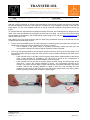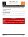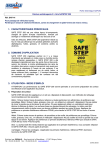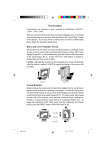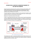
1
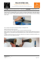
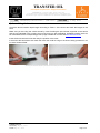
TRANSFER OIL thermoplastic and ptfe hoses – fittings and assemblies Transfer Oil S.p.A. – via sacca 64 – 43052 – Colorno – Parma – Italy tel. +39 0521 3139 – fax +39 0521 814160 – [email protected] – www.transferoil.com vat and business register of parma: IT 02306450343 – share capital: EUR 2.500.000 fully paid‐up Title Assembling instructions – OSM hoses Issue date 20 May 2015 OFF SHORE MASTER Hose range Assembling instructions Scope Transfer Oil is aware that hose and fittings are two semi-manufactured elements of a finished product: the “hose assembly”. The quality level of the “hose assembly” equals the LOWEST level among those declared for the hose, for the fittings and for the coupling. The choice of original Transfer Oil fittings is therefore a primary condition for the use of Transfer Oil hose assembly. Following pages shows the fittings and ferrule categories, with dimensions, and the compatible hose diameters. Other operations to improve the crimping operation such as use of positioning devices have to be separately evaluated. WARNING! TRANSFER OIL ADVISE THAT HOSE ASSEMBLIES REQUIRE CAUTION WHEN PRODUCED AND WHEN IN USE NOT ONLY TO PROVIDE LONG SERVICE BUT ALSO TO GUARD AGAINST POTENTIALLY DANGEROUS FAILURE. SERIOUS INJURY, DEATH AND DESTRUCTION OF PROPERTY CAN RESULT FROM THE RUPTURE OR BLOWING-APART OF HOSE ASSEMBLY THAT IS BADLY ASSEMBLED OR ABUSED IN APPLICATION. Contents: 1) Preparing the assembly .............................................................................................................................2 2) Assembling the ferrule ...............................................................................................................................3 3) Assembling the insert ................................................................................................................................4 4) Crimping procedure ...................................................................................................................................5 5) Checking the bore collapse .......................................................................................................................6 6) Pressure testing.........................................................................................................................................7 7) Annex ........................................................................................................................................................8 Table 1: Crimping details and proof pressures .........................................................................................8 Extra care is taken in the preparation of this data sheet but Transfer Oil is not responsible for any inadvertent typographical errors or omissions. Information subject to change without notice. The information in this document is only accurate as of the date of publication. Transfer Oil S.p.A. Last modify: May 20, 2015 Printed: May 20, 2015 Page 1 of 8 TRANSFER OIL thermoplastic and ptfe hoses – fittings and assemblies Transfer Oil S.p.A. – via sacca 64 – 43052 – Colorno – Parma – Italy tel. +39 0521 3139 – fax +39 0521 814160 – [email protected] – www.transferoil.com vat and business register of parma: IT 02306450343 – share capital: EUR 2.500.000 fully paid‐up Title Assembling instructions – OSM hoses Issue date 20 May 2015 1) Preparing the assembly Cut the hose to the right length taking care of making a perfectly perpendicular cut. Be certain that the equipment used is a suitable hose cutting machine fit for purpose. Follow safety instructions supplied with the cutting machine. Safety glasses should always be worn when cutting any hose with rotating blade cutters. Cutting the hose The cut must be clean without excessively melting or crushing the hose. Blades should be kept sharp at all times. Remove burrs and/or other residual from the cut surface externally and internally. Make sure that no dust, impurities or material residual from the cutting operation entered in the hose, as solid particles can contaminate the fluid and damage the pump or other components in the high-pressure circuit. In addition, assembly flushing can be performed, depending on the degree of cleanliness required in your application and on your standard procedures. Use a proper tool to remove burrs and/or residual from the cut surface. Transfer Oil S.p.A. Last modify: May 20, 2015 Printed: May 20, 2015 Page 2 of 8 TRANSFER OIL thermoplastic and ptfe hoses – fittings and assemblies Transfer Oil S.p.A. – via sacca 64 – 43052 – Colorno – Parma – Italy tel. +39 0521 3139 – fax +39 0521 814160 – [email protected] – www.transferoil.com vat and business register of parma: IT 02306450343 – share capital: EUR 2.500.000 fully paid‐up Title Assembling instructions – OSM hoses Issue date 20 May 2015 2) Assembling the ferrule Check the ferrule insertion depth length according to Table 1 of the Annex and mark this length on the hose. Make sure you are using the correct ferrule by cross-checking the part number engraved on the ferrule and the one indicated in the crimping chart of the hose you are assembling. Updated crimping chart can be downloaded at the corresponding product page available at our web site www.transferoil.com. Insert the ferrule onto the hose and verify the position of the mark. If the end of the ferrule does not match the mark, this could be a sign of incorrect cutting procedure or an incorrect ferrule utilized. Marking the insertion depth of the ferrule and then put insert into the hose. Transfer Oil S.p.A. Last modify: May 20, 2015 Printed: May 20, 2015 Page 3 of 8 TRANSFER OIL thermoplastic and ptfe hoses – fittings and assemblies Transfer Oil S.p.A. – via sacca 64 – 43052 – Colorno – Parma – Italy tel. +39 0521 3139 – fax +39 0521 814160 – [email protected] – www.transferoil.com vat and business register of parma: IT 02306450343 – share capital: EUR 2.500.000 fully paid‐up Title Assembling instructions – OSM hoses Issue date 20 May 2015 3) Assembling the insert Push the insert into the hose end. Use of a lubricating oil should not normally be required and should not automatically be used. If required, also a rubber mallet can be used to gently tap the insert into the hose end. However, in the event lubrication is required, this should be the smallest amount possible and applied by wet sponge to the end of the insert. Incorrect lubricating, as it is visible in the pictures below, may cause problems at the fittings. Do not fully immerse the insert tail in oil! Oil dipping of the insert can result in lubrication fluid trapped into insert tail grooves, which can be the cause of dangerous fitting blow-offs when the hose assembly is pressurized. None of our OSM hoses are intended to be used in applications with concentrations of oxygen above 26%, however never use lubrication oil when assembling hoses that are intended to be used with concentrations of oxygen above 26%. WRONG USE OF LUBRICATING CORRECT USE OF LUBRICATING Transfer Oil S.p.A. Last modify: May 20, 2015 Printed: May 20, 2015 Page 4 of 8 TRANSFER OIL thermoplastic and ptfe hoses – fittings and assemblies Transfer Oil S.p.A. – via sacca 64 – 43052 – Colorno – Parma – Italy tel. +39 0521 3139 – fax +39 0521 814160 – [email protected] – www.transferoil.com vat and business register of parma: IT 02306450343 – share capital: EUR 2.500.000 fully paid‐up Title Assembling instructions – OSM hoses Issue date 20 May 2015 4) Crimping procedure This procedure is valid for pallet swaging machines, using eight dies crimping sets. Use the crimping diameter recommended for the hose being assembled to choose the most suitable dies available for the machine in use. You can also consult the machine user manual to identify the most suitable die set. Using inadequate dies set, for example too small, will result in irregular crimping surface and ridges, which can be the cause of dangerous fitting blow-offs, or high pressure fluid leakages, when the hose assembly is pressurized. After having adequately set the crimping machine parameters, start crimping the ferrule making sure that the whole length is being crimped by the dies. After having reached the target crimping diameter, slightly open the dies, and then rotate the hose by 1/16 of turn, or 22.5°, this in order to smooth the slight ridges generated during the first crimping, and crimp the ferrule again. Extra care has to be given in removing ridges and obtaining a round and uniform crimp. Reaching the recommended crimping diameter does not mean that the hose is adequately crimped! The crimping diameter is purely an indication to select the optimal dies set and to set the crimping machine target parameter. To have full evidence of a correct crimping, the bore collapse must be verified. See next section for detailed instructions. Even if the crimping diameter has been achieved but the recommended bore collapse has not been reached, it is necessary to adjust the crimping diameter in steps of 0,05 mm until the right bore collapse is exactly achieved. Once the crimping operation is complete, check the position of the ferrule and the mark done with the felt-tip pen in the first step. If the end of the ferrule does not match the mark, reject the assembly. To avoid presence of ridges on the ferrule after swage, position protruding ridges central to crimping dies. Transfer Oil S.p.A. Last modify: May 20, 2015 Printed: May 20, 2015 Page 5 of 8 TRANSFER OIL thermoplastic and ptfe hoses – fittings and assemblies Transfer Oil S.p.A. – via sacca 64 – 43052 – Colorno – Parma – Italy tel. +39 0521 3139 – fax +39 0521 814160 – [email protected] – www.transferoil.com vat and business register of parma: IT 02306450343 – share capital: EUR 2.500.000 fully paid‐up Title Assembling instructions – OSM hoses Issue date 20 May 2015 5) Checking the bore collapse After the crimping operation, as result of the compression of the ferrule crimped over the hose, the insert tail internal diameter is reduced. This reduction is defined as “bore collapse” and when in line with its target figure, it is the most reliable evidence of having achieved a suitable compression across the layers. To measure that the appropriate bore collapse has been achieved, the suitable go/no-go gauge must be used. A list of the specified go/no-go gauges can be found in the table 1 of the annex or in the crimping chart available for download in the corresponding product page of our web site www.transferoil.com as well as instruction for use. Both sides of the bore gauge matching with the hose being assembled need to be introduced into the crimped end that needs to be verified: The go side (recognizable by the G letter engraved) of the bore gauge must slide freely through the whole length of the insert without interference as shown in picture 1. o If the mandrel of the gauge stops or interferes excessively inside the insert tail, the compression achieved is excessive and the assembly must be rejected. The no-go side (recognizable by the NG letters engraved and the red ring) of the bore gauge must stop approximately half way through the insert (see the correct position indicated by the green arrow on picture 2). o If the mandrel of the no-go side of the bore gauge stops before, approximately at the ferrule collar / insert shoulder as indicated by the red arrow in picture 2, the compression is achieved at the wrong area, and the assembly must be rejected. o If the mandrel of the no-go side of the bore gauge can slide though the whole length of the insert, then – even if the crimping diameter is correct – the compression achieved is not enough. The ferrule must be newly crimped following the procedures indicated in the earlier sections, reducing the crimping diameter in steps of 0,05 mm, and checking the bore collapse at every step. Do this until the no go side of the gauge stops in the right position and the go side can freely slide through the whole length. 1. Go side must slide through the whole length of the insert Transfer Oil S.p.A. Last modify: May 20, 2015 Printed: May 20, 2015 2. The no‐go side must stop half way through the insert Page 6 of 8 TRANSFER OIL thermoplastic and ptfe hoses – fittings and assemblies Transfer Oil S.p.A. – via sacca 64 – 43052 – Colorno – Parma – Italy tel. +39 0521 3139 – fax +39 0521 814160 – [email protected] – www.transferoil.com vat and business register of parma: IT 02306450343 – share capital: EUR 2.500.000 fully paid‐up Title Assembling instructions – OSM hoses Issue date 20 May 2015 6) Pressure testing Transfer Oil OSM hose assemblies should be pressure-tested before being delivered to the customer. The respective test pressures are shown in Table 1 of the Annex. Pressure testing must be performed in a closed pressure test stand and with the assembly complete with all the possible protections and accessories that customer has required. The high pressure hose assembly must be kept under test pressure for 30 to 60 seconds, accordingly with EN ISO 1402. During pressure testing there shall be no evidence of hose leakage, leakage at the hose / coupling interface or failure of the coupling at the specified pressure. If any of these malfunctioning are observed, the hose assembly shall be rejected. Once the test has been performed, it is recommended to check whether the fittings have warmed up during the pressure test by laying on your hand, after having thoroughly checked that there is no residual pressure in the hose assembly. A warm ferrule could be a sign of a leakage presence during the pressure test. After the high pressure testing successfully passed, the hose assembly is ready for dispatch and no other modification to the assembly must be performed. WARNING! IN PRESENCE OF A LEAKING ASSEMBLY, THE HOSE MUST NOT BE DELIVERED TO THE CUSTOMER AS IT WOULD FAIL AFTER A SHORT PERIOD IN SERVICE WITH SERIOUS RISK OF PROPERTY DAMAGES, INJURIES OR DEATH. THE LEAKING TERMINATION MUST BE CUT OFF AND THE HOSE BE REASSEMBLED. Transfer Oil S.p.A. Last modify: May 20, 2015 Printed: May 20, 2015 Page 7 of 8 TRANSFER OIL thermoplastic and ptfe hoses – fittings and assemblies Transfer Oil S.p.A. – via sacca 64 – 43052 – Colorno – Parma – Italy tel. +39 0521 3139 – fax +39 0521 814160 – [email protected] – www.transferoil.com vat and business register of parma: IT 02306450343 – share capital: EUR 2.500.000 fully paid‐up Title Assembling instructions – OSM hoses Issue date 20 May 2015 7) Annex Table 1: Crimping details and proof pressures 168 - OFF SHORE MASTER 3K Part no. Insertion depth Bore collapse Size Ferrule mm inch mm inch GO/NO GO Gauge Part No. Crimp OD expect mm Proof pressure inch bar psi 1687 DN20 SAL171 52,2 2,036 0,7 0,027 SXC872 34,1 1,330 420 6000 1688 DN25 SAL181 53,4 2,083 0,7 0,027 SXC881 42,3 1,650 420 6000 060 - OFF SHORE MASTER 5K Part no. Insertion depth Bore collapse Size Ferrule mm inch mm inch GO/NO GO Gauge Part No. - Crimp OD expect Proof pressure mm inch bar psi - - 700 10000 0601 DN5 SAF111 24,2 0,944 - - 0602 DN6 SAF121 31,3 1,221 0,7 0,027 SXC821 15,9 0,620 700 10000 0604 DN10 SAF141 36,7 1,431 0,7 0,027 SXC841 21,4 0,835 700 10000 0605 DN13 SAF151 46,0 1,794 0,7 0,027 SXC852 27,4 1,069 700 10000 0607 DN20 SAF171 53,4 2,083 0,7 0,027 SXC872 35,4 1,381 700 10000 0608 DN25 SAF181 55,7 2,172 1,3 0,051 SXC882 45,0 1,755 700 10000 169 - OFF SHORE MASTER 10K Insertion depth Bore collapse mm mm inch 1,221 0,7 0,027 Part Size Ferrule no. 1692 DN4 SAF121 31,3 Transfer Oil S.p.A. Last modify: May 20, 2015 Printed: May 20, 2015 inch GO/NO GO Gauge Part No. SXC821 Crimp OD expect mm inch Proof pressure bar psi 16,8 0,655 1400 20000 Page 8 of 8