1
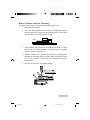
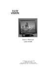
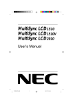
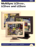
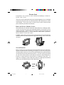
Errata sheet
Listed below are revisions to user’s manual for MultiSync LCD1510 /
1510V / 1810 / 2010.
This new revision of the monitor does not include shipping screw even though
some picture may have the screw hole described in the “Quick Start” section
of the manual. If you raise, lower or rotate screen or remove monitor stand,
please follow the procedure stated below.
Raise and Lower Monitor Screen
The monitor may be raised or lowered in either Portrait or Landscape mode.
To raise or lower screen, place one hand under bottom of screen, lift or lower
slightly (Figure RL.1) and simultaneously push the button on the bottom back
of the stand (Figure RL.2). Screen will lower while button is pushed in.
Release button to lock screen in place.
Caution: Although the monitor has been designed not to lower automatically
when the button is pushed, ALWAYS support the bottom of the screen with
one hand.
Figure RL.2
Figure RL.1
Screen Rotation
Before rotating, the screen must be raised to the highest level to avoid knocking the screen on the desk or pinching your fingers. To raise the screen, place
one hand under bottom of screen, lift up and simultaneously push the button
on the bottom back of the stand (Figure RL.2). To rotate screen, place hands
on each side of the monitor screen and turn clockwise from Landscape to
Portrait or counter-clockwise from Portrait to Landscape (Figure R.1). To
toggle the orientation of the OSM menu between Landscape and Portrait
modes, press the RESET button while OSM menu is off.
Figure R.1
Figure R.1
Errata sheet
1
99.4.1, 8:47 PM
Remove Monitor Stand for Mounting
To prepare the monitor for alternate mounting purposes:
1. Disconnect all cables.
2. Place one hand under bottom of screen, lift up and simultaneously push the button on the bottom back of the stand
(Figure RL.2) to the maximum height.
55mm
40mm
Figure S.1
Figure
S.1
3. Place monitor face down on a non-abrasive surface. Place
the screen on s 2-inch platform so that the stand is parallel
with the surface (Figure S.1).
4. Remove cable cover. Remove the 4 screws connecting the
monitor to the stand and lift off the stand assembly (Figure
S.2). The monitor is now ready for mounting in an alternate manner.
5. Reverse this process to reattach stand.
3
4
2
1
FigureS.2
S.2
Figure
Part Number TBD
Printed in Japan
Errata sheet
2
99.4.1, 8:47 PM