1
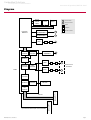
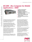
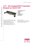
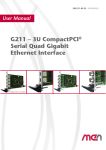
Embedded Solutions
for Transportation and Industrial Markets
www.men.de/products/02F218-.html
F218 – 3U CompactPCI® PowerPC® MPC8314
Slave CPU Board
n 32-bit/33-MHz CompactPCI®
n 4HP peripheral slot or stand-alone function
n PowerPC® MPC8314, 266 MHz
n Host CPU communication via Ethernet
n Ultra fast boot < 2 seconds
n Flexible FPGA-Flash structure
n 256 MB SDRAM, 16 MB Flash
n Front I/O: 2 Gb Ethernet, 1 UART via
SA-Adapter™
n Rear I/O: user-defined via FPGA (option)
n -40 to +85°C with qualified components
The F218 is a 3U 4HP CompactPCI® slave CPU card
which can be used as an Ethernet diagnosis buffer. It
communicates with the host CPU board via Ethernet.
The F218's processor is connected to the CompactPCI®
bus via the FPGA. The connection is realized via two
Ethernet controllers inside the FPGA so that the host
CPU board sees the F218 as an Ethernet device. This
kind of connection is similar to a front connection of 2
CPU boards via Ethernet cable.
The F218 is controlled by the PowerPC® MPC8314, an
e300 core processor with a performance of up to 266
MHz. The core is built on Power Architecture
technology and is a cost-effective, low-power, highly
F218 Data Sheet / 2013-02-06
integrated processor that addresses the requirements of industrial
applications.
As memory the F218 offers 256 MB DDR2 SDRAM, 16 MB Flash and
optionally 1 MB non-volatile FRAM.
Two Gigabit Ethernet interfaces and one serial interface which is realized
via an additional SA-Adapter™ are available at the front panel. As an
option, the onboard FPGA offers the possibility to realize an additional
Fast Ethernet and two UART interfaces which can be accessed via
SA-Adapters™ on a second front panel slot.
The F218 is qualified for operation in a -40°C to +85°C temperature
range. It operates in VxWorks® and Linux environments and is supported
by the U-Boot Universal bootloader. The boards boots a VxWorks®supported BSP in less than 2 seconds.
Page 1
Embedded Solutions
for Transportation and Industrial Markets
www.men.de/products/02F218-.html
Diagram
System
SDRAM
DDR2
Flash
FRAM
F
Front connector
R
Rear I/O connector
Options
Ethernet
10/100/1000Base-T
Ethernet
10/100/1000Base-T
PowerPC®
MPC8314
UART
F
SA
SA-Adapter
B
Onboard connector
F
B
SA
F
PCI Bus
PCI
Interface
Ethernet
10/100Base-T
Ethernet
Controller
F
Wishbone
UART
Ethernet
Controller
B
SA
F
Second Front
Panel Slot
UART
Controller
FPGA
UART
B
SA
F
Ethernet
Controller
Wishbone
SPI
Controller
SPI Flash
CompactPCI® J1
PCI
Interface
Up to 80 user-defined I/O lines from FPGA
F218 Data Sheet / 2013-02-06
CompactPCI® J2
PCI Bus
Page 2
Embedded Solutions
for Transportation and Industrial Markets
www.men.de/products/02F218-.html
Technical Data
CPU
n
PowerPC® MPC8314 PowerQUICC™ II Pro
o 266 MHz
Memory
n
256 MB SDRAM system memory
o Soldered
o 133 MHz memory bus frequency
16 MB Flash
1 MB non-volatile FRAM optional
Serial EEPROM 2 KB for factory settings
4 MB SPI Flash (FPGA-controlled)
n
n
n
n
I/O
n
n
n
Front Connections
Ethernet
o Two 10/100/1000Base-T Ethernet channels
o One 10/100Base-T Ethernet channel (optional, FPGA-controlled, on 4-pin Lemo connector)
o RJ45 connector at front panel
o Two status LEDs for each channel
One RS232 or RS422 UART via SA-Adapter™
o D-Sub connector at front panel
o Via 10-pin onboard connector
o Data rates up to 230,400 bit/s
o Handshake lines: DTR, RTS, CTS
80 GPIO lines from FPGA
o Accessible via J2 rear I/O connector
n
Two Ethernet (RJ45)
COM1 (D-Sub)
Rear I/O
n
80 GPIO lines from FPGA
FPGA
n
The FPGA offers the possibility to realize additional I/O functionality. See Options
Miscellaneous
n
Supply voltage supervision
Four programmable user LEDs
n
n
CompactPCI® Bus
n
n
n
n
Busless Operation
n
n
Compliance with CompactPCI® Core Specification PICMG 2.0 R3.0
Peripheral slot
32-bit/33-MHz
V(I/O): +3.3 V
Board can be supplied with +5 V only, all other voltages are generated on the board
Backplane connectors used only for power supply
Electrical Specifications
n
Supply voltage/power consumption:
o +5 V (-3%/+5%), tbd typ./max.
Mechanical Specifications
n
Dimensions: conforming to CompactPCI® specification for 3U boards
Front panel: 4 HP / 8 HP with ejector
Weight: 166 g (w/o heat sink and SA-Adapter™)
n
n
Environmental Specifications
n
n
n
n
n
n
n
n
n
F218 Data Sheet / 2013-02-06
Temperature range (operation):
o -40..+85°C (qualified components)
o Airflow: min. 1.0 m/s
Temperature range (storage): -40..+85°C
Relative humidity (operation): max. 95% non-condensing
Relative humidity (storage): max. 95% non-condensing
Altitude: -300 m to + 3,000 m
Shock: 15 g, 11 ms
Bump: 10 g, 16 ms
Vibration (sinusoidal): 1 g, 10..150 Hz
Conformal coating on request
Page 3
Embedded Solutions
for Transportation and Industrial Markets
www.men.de/products/02F218-.html
Technical Data
MTBF
n
427,994h @ 40°C according to IEC/TR 62380 (RDF 2000)
Safety
n
PCB manufactured with a flammability rating of 94V-0 by UL recognized manufacturers
EMC
n
Conforming to EN 55022 (radio disturbance), IEC1000-4-2 (ESD) and IEC1000-4-4 (burst)
BIOS
n
U-Boot Universal Boot Loader
Software Support
n
Linux (in preparation)
VxWorks® (in preparation)
QNX® (on request)
For more information on supported operating system versions and drivers see Downloads.
n
n
n
FPGA
This product offers the possibility to add customized I/O functionality in FPGA.
Flexible Configuration
n
n
n
FPGA Capabilities
n
n
F218 Data Sheet / 2013-02-06
Customized I/O functions can be added to the FPGA.
It depends on the board type, pin counts and number of logic elements which IP cores make sense and/or
can be implemented. Please contact MEN for information on feasibility.
You can find more information on our web page "User I/O in FPGA"
FPGA Altera® Cyclone® III EP3C40
o 39,600 logic elements
o 1,134 Kbits total RAM
Connection
o Total available pin count: 80 pins
o Functions available via rear I/O connector J2
o SA-Adapters™ are used to realize the physical lines.
Page 4
Embedded Solutions
for Transportation and Industrial Markets
www.men.de/products/02F218-.html
Configuration & Options
Standard Configurations
Article No.
Ethernet
System RAM
Flash
FRAM
02F218-00
2 Gigabit Ethernet
256 MB
16 MB
none
Options
Memory
n
Non-volatile FRAM
o 0 MB, 1 MB
I/O
n
n
Third Ethernet interface (10/100MBit/s) at front via 4-pin Lemo connector
o Controlled via FPGA
All three Ethernet (10/100MBit/s) interfaces via 4-pin Lemo connectors (up to 3 on 4HP front panel)
2 additional FPGA interfaces via MEN SA-Adapters™ (e.g. CAN, IBIS, UART, binary I/O) on 8HP front panel
80 I/O lines from FPGA for user-defined functionality on CompactPCI® J2 connector
Mechanical
n
4HP or 8HP
Cooling Concept
n
Also available with conduction cooling in MEN CCA frame
n
n
Please note that some of these options may only be available for large volumes. Please ask our sales staff for more information.
Ordering Information
Standard F218 Models
02F218-00
SA-Adapters™
You can find a more detailed overview of possible carrier board/SA-Adapter™ combinations along with
software support in our option matrix (PDF).
Software: Firmware/BIOS
PowerPC® MPC8314, 2x Gigabit Ethernet, 256 MB DRAM, 16 MB Flash, -40..+85°C with
qualified components
08SA01-00
RS232, not optically isolated, 0..+60°C
08SA02-01
RS422/485, full duplex, optically isolated, 0..+60°C
08SA02-07
RS422/485, full duplex, optically isolated, -40..+85°C screened
08SA03-00
1 RS232, optically isolated, 0..+60°C
08SA03-01
1 RS232, optically isolated, -40..+85°C screened
This product uses the U-Boot bootloader available from DENX together with board-specific additions from
MEN.
14F218-00
U-Boot Bootloader (MEN) for F218
For operating systems not mentioned here contact MEN sales.
Documentation
Compare Chart 3U CompactPCI® / PlusIO CPU cards » Download
Compare Chart 3U CompactPCI® / PlusIO peripheral cards » Download
20F218-00
F218 Data Sheet / 2013-02-06
F218 User Manual
Page 5
Embedded Solutions
for Transportation and Industrial Markets
www.men.de/products/02F218-.html
Contact Information
Germany
France
USA
MEN Mikro Elektronik GmbH
Neuwieder Straße 3-7
90411 Nuremberg
Phone +49-911-99 33 5-0
Fax +49-911-99 33 5-901
MEN Mikro Elektronik SA
18, rue René Cassin
ZA de la Châtelaine
74240 Gaillard
Phone +33 (0) 450-955-312
Fax +33 (0) 450-955-211
MEN Micro Inc.
860 Penllyn Blue Bell Pike
Blue Bell, PA 19422
Phone (215) 542-9575
Fax (215) 542-9577
[email protected]
www.men.de
[email protected]
www.men-france.fr
[email protected]
www.menmicro.com
The date of issue stated in this data sheet refers to the Technical Data only. Changes in ordering information given herein do not affect the date of issue. All brand or product names are
trademarks or registered trademarks of their respective holders.
MEN is not responsible for the results of any actions taken on the basis of information in the publication, nor for any error in or omission from the publication.
MEN expressly disclaims all and any liability and responsibility to any person, whether a reader of the publication or not, in respect of anything, and of the consequences of anything,
done or omitted to be done by any such person in reliance, whether wholly or partially, on the whole or any part of the contents of the publication.
The correct function of MEN products in mission-critical and life-critical applications is limited to the environmental specification given for each product in the technical user manual.The
correct function of MEN products under extended environmental conditions is limited to the individual requirement specification and subsequent validation documents for each product
for the applicable use case and has to be agreed upon in writing by MEN and the customer.Should the customer purchase or use MEN products for any unintended or unauthorized
application, the customer shall indemnify and hold MEN and its officers, employees, subsidiaries, affiliates, and distributors harmless against all claims, costs, damages, and expenses,
and reasonable attorney fees arising out of, directly or indirectly, any claim or personal injury or death associated with such unintended or unauthorized use, even if such claim alleges
that MEN was negligent regarding the design or manufacture of the part.
In no case is MEN liable for the correct function of the technical installation where MEN products are a part of.
Copyright © 2013 MEN Mikro Elektronik GmbH. All rights reserved.
F218 Data Sheet / 2013-02-06
Page 6