1
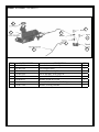
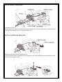
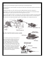
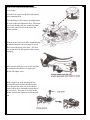
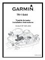
TR-1 Gold
Throttle Actuator
Installation Instructions
Honda 8 HP 1987-2000
PN 906-1160-00
Parts: Kit Number: 120-0052-01
8
7
1
6
4
5
3
2
ITEM
1
2
3
4
5
6
7
8
PART NUMBER
130-0029-01
301-0003-00
370-0059-00
310-0004-04
380-0015-00
310-0040-23
310-0004-10
310-0073-06
DESCRIPTION
Throttle Actuator Assembly
Rod, Stainless Steel
Bracket, Throttle, 8hp Honda
Screw, Machine, 4040, PPH, SS
Spacer, 3/16” Tall x .125 ID
Washer, Nylon #4 .25 OD
Screw, Machine #4 - 40 x 5/8 Phillips
Washer, Locking, Internal
QTY
1
1
1
1
1
1
1
1
Step One: Remove Throttle Rod
Loosen the stop screw.
Using the tiller grip, rotate the throttle arm until the throttle rod is free from the holder on the throttle arm.
Lift the throttle rod and remove it from the throttle lever.
Step Two: Install the throttle bracket
Slide the throttle bracket under the throttle lever.
Secure the throttle bracket to the throttle lever using the 4-40 x 9/16 phillips head screw and the 1/4 inch
diameter spacer and the washer.
Step Three: Install the throttle loop link
Hook the loop end of the throttle loop link around the spacer on the throttle bracket.
Using the tiller grip, rotate the throttle arm and place the other end of the throttle loop link into the holder on
the throttle arm.
With the tiller handle set to idle or full slow position, adjust the throttle loop link so that there is
approximately 1 mm clearance between the inside edge of the loop and the spacer on the throttle bracket.
While holding the loop flat against the throttle bracket tighten the stop screw.
Rotate the tiller handle from idle to max throttle and verify that the throttle loop link does not bind anywhere.
With the tiller handle set to idle, rotate the throttle bracket with your finger from idle to maximum throttle
and verify it does not bind on the throttle loop link. If any binding occurs, readjust the stop screw.
Step Four: Install the throttle actuator assembly
Verify that the outside edge of the stop block is
approximately flush with the end of the motor
lead screw. If not, loosen the stop block set
screw and slide the stop block to the end of
the shaft. Retighten the set screw. Push the
motor lead screw until the stop block activates
(closes) the limit switch. The inner edge of the
stop block should be almost in contact with the
motor. If necessary, loosen the circuit board
mounting screws and slide the circuit board
forward or backward to allow the stop block to
activate the limit switch properly.
Remove one of the bolts holding down the
recoil starter.
Place the lock washer on the bolt and restart it
in the mounting hole.
Place the flange of the actuator assembly under
the lock washer and tighten the bolt. The motor
lead screw should point just outside the outer
edge of the square block on the end of the
throttle bracket.
With the motor lead screw fully extended rotate
the throttle bracket with your finger to verify
that it clears the motor lead screw. If it does
not, loosen the bolt and reposition the actuator
assembly.
Make sure the tiller grip is set to idle and that
the carburetor throttle lever is against the
throttle idle adjust screw.
With a slight loop in the throttle pull line
between the motor and the throttle bracket,
place the pull line in the slot of the throttle
bracket and wrap it around the bracket and in
the slots twice. Place the lock screw in the
throttle bracket and tighten to secure the pull
line.
Testing the Actuator Functions:
Please refer to the startup section of your owner’s manual before operating your handheld and
running the throttle actuator.
1. With the outboard in the water, or with a proper coolant flush device connected, start the
outboard and let it warm up to operating conditions. Be prepared to kill the outboard ignition if
the idle speed is too high when the engine starts.
2. With the outboard in idle position make sure there is proper slack in the pull string on the
throttle actuator. If the motor does not go to idle, reposition the string by loosening the pinch
screw on the brass pivot.
3. Using the UP ARROW button on the Handheld verify that the engine rpm’s go up. Using the
IDLE/RESUME button on the handheld verify that the engine returns to idle. Check the throttle up
and down several times along with the idle/res and verify that you don’t have any problems.