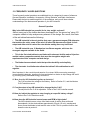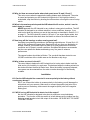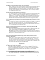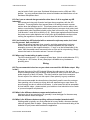
1
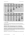
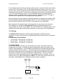
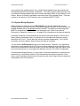
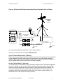
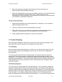
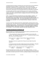
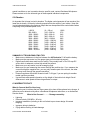
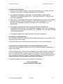
For Use With Trace C-40 External Controller and Dump Load Owner’s Manual Version C Wind Turbine Serial Number ___________________________________ AIR Industrial Manual Document #0054 REV C NOTICES: •= This information is believed to be reliable; however, Southwest Windpower, Inc assumes no responsibility for inaccuracies or omissions. The user of this information and product assumes full responsibility and risk. •= All specifications are subject to change without notice. •= Wind generators, like other sources of electrical power, must be installed following the guidelines established by the National Electrical Code & local regulations. Consult a local electrical contractor for details and regulations. •= For your convenience and protection write the serial number of your wind turbine on the front of this manual. Store your purchase invoice with this manual as well. You will need this information in the event of a warranty claim. It also helps the customer service department at Southwest Windpower when you have questions about your specific turbine. Thank you. Made in the USA by: Southwest Windpower, Inc. 2131 N. First Street Flagstaff, Arizona 86004 Phone: (928) 779-9463 Fax: (928) 779-1485 E-mail: [email protected] Web: www.windenergy.com AIR Industrial is a trademark of Southwest Windpower 1998 Southwest Windpower, Inc. SOUTHWEST WINDPOWER 10/16/2001 2 AIR Industrial Manual Document #0054 REV C CONGRATULATIONS! You have just purchased the most advanced small wind turbine in the world! We believe you will find it easy to install your AIR Industrial; however, it is important that you read this manual thoroughly prior to installation to assure proper performance and safety. Southwest Windpower has over 14 years of experience in designing and manufacturing small wind generators. Up to mid-2001, over 42,000 AIRs have been sold throughout the world. What makes the AIR Industrial unique in comparison to other turbines is the use of state-ofthe-art technology like Iron Boron Neodymium magnets, carbon reinforced engineering thermoplastics, high-quality aluminum and all stainless steel hardware and integrated electronics. AIR Industrial offers external regulation in combination with a dedicated load to Ensure reliable operation in the most extreme wind conditions. If you have any further questions after reading the manual thoroughly, please contact your authorized distributor/dealer or Southwest Windpower, Inc. Enjoy. SOUTHWEST WINDPOWER 10/16/2001 3 AIR Industrial Manual Document #0054 REV C I. Installation 1. Safety Precautions………………………………………………………... 5 1.1 Mechanical Hazards 5 1.2 Electrical Hazards 5 1.3 Installation 6 1.4 Operation 6 2. Package Contents………………………………………………………… 7 3. Wiring and Installation Procedures……………………………………. 8 3.1 Wiring………………………………………………………………….. 9 3.1.1 Electrical Connections 9 3.1.2 Wire Size 9 3.1.3 Grounding 10 3.1.4 Fusing 11 3.1.5 Stop Switch 11 3.1.6 System Wiring Diagrams 12 3.2 Mounting to Tower…………………………………………………… 14 3.2.1 Attaching to Pole 15 3.3 Hub and Rotor Assembly…………………………………………… 16 3.3.1 Mounting Blades 16 3.3.2 Mounting Hub and Blades 17 3.3.3 Attaching Nose Cone 17 3.4 Step-By-Step Instructions………………………………………….. 17 4. Testing………………………………………………………………………. 20 4.1 General Discussion of Operation…………………………………. 20 4.1.1 Alternator 20 4.1.2 Regulator 20 4.1.3 Blades 20 4.1.4 Four Spinning Conditions 21 4.1.5 Industrial Features…………………………………………….. 21 4.2 Bench Testing………………………………………………………… 22 4.3 Performance Testing………………………………………………… 23 5. Trouble Shooting………………………………………………………….. 23 5.1 Assembly………………………………………………………………. 23 5.2 Electrical System………………………………….…………………. 23 5.3 Elevation ………………………………………………………………. 25 6. Warranty Policy……………………………………………………………. 25 II. Appendix 7. Specifications……………………………………………………………… 27 7.1 Technical Specifications 27 7.2 Sphere of Operation 28 7.3 Exploded View of AIR Industrial 28 8. Maintenance………………………………………………………………... 29 9. System Requirements and Considerations……………………………30 9.1 Batteries 30 10. Siting……………………………………………………………………….. 31 11. Towers………………………………………………………………………33 11.1 Guyed Towers 33 11.2 Roof Top Mounting 33 12. Frequently Asked Questions…………………………………………... 35 13. Accessories……………………………………………………………….. 41 14. References ………………………………………………………………… 44 SOUTHWEST WINDPOWER 10/16/2001 4 AIR Industrial Manual Document #0054 REV C I. INSTALLATION 1. SAFETY PRECAUTIONS The AIR Industrial has been designed with your safety in mind. However, there are inherent dangers involved with any electrical and/or mechanical equipment. Safety must be the primary concern as you plan the location, installation and operation of the wind turbine. At all times be aware of electrical, mechanical and rotor blade hazards. CAUTION: Severe damage to the unit can result from improper grounding. Failure to properly ground the turbine will void your warranty. 1.1 Mechanical Hazards Rotating blades present the most serious mechanical hazard. The AIR Industrial’s rotor blades are made of very strong thermoplastic. At the tip, the blades may be moving at velocities over 300 miles per hour. At this speed, the tip of a blade is nearly invisible and can cause serious injury. Under no circumstances should you install the turbine where a person could come in contact with moving rotor blades. CAUTION: DO NOT INSTALL THE TURBINE WHERE ANYONE CAN APPROACH THE PATH OF THE BLADES. 1.2 Electrical Hazard The AIR Industrial is equipped with sophisticated electronics designed to provide protection from electrical dangers. Please note that the inherent personal dangers from electrical current still exist, therefore caution should always be used when connecting this and other electrical devices. Heat in wiring systems is often a result of too much current flowing through an undersized wire or a bad connection. It is important to follow the wire sizing chart in Section 3.2.1 on page 9 to insure a safe electrical system. CAUTION: FOLLOW THE WIRE SIZING CHART IN SECTION 3.2.1 ON PAGE 9 TO HELP AVOID THE RISK OF AN ELECTRICAL FIRE. Batteries can deliver a dangerous amount of current. If a short occurs in the wiring from the batteries, a fire can result. In order to avoid this threat, a properly sized fuse or circuit breaker is required in the lines connecting to the battery. Refer to Section 3.2.4 on page 11 for fuse sizing information. CAUTION: FUSE ALL CONNECTIONS. FOLLOW THE FUSE SIZING GUIDELINES IN SECTION 3.2.4 ON PAGE 11 TO MINIMIZE THE RISK OF AN ELECTRICAL FAILURE. SOUTHWEST WINDPOWER 10/16/2001 5 AIR Industrial Manual Document #0054 REV C 1.3 Installation CAUTION: INSTALLATION PROCEDURES MUST BE PERFORMED AT GROUND LEVEL. CAUTION: MAKE SURE THAT ALL BATTERIES ARE DISCONNECTED THROUGHOUT THE INSTALLATION PROCESS. CAUTION: NEVER INSTALL THE AIR Industrial UPSIDE DOWN. Please follow these precautions during the installation process: •= •= •= •= Choose a calm day. THINK SAFETY! Have someone available to help during the installation process. Disconnect batteries from turbine wiring. Prior to attaching the wires to the C-40 external regulator, connect the wind turbine output lead wires (positive = red; negative = black) together near the battery to be sure that the rotor will not spin-up during installation. NOTE: Do not install the blade assembly until the turbine is mounted on the tower. This avoids damage to the blades during installation, and possibly to the installer’s eyes or body, as blade tips are sharp! 1.4 Operation Check support structures, blades, and electrical systems on a regular basis. •= The rotor blades are very strong; however, if they come in contact with a solid object, they can break. Use common sense when locating the turbine. •= When performing periodic inspections, or at any time when you must approach the path of the blades, shut down the turbine to stop the blades spinning, through the use of a stop switch. Alternatively, disconnect the power leads from the C-40 external regulator, to avoid electrical shock and connect the wind turbine output leads together to stop (slow down) the blades from rotating. Please refer to Figure 3 on page 11 on how to install a stop switch in your system. •= Please note that there is a short break-in period with new turbines. The bearings in both the turbine yaw and the turbine rotor will require approximately 60-100 hours of operation at rated windspeed (approximately 18 – 20 mph) before they are running at peak efficiency. During this break-in period, the turbine operation might appear sluggish. CAUTION: NEVER APPROACH THE TURBINE DURING OPERATION. USE COMMON SENSE AND PLEASE BE CAREFUL SOUTHWEST WINDPOWER 10/16/2001 6 AIR Industrial Manual Document #0054 REV C 2. Package Contents Compare the parts shown in Figure 1 with the contents of the box to insure that the box contains all necessary parts. If you have ordered the complete AIR Industrial package with the C-40 external regulator plus heat resistor box, they will be included in the box as along with the items shown in Figure 2. CAUTION: THE EDGES OF THE ROTOR BLADES ARE SHARP. PLEASE HANDLE WITH CARE. Figure 1 TEF-Gel SOUTHWEST WINDPOWER 5/16 Washer (2) 10/16/2001 7 AIR Industrial Manual Document #0054 REV C COMPONENTS INCLUDED WITH EXTERNAL CONTROLLER/LOAD DUMP: Trace C-40 controller Load dump resistor box Figure 2 3. Wiring and Installation Procedures Your AIR Industrial is shipped partially disassembled. Refer to Figure 6 on page 15 and Figure 7 on page 16 for assembly instructions. Read all procedures completely before you begin installing. NOTE: Do not install the blade assembly until the turbine is mounted on the tower. Required Tools: •= 5/16” hex key wrench (included) •= 3/16” hex key wrench (included) •= 5/32” hex key wrench (included) •= Torque wrench with 5/16”, 3/16”, and 5/32” hex bits •= An adjustable wrench, 15/16” open or box end wrench, or socket wrench. •= Soldering iron or propane torch •= Rosin core solder •= Electrical tape or 1/4” (6-7mm) heat shrink •= Wire strippers •= Wire crimpers SOUTHWEST WINDPOWER 10/16/2001 8 AIR Industrial Manual Document #0054 REV C 3.1 Wiring 3.1.1 Electrical Connections NOTE: Refer to and apply all Local and National Codes before installation. CAUTION: MAKE SURE THE TURBINE IS DISCONNECTED FROM THE BATTERIES DURING INSTALLATION. Avoid connecting different metals together (i.e., copper and aluminum). This will cause a galvanic reaction that will lead to a bad connection. When such connections cannot be avoided, consult your dealer or an electrical supply house for anti-oxidant compounds. Solder all wire termination ends. CAUTION: CONNECTIONS SHOULD BE INSPECTED PERIODICALLY FOR SIGNS OF CORROSION AND CLEANED WHEN NECESSARY. NOTE: The NEC requires that all electrical power cables be physically protected. Run the wires inside the tower or conduit for maximum protection. NOTE: The yaw can support a total of 150 lbs. (68 kg) in wire weight. For higher wire weights, you must install a strain relief to minimize the stress put on the hanging wires. The average weight of copper wire is .323 lb/in3 or 8941 kg/m3. Use the table below multiplied by length multiplied by the number of wires to calculate the approximate weight of your wiring system. AWG SIZE 14 12 10 8 6 4 3 2 1 0 2/0 3/0 4/0 Diam inches 0.0641 0.081 0.102 2 in 0.129 0.162 0.204 0.229 0.258 0.289 0.325 0.365 0.41 0.46 Square mm 2 mm 3.277 4.115 5.182 5.817 6.553 7.341 8.255 9.271 10.414 11.684 1.628 2.057 2.591 Wire Color Codes RED = positive, BLACK = negative, GREEN = earth ground. 3.1.2 Wire Size To select the appropriate size wire, measure the distance from the batteries to your AIR Industrial, then refer to the following wire sizing chart as minimum sizes. A larger sized wire will improve the performance of your system. This chart is sized for an average 12 mph (6 m/s) wind speed. If the wind speed average in your area is higher, use a larger size wire. Also, the charts below are for copper wire; for other wire types consult the NEC handbook for wire recommendations. NOTE: Battery disconnects may be necessary for compliance with electrical codes. SOUTHWEST WINDPOWER 10/16/2001 9 AIR Industrial Manual Document #0054 REV C 12V AIR Industrial System Wire Size Chart 24V AIR Industrial System Wire Size Chart * If your system requires this length of wire, consider using additional bus line(s) 3.1.3 Grounding As with all systems, properly grounding the turbine is very important in protecting the electronics for long-term operation. Grounding procedures must be followed along with any local grounding codes. IMPORTANT: SEVERE TURBINE DAMAGE CAN RESULT FROM IMPROPER GROUNDING! FAILURE TO GROUND PROPERLY WILL VOID YOUR WARRANTY. The turbine case is grounded to the green (earth) wire and the electronics to the black (negative) wire. As with all systems, it is very important to ground your tower and the turbine green earth wire, for lightning and static protection. Ground your battery bank negative, then the system grounds may be connected together by conductors with the same ratings as the positive and negative wires. (See Figure 4, p.13) IMPORTANT: ALL grounds must be connected together to insure a proper ground. SOUTHWEST WINDPOWER 10/16/2001 10 AIR Industrial Manual Document #0054 REV C For land based systems without an existing system ground, a ground electrode can be made from an 8 ft. (2.4 m) section of 3/4" (19 mm) galvanized pipe or conduit, or an 8 ft. (2.4 m) section of 5/8" (16 mm) copper plated iron or steel rod. This ground electrode must be buried completely beneath the soil, at no more than 45 degrees from vertical, or horizontally at least 2 1/2 ft. (75 cm) beneath the surface. It is recommended that the ground electrode be installed as close as possible to the system for maximum lightning protection. The base of the tower is also a good location for an appropriate surge arrestor. Delta manufactures surge arrestors for lightning protection. An example is the model LA 302RG surge arrestor. Contact: Delta Lighting Arrestors P.O. Box 750, Big Springs TX 79721, Phone (915) 267-1000 Fax (915) 267-1035 or your dealer for more information. Most vessels use the engine block or a submerge plate to carry the ground to the water. For installations on vessels the AIR Industrial should be grounded according to the American Boat and Yacht Council (ABYC). Ph. (410) 956-1050. The reference section in the appendix lists books that provide detailed information on grounding in marine applications. 3.1.4 Fusing The AIR Industrial is capable of producing high amperages. As with all electrical installations, you must fuse each of your turbines between the turbine and the C-40 external regulator. Recommended Circuit Breakers •= 12-volt model: 100 amps D.C. for each unit •= 24-volt model: 50 amps D.C. for each unit •= 48-volt model: 25 amps D.C. for each unit 3.1.5 Stop Switch A stop switch must be used with your AIR Industrial to provide a convenient method for shutting down the turbine. A 50-amp single-pole double-throw switch will work as a stop switch for most applications. These switches are available from Southwest Windpower and should be wired as shown in Figure 3. The switch disconnects the battery and then shorts the turbine causing the turbine to stop spinning (in high winds the blades will spin slowly). Shorting the turbine will not cause any damage or additional wear. This type of switch should not be used in applications where a code compliant switch is necessary, or for 12V turbines used in very high wind applications. NOTE: The center post must be positive from the turbine. Outside posts can be swapped as either positive or negative. Turbine Turbine Negative Positive - Black + Red Lead Lead - + + - C-40 + Stop Switch Figure 3 Stop Switch Wiring SOUTHWEST WINDPOWER 10/16/2001 11 AIR Industrial Manual Document #0054 REV C If you need a code compliant switch, then contact Schott Applied Power and purchase the AIR Industrial shutoff/circuit breaker combination. This code compliant switch features a pair of interlocked 60-amp breakers that work as both a stop switch and a circuit breaker for your turbine. Be sure to follow the installation instructions from Schott Applied Power. Their part number for this switch is 53-653 and they can be reached at 800-777-6609. 3.1.6 System Wiring Diagrams Before deciding on the wiring of your AIR Industrial, you should understand how your existing system is wired and how the C-40 external regulator operates. All AIR Industrials are shipped standard with an unregulated internal controller. This means an external regulator MUST be installed with the wind turbine and the battery bank. Refer to the General Discussion of Operation in Section 4.1.2 on page 20 for information on the external regulator. Southwest Windpower recommends wiring the turbine/C40 system directly to its own set of battery posts on the battery bank (via a protective circuit breaker and disconnect switch), rather than a DC “bus”. This will allow the turbine to operate independently. The C-40 will accurately monitor the battery charge state and charge as necessary. You can wire the AIR Industrial through most “power centers”. However, if you experience interference or pre-regulation by the C-40, due to voltage measured at the connection point which may be different than that at the battery (due to line resistance and other inputs on the same connection point) you must adjust the regulation set point in the C40 to compensate. Some external charging sources (i.e. solar panels, fuel-powered generators, additional wind generators etc.) can interfere with the C-40’s electronics and cause pre-regulation. If this occurs, test the possible interference by disconnecting the other charge sources to determine the possible source of interference. SOUTHWEST WINDPOWER 10/16/2001 12 AIR Industrial Manual Document #0054 REV C Figure 4: AIR Industrial Wiring Incorporating External Regulator and Load Dump: AIR industrial 403 Wind Turbine Generator Amp Meter C40 OR C60 Fuse or Breaker Battery Disconnect Stop Switch User Power Center Junction Box Turbine Positive Red Lead Tower Tower Ground (Optional) Chassis Ground Load Resistors Battery Bank Turbine Ground Green Lead Turbine Negative Black Lead Earth Ground Ground Rod For connecting multiple AIR Industrials, refer to Figure 5 below. There are two methods to wire multiple AIR Industrials. a) Each Turbine Wired Directly To Battery Each turbine incorporating it’s external regulator and dump load, operates as an independent system separate from other solar panels, gas generators or any other battery charging sources. Since the turbine has its own fuse, stop switch (optional), and wires, the turbine is able to independently communicate with and charge the battery. b) Each Turbine Wired To A Bus Bar You can wire two or more turbines, taking the output wires from the C-40 external regulators, to a “bus”, and then run one set of wires from the bus to the battery (when wiring multiple turbines, a bus bar system can save you money by reducing the wire cost). However, you must ensure that the resistance of the conductor from the bus bar to the battery is low enough so that under the combined full load output of all turbines, higher voltage is not detected at the bus bar than at the battery terminals. SOUTHWEST WINDPOWER 10/16/2001 13 AIR Industrial Manual Document #0054 REV C AIR 403 Industrial Turbine Generator AIR 403 Industrial Turbine Generator Tower Ground (Optional) ative e Neg Turbin k Lead Blac e Turbine Positive Red Lead Turbine Positive Red Lead Turbine Negative Black Lead v egati ine N d Turb ck Lea la B Turbine Ground Green Lead Stop Switch + - Tower Ground (Optional) Turbine Ground Green Lead Stop Switch + - Turbine Positive Red Lead Tower Ground (Optional) AIR 403 Industrial Turbine Generator Turbine Ground Green Lead Stop Switch + - C40 or C60 C40 or C60 C40 or C60 Dump Load Dump Load Dump Load Earth Ground Amp Meter Battery Disconnect Fuse Battery Bank Ground Rod Figure 5: AIR Industrial Wiring for Multiple Turbine Systems. NOTE: You will need one C-40 for each AIR Industrial and one dump load for each C-40. 3.2 Mounting To Tower The AIR Industrial is designed for mounted on a 1 1/2“, SCH 40 steel pipe. The outside diameter of the pipe should be 1.875” (48 mm). There is a soft coupling inside the yaw shaft mount that is designed to provide a secure fit and to dampen the noise transmitted down the tower. The clamp and soft coupling will also accommodate small variations in diameter; however, if you plan to use something other than a 1 1/2”, SCH 40 (48 mm) pipe, be sure to check for a secure fit prior to installation. CAUTION: Only use metal pipe for towers. Never use plastic pipe. SOUTHWEST WINDPOWER 10/16/2001 14 AIR Industrial Manual Document #0054 REV C 3.2.1 Attaching to Pole The AIR Industrial yaw has a through-bolt to mechanically fasten the yaw to the tower. To properly mount the turbine to the pole please follow the directions below. A. Drill a hole through the tower using the diagram below. B. Feed system wires through tower and attach to turbine wires. C. Slide the yaw all the way down over the end of pole. Be sure not to pinch the wires against the top of the pole D. Insert 5/16 bolt through yaw and tower. E. Securely tighten 4 yaw screws. F. Tighten 5/16 yaw bolt. G. Tighten all mounting fasteners to 3 - 5 foot lbs. (4.1-6.8 N.m.). Note: While attaching the turbine to the tower, be careful not to pinch the yaw wires. Make sure that your tower allows for proper clearance of the blades. A minimum 2-inch (20 mm) clearance must be given between the blade tips and any obstructions. Refer to Figure 6 below, and the “Sphere of Operation” drawing in Section 7.2 on page 28 for proper clearances. Figure 6: Proper Blade-to-Tower Clearances SOUTHWEST WINDPOWER 10/16/2001 15 AIR Industrial Manual Document #0054 REV C 3.3 Hub And Rotor Assembly Before assembling the hub and rotor refer to Figure 7 below, and the following detailed instructions. NOTE: To avoid damage to the blades during installation, do not put the blade assembly on the turbine until the turbine is mounted on the tower. Yaw Bolt Hole Figure 7 3.3.1 Mounting the Blades CAUTION: THE EDGES OF THE ROTOR BLADES ARE SHARP. PLEASE HANDLE WITH CARE. Start with the flat surface of the hub facing up. Notice that the screw holes in the blades are counter-bored for the socket head cap screws. Place one of the blades, with the counter bore facing up, on the flat side of the hub and align the screw holes. Insert one of the socket head SOUTHWEST WINDPOWER 10/16/2001 16 AIR Industrial Manual Document #0054 REV C cap screws through the blades and hub. Place a small amount of Tef-Gel anti-seizing agent on the threads of each screw. Place a star washer and nut on the end of the screw and tighten the screw with the 3/16” hex key wrench to 8-10 ft. lbs (10.8 to 13.0 Nm). Repeat this procedure on all three blades. NOTE: You may need to “thread” the screws through the hub and blades with the hex wrench. 3.3.2 Mounting the Hub and Blades Remove the 5/8” nut and lock washer from the alternator shaft. Carefully slide the hub and blade assembly onto the alternator shaft. Place the split washer on the shaft and thread on the nut. Insert the 5/16” hex key torque wrench into the alternator shaft and tighten the shaft by holding the nut with a wrench and tightening the shaft with the torque wrench. The nut should be tightened to 50 - 65 foot pounds (6800 – 8800 Nm). When the blade set assembly is tightened, spin it to be sure it turns freely. 3.3.3 Attaching Nose Cone Carefully place the nose cone over the center of the hub and the blades. Snap the nose cone into place. Be sure all three edges catch. Check if the nose cone is on secure by firmly pulling on it. We recommend you do not install the nose cone at extreme high wind and/or high turbulence sites. The nose cone is cosmetic and does not increase the performance of the turbine. The nose cone can fly off in very high winds and can damage the blades. Leaving the nose cone off will increase reliability without reducing performance. 3.4 Step-By-Step Instructions The following Step-By-Step-Installation-Procedures is an outline of the AIR Industrial installation process. This consolidated reference should only be used as an outline during installation. Refer to the appropriate sections for further details. Connecting the C-40 regulator and diversion load: 1) Remove the screws from the front panel of the C-40 and remove the lid. Look for the terminals marked “battery positive” and “common negative”. Run the wires from the battery to the C-40 external regulator to the terminals marked “battery positive” and “common negative” (be sure to get the polarity correct!). Do not connect terminals at the battery yet! Connections should be through the “knock outs” in the C-40 body. 2) Connect a cable from the regulator terminals marked “PV+/Load+” to the positive terminal of the diversion load. Install a circuit breaker of minimum rating of 50 A to the positive lead to protect the regulator circuit (refererence Fig 8 in Xantrax/C-40 Installation and Operating Guide, p. 19). 3) Connect a cable from the regulator terminal marked “Common negatives” to the negative terminal of the diversion load. SOUTHWEST WINDPOWER 10/16/2001 17 AIR Industrial Manual Document #0054 REV C For exact wiring configuration according to system voltage follow Figure 8. Use minimum #8 AWG to carry the amps from regulator to diversion load, heavier for long cable. Controller Load Diversion Battery Positive PV + Load + Diversion Load Battery Positive Battery Negative 24 Volt Configuration 12 Volt Configuration PV + Load + Common Ground Common Ground PV + Load + 48 Volt Configuration PV + Load + Common Ground Wire Nut Wire Nut Black 1 Black 2 Black Red 1 Red 2 Diversion Load/ Heater Box Red Black 1 Black 2 Black Common Ground Red 1 Red 2 Red Diversion Load/ Heater Box Black 1 Black 2 Black Wire Nut Red 1 Red 2 Red Diversion Load/ Heater Box Figure 8 4) Tighten the teminal lugs in the regulator to 25 in-lbs (#8AWG) or 35 in-lbs (#6 AWG). Allow a little slack in cables when connecting to regulator to allow for expansion. Connecting the AIR Industrial turbine to the C-40 regulator: 1) Run the turbine cables from the battery room (reference the tables on p.10 for suitable cable sizing) through conduit and to the connection point at the tower. You should mark the battery positive/negative/earth from the connections from the turbine as follows: AIR Industrial color codes: RED = Positive BLACK = Negative GREEN = Earth 2) Make connections via suitable wire nuts or solder and heatshrink, to the cables coming from the battery room. Do not connect terminals at the battery yet! 3) Connect the earth cable (connected to turbine Green) to a suitable copper earth rod at the tower base. NOTE: Failure to earth the turbine may void warranty. 4) CHECK polarity of output at the battery connect end of the cables, by connecting a DC meter to the cables and having someone spin the turbine shaft in a clockwise direction. Look for a small output of positive voltage (if negative, your polarity is reversed, SOUTHWEST WINDPOWER 10/16/2001 18 AIR Industrial Manual Document #0054 REV C and you should mark the cables accordingly). Mark the ends of the wires in the battery room with tape to identify which is negative and positive after this check. 5) Once the cable wires are attached to the AIR Industrial turbine, gently pull the wires down through the tower sliding the yaw shaft over the 1 1/2“, Schedule 40 steel pipe (Actual OD 1.875 inches, 48mm). Move the yaw about 1/8” up from where it rests on tower pipe, to minimize noise transmission through the yaw, then drill and insert the through-bolt. 6) Slide the yaw shaft all the way down over the end of pole being careful not to pinch the yaw wires. Be sure to leave enough slack in the wires so that if necessary, the turbine can be removed. 7) Once the yaw shaft is on the tower, firmly tighten the yaw clamp screws with the 5/32 hex key. The AIR Industrial turbine should yaw freely without restrictions. 8) Check your AIR Industrial turbine to be sure that it is securely attached to the mounts. Remember that this attachment will have to hold in high winds. 9) Attach the assembled hub and blades to the rotor shaft. 10) Attach your positive (RED) wire to a fuse or breaker. Refer to Section 3.1.4 for fusing information. If you plan to connect an amp meter or stop switch into your system, see Figure 4 on page 13. 11) Before attaching the wiring to the battery, make sure that: - All circuit breakers are in the off position - The stop switch is in the “stop” or shorted position (if installed). 12) Attach wires coming from the C-40 external regulator to the battery. Red wire to positive, Black wire to Negative. There should be a flashing LED on the C-40 panel, refer Xantrax C-40 Installation and Operating Guide, p 8-9. 13) Turn on the circuit breakers and/or stop switch. 14) When the blades are rotating very quickly in the wind, you should see the charging LED alter its characteristics, based on the charge rate. 15) You have now completed the installation process. SOUTHWEST WINDPOWER 10/16/2001 19 AIR Industrial Manual Document #0054 REV C 4. TESTING 4.1 General Discussion of Operation The available energy in the wind is the cube of the wind speed. This means that each time the wind speed doubles you get eight times the power. The unique design of the AIR Industrial is such that it can take full advantage of the power in the wind. The efficiencies of other wind turbines are usually linear and cannot take advantage of the wind’s cubing effect. These turbines are efficient at only one or two points along their power curve. However, the AIR Industrial’s efficiency curve matches the available energy in the wind making it efficient all along its curve. This explains why the AIR Industrial is able to provide a large amount of power. 4.1.1 Alternator The AIR Industrial uses a three-phase brushless permanent magnet alternator that internally rectifies the power to D.C. The rotor is comprised of 12 Neodymium Iron Boron magnets, the most powerful magnet material available. These magnets are bonded to the rotor with a high-temperature high strength epoxy and secured with a 5/16” (8 mm) wide stainless steel band. The stator is hand wound for maximum output. 4.1.2 Regulator (refer to Xantrax Installation & Operating Guide, Parts 1,2 & 8). The C-40 external regulator is a taper-charge PWM (pulse width modulating) regulator. As the batteries approach full charge, the turbine’s output is diverted to the load dump to dissipate as heat. The closer the battery voltage is to the regulation set point, the more frequently the C-40 regulator switches the power generated to the load diversion. When the battery voltage matches the regulation set point the turbine will be feeding 100% power to the load diversion. When the C-40 is in diversion mode, the temperature will increase on the case of the load diversion. Do not place the case near combustible materials. 4.1.3 Blades The blades consist of an injection-molded high strength carbon fiber reinforced thermoplastic resulting in strong lightweight blades. The blades are computer designed to efficiently extract the most power out of the wind. The blade design also provides “over-speed” protection in high winds. All wind generators need some type of high wind over-speed protection. The AIR Industrial’s blades feature aeroelastic twist. In winds moving above approximately 35 mph (15.6 m/s), the blade tips will “dump” excess wind off by twisting. This prevents the turbine from over-speeding. This way the turbine is able to maintain maximum output, providing you with the most possible power and reducing the number of parts, resulting in increased reliability. The only disadvantage of this type of governor is that in high winds the turbine may produce a loud noise. Other turbines have complex mechanisms that either mechanically break the turbine or turn it out of the wind. This can reduce their output by as much as 90%. SOUTHWEST WINDPOWER 10/16/2001 20 AIR Industrial Manual Document #0054 REV C 4.1.4 Four Spinning Conditions Of the AIR Industrial a) Open Circuit When the turbine is disconnected from the batteries, it will “free-spin”. In this mode the generator can spin “unloaded” with the wind. At approximately 35 mph (15.6 m/s) wind speed, the blades will begin to go into aeroelastic stall to prevent the rotor from overspeeding. Operating the turbine in open circuit will not damage the turbine. However, we recommend that the turbine either be connected to a battery with the C-40 or the turbine wires should be shorted and disconnected from the C-40 for temporary braking. Shorting the turbine will minimize wear to the bearings, prolong the turbine’s life and run quieter compared to running open circuit. b) Normal Operation (Charge) When the generator is connected with a C-40 to a battery bank in need of a charge, the turbine’s blades will spin “normally” with the wind. The turbine will charge the batteries as needed until the battery voltage matches the regulation set point in the C-40 regulator. NOTE: When switched from open circuit to charge, you may notice an approximate 10% 20% reduction in RPM as the generator is now “under load”. c) Regulation When the battery voltage matches the regulation set point determined by the C-40, the controller will go into ”regulation”. The C-40 controller rapidly cycles the current source on and off to control the charge control mode. The amount of time the current source is connected to the battery is varied to control the average current flow. This is often referred to as “pulse width modulation” PWM). The turbine continues to operate as normal. d) Braking Braking can be accomplished by directly shorting the turbine’s negative and positive wires or through the use of a Stop Switch. The Stop Switch will disconnect the turbine from the battery, and then short the positive and negative leads from the generator. The blades could still spin slowly but will not charge the battery. 4.1.5 Industrial Features The AIR Industrial is designed for very high wind, high turbulence sites. Every detail of the turbine has been engineered to survive the harshest conditions that the environment can deliver. Below is a description of the major features. •= The finned extension adds a substantial amount of cooling for the internal electronics, allowing for sustained high outputs. The cooler running turbine will offer higher outputs and increased reliability. The finned extension also substantially increases the tip-to-tower clearance of the blades. This increase in blade tip clearance allows the blades additional room for harsh mountaintop winds. •= The external regulator (C-40) is an added feature that gives confidence of reliability under sustained high wind conditions. By diverting power progressively to the load dump unit, the controller protects the batteries while keeping high torque loads under full charge conditions from possibly burning out the stator. SOUTHWEST WINDPOWER 10/16/2001 21 AIR Industrial Manual Document #0054 REV C •= The yaw of the AIR Industrial has been enhanced in following ways: o o o o The yaw wires are 48 inches long for easier installations. These wires are more than 30 inches longer that our standard AIR turbines. The yaw wire is a much heavier wire for better turbine output. The #8 AWG gage wire can handle all of the power that the turbine can produce. In addition, the conductor has been tinned for operation in harsh conditions. A through-bolt has been included to provide a “positive mechanical lock” onto the tower. Even if the yaw bolts are not properly tightened the yaw will be securely attached. This method of fastening will survive any wind condition. AIR Industrial consists of UL listed Components, including the turbine itself, and the Trace C-40 regulation unit. •= The AIR Industrial does not produce radio interference. This is standard with all of our turbines, they are CE Listed to verify this fact. 4.2 Bench Testing Three bench tests can verify if your AIR Industrial is providing output. Testing the C-40 (This is done most easily before the turbine is erected on the tower) 1. Read the C-40 manual to become familiar with its operation. 2. Connect the systems as shown in Figures 4 and 8. Make the connections to the battery last of all and only after you have re-checked all connections to insure that the polarity is correct. 3. Using a power drill at the high-speed setting (at least 850 rpm) and a 5/16” hex wrench. Cut a small piece off of the provided Hex Key if necessary. Spin the main rotor shaft of the turbine and check the C-40 readout. The LED light on the front panel should be flashing 4. Depending on the state of the battery charge, the unit will either be flashing green or yellow. If the light flashes orange or red, there is a disconnection, check the wiring again. 5. The LED should continue to blink green, slowly at first and then more rapidly as the battery voltage reaches the voltage selected for load diversion (factory set at 14.0 volts). At this point, the C-40 will start diverting power to the resistive load bank. This can be verified by voltage being present across the terminals going to the load bank. A voltmeter may be used to verify this. The voltage will pulse initially and will slowly rise and stabilize to divert the output coming from the turbine. Testing Turbine Functionality 1. Remove blade assembly from turbine and place in a safe place. (Do not stand the blade assembly against a wall.) SOUTHWEST WINDPOWER 10/16/2001 22 AIR Industrial Manual Document #0054 REV C 2. Spin rotor shaft with your fingers while at the same time connecting and disconnecting the Red and Black yaw wires. 3. When the red and black yaw wires are connected to each other, the rotor shaft should become more difficult to rotate and feel “lumpy”. When the yaw wires are disconnected, it should spin freely. If these conditions do not exist, you should contact your distributor or Southwest Windpower. Testing Turbine Operation 1. Remove blade assembly from turbine and place in a safe place. (Do not stand the blade assembly against a wall.) 2. Connect a voltmeter across the Red and Black yaw wires. 3. With a 5/16” hex drive in an electric drill, spin the rotor shaft while observing the voltmeter. (Cut a small piece off of the provided Hex Key if necessary.) 4. Rated voltage should be obtained at a minimum of 930 RPM. 5. Trouble Shooting After following the installation instructions you find your turbine not working properly, read this chapter and carefully compare your installation with each section. 5.1 Assembly Make sure the hub and blade assembly is on tight. You can check by placing the 5/16” hex key in the shaft, holding it and attempting to turn the hub. If you can turn it, retighten the blade assembly. To minimize noise, loosen the four mounting screws on the tower mount and move the turbine up 1/8” inch (2mm) and then re-tighten the screws before drilling the holes for the through bolt. This will prevent direct contact of the tower mount with the top of the pole, thus reducing noise transmission. If the hole for the through bolt has been drilled in the tower and the through bolt prevents any movement, the thru hole may have to be enlarged to obtain sufficient clearance. 5.2 Electrical System The C-40 acts as a charge controller for the AIR Industrial. The C-40 works by monitoring the battery voltage and connecting an external dump load to the battery once the battery is charged. When the battery voltage drops below the C-40 set point, the C-40 will disconnect the dump load from the battery. Measure the voltage at the battery terminals to which the C40 is connected. If the voltage is higher than the set point, the C-40 will sense that the battery is charged and connect the dump load to the battery. You can tell if the dump load is SOUTHWEST WINDPOWER 10/16/2001 23 AIR Industrial Manual Document #0054 REV C connected because it will heat up. Note that the C-40 is factory-set for at a level suitable for the standard wet lead acid battery. If a sealed battery is used, consult the battery specification to determine the C-40 regulation set point. The set point for regulation may have to be altered to suit the appropriate battery specifications. Refer also to the C-40 manual under “Load Diversion” for this procedure and alter the “Bulk Setting” dial internally. Your battery bank should be a minimum 400 amp hours for 12V systems, and 200 amp hours for 24V systems. If your battery bank is smaller than the recommended size, battery voltage could quickly rise while the turbine is charging and cause the C-40 to dump usable power unnecessarily. NOTE: THE AIR INDUSTRIAL’S ELECTRONICS INCLUDE INTERNAL DIODES. IT IS NOT NECESSARY TO PUT ADDITIONAL BLOCKING DIODES BETWEEN THE AIR INDUSTRIAL AND THE BATTERIES. DO NOT PUT BLOCKING DIODES BETWEEN THE C-40 AND THE BATTERIES EITHER. ANY DIODES BETWEEN THE C-40 AND THE BATTERIES WILL PREVENT THE C-40 FROM PROPERLY SENSING THE BATTERY VOLTAGE. It is wise to connect the wires from the C-40 to separate battery terminals away from other charging sources. This will ensure the C-40 reads the battery voltage instead of line voltages from other charging sources. This will prevent the C-40 from connecting the dump load to the batteries before the batteries are fully charged. You should also check the condition of each individual battery. One bad cell in a battery can create high voltages (e.g.16-18 volts for 12V system). The C-40 would then keep the dump load connected at all times. A separate note about the C-40 Dump Load: Should one choose to use another dump load besides that which is provided with the C-40, attention should be given to the following two points: 1. The current draw of the dump load must not exceed the current rating of the controller. This is 40 amps in the case of the C-40. To calculate the maximum dump load current, use the following formula: Dump Load Current = Maximum System Voltage / Dump Load Resistance [Amps] [Volts] [Ohms] If the dump load current is greater than 40 amps, choose a higher dump load resistance. 2. The dump load must be rated to handle the power that it will dissipate. The power dissipated in the dump load can be calculated using the following formula: Dump Load Power = (Dump Load Current)2 * Dump Load Resistance [Watts] [Amps]*[Amps] [Ohms] Note that the resistance the controller “sees” must not be below 0.25 ohms. If it is, the controller will sense a short circuit and shut down. The standard load resistors provided with the controller are sized to prevent the C-40 from exceeding its capacity, but should you have SOUTHWEST WINDPOWER 10/16/2001 24 AIR Industrial Manual Document #0054 REV C special conditions or are in question about a specific need, contact Southwest Windpower. Please contact us for the size and type of these special individual components. 5.3 Elevation An important fact to keep in mind is elevation. The higher a wind generator is from sea level, the lower the air density. Air density is directly proportional to the output of your turbine. Keep this in mind when determining the maximum output that can be expected from a wind turbine when comparing to the published power curve: 1-500 ft 500-1000 ft 1000 - 2000 ft 2000 - 3000 ft 3000 - 4000 ft 4000 - 5000 ft 5000 - 6000 ft 6000 - 7000 ft 7000 - 8000 ft 8000 - 9000 ft 9000 - 10,000 ft (0 – 150 m) (150 – 300 m) (300 – 600 m) (600 – 900 m) (900 – 1200 m) (1200 – 1500 m) (1500 – 1800 m) (1800 – 2100 m) (2100 – 2400 m) (2400 – 2700 m) (2700 – 3000 m) 100% 97% 94% 91% 88% 85% 82% 79% 76% 73% 70% SUMMARY OF TROUBLESHOOTING TIPS: •= Make sure no diodes are in the line between the AIR Industrial, C-40 and the battery. •= Make sure the amp meter is of the proper type and is hooked up properly •= Digital hand held meters work best for testing. They usually have a 10 or 20 amp DC scale, which is adequate, unless high winds are present. •= Make sure your amp meter is not an averaging style. •= Make sure you are measuring the current through the positive wire. If you measure the current through the negative wire, you may only measure part of the current; the other part may travel through the ground connection. •= External regulators should be “diversion load” C-40 type, if you are opting for another model type than provided. •= Use accurate wind speed information, at the height of the turbine hub height. Small differences in wind speed will have large effects on output. 6. WARRANTY POLICY What Is Covered And For How Long Any defective part in turbines that are three years old or less will be replaced at no charge. A defective part is determined by either a Southwest Windpower technician, or an Authorized Service center. What Is Not Covered ………. Damage caused by: •= Lightning •= Extreme winds (120 MPH+; 60 m/s) •= Improper installation (including to but not limited to poor tower design & inverted hanging) •= Improper wiring to batteries •= Flying debris resulting in blade damage SOUTHWEST WINDPOWER 10/16/2001 25 AIR Industrial Manual Document #0054 REV C Limitations And Exclusions 1) No one has the authority to add to or vary this limited warranty, or to create any other obligation in connection to Southwest Windpower and its products. 2) ANY IMPLIED WARRANTY APPLICABLE TO SOUTHWEST WINDPOWER’S PRODUCTS IS LIMITED IN DURATION TO THE SAME PERIOD OF TIME AS THIS WRITTEN WARRANTY. 3) THE USE OF OTHER MANUFACTURER’S COMPONENTS SUCH AS FOR EXTERNAL REGULATION WILL LIMIT THE WARRANTY OF THAT COMPONENT TO THAT APPLIED BY ITS MANUFACTURER. THIS APPLIES TO THE TRACE C-40 REGULATOR. 4) SOUTHWEST WINDPOWER SHALL NOT BE LIABLE FOR INCIDENTAL, CONSEQUENTIAL SPECIAL, OR CONTINGENT DAMAGES THAT ANY PERSON OR PROPERTY MIGHT SUFFER AS A RESULT OF ITS BREACH TO THIS WRITTEN AND OR IMPLIED WARRANTY. 5) This warranty applies to the original purchaser and may be transferred. The Customer’s Responsibilities All of Southwest Windpower’s products must be installed and operated in accordance to the owner’s manual and local codes. You should keep a copy of the invoice or canceled check to verify the purchase date. If You Experience A Problem With Your Southwest Windpower Product Contact your nearest authorized service center or Southwest Windpower to determine the nature of the problem. In case of any problems, either Southwest Windpower or the Authorized Service center will issue a return authorization number for repair of the turbine or send you the replacement parts. You need to put the issued RA number on the outside of the box when you return the unit to Southwest Windpower for repair. Southwest Windpower or the Service Center will repair the turbine as quickly as possible and will pay return shipping. Southwest Windpower Toll-Free Contact Numbers are listed below: Sales: 866.807.9463 Technical Support: 866.805.9463 SOUTHWEST WINDPOWER 10/16/2001 26 AIR Industrial Manual Document #0054 REV C II. Appendix 7. SPECIFICATIONS 7.1 Technical Specifications Hub/blade Assembly diameter: 46 inches (1.14 meters) Weight: 14 lb. (6.2kg) Start up wind speed: 7 mph (2.7 m/s) Rated Power: 400 watts at 28 mph (12.5 m/s) C40 Regulator Specifications (amperage ratings, voltage presets): Refer to TRACE/Xantrex Installation and Operation Guide, Page 46, Section 8. Recommended Fuse Size: Yaw Wire Size: Pole Dimensions: Minimum Battery Bank: SOUTHWEST WINDPOWER 12v - 100 amps slow-blow 24v - 50 amps slow-blow 48v - 25 amps slow-blow #8 AWG (American Wire Gage) stranded. 1½ Schedule 40 pipe (outside diameter 1.875 inch, 48mm) 400 amp hours (12v) 200 amp hours (24v) 10/16/2001 27 AIR Industrial Manual Document #0054 REV C 7.2 Sphere of Operation 7.3 Exploded View of AIR Industrial SOUTHWEST WINDPOWER 10/16/2001 28 AIR Industrial Manual Document #0054 REV C 8. MAINTENANCE Although your AIR Industrial has been designed to run for long periods without requiring any maintenance, reliability and performance will be enhanced if you periodically inspect your system. Before performing any inspection, be sure to shut down the turbine. CAUTION: NEVER APPROACH THE TURBINE DURING OPERATION. CAUTION: THE ROTOR BLADES ARE SHARP. PLEASE HANDLE WITH CARE. During periodic inspection you should: •= Check blades for chips or nicks. Replace blades if necessary. Do not operate the turbine with chipped or unbalanced blades. This can cause severe wear, damage, and possible failure. Do not install individual blades. The blades are balanced as sets. •= Check all blade and hub bolts. •= Make sure the yaw bolts securing your AIR Industrial are tight. •= Inspect the tower. •= Dirt or debris build-up on the blades and body may cause a decrease in performance of the turbine and or long-term damage that is not covered by the warranty. Wash off any buildup with soap and water. •= Salt build-up may cause a decrease in performance of the turbine and long-term damage that is not covered by the warranty. Occasionally wash off any build-up with clean soap and water. •= Check all electrical connections to make sure they are tight and free from corrosion. •= As with all charging systems, check your battery water levels and add distilled water if necessary. •= Check the nose cone. •= Southwest Windpower suggests replacing the blade sets and bearings every five years for optimal performance. This is only suggested for performance since the AIR Industrial has been designed to be safe and robust enough to operate with little or no maintenance for 10+ years. SOUTHWEST WINDPOWER 10/16/2001 29 AIR Industrial Manual Document #0054 REV C 9. SYSTEM REQUIREMENTS AND CONSIDERATIONS 9.1 Batteries The following is a brief description of three common batteries. There are many grades, sizes, voltages, and chemistries available. Battery life can vary from less than one year to more then ten years. It is important to consult your dealer for the most up-to-date information and for help in selecting the appropriate battery. NOTE: Never use “automotive batteries” or any non deep-cycle battery. NOTE: Refer to battery manufacture for specific recommendations regarding installation, maintenance, charging and operation. Lead Acid, Wet Lead Acid or flooded lead-acid batteries are the most commonly used batteries to store electrical power. These are available in vented types (most common), where water can be added, and also in sealed types, where water cannot be added. Absorbed Glass Mat or AGM batteries utilize a fiberglass mat saturated with sulfuric acid. AGM batteries are also sometimes called "starved electrolyte” or "dry", because the fiberglass mat is only 95% saturated with sulfuric acid and there is no excess liquid. An AGM battery is cleaner and can be shipped without any hazardous material requirements. They are far superior for most uses, can take a fair amount of abuse and are non-spilling even when broken. The major disadvantage is a higher cost than a flooded battery, approximately 2 to 3 times. In cases where fumes and leakage are not an issue, the more economical choice is probably a flooded industrial lead-acid GEL Cell or sealed lead-acid batteries are frequently selected in applications where batteries cannot be vented or cannot be mounted in an upright position. Gel cells are cleaner in the sense that they do not vent gasses like lead acid batteries. However, gel cells are more sensitive to charge voltage (and cannot typically be charged with an automotive type battery charger) since they cannot vent except in emergencies (which may cause irreversible damage). In addition, the gel cells are much more sensitive to higher temperatures and cannot tolerate being discharged for long periods of time relative to a flooded lead acid battery. Therefore, the charge on gel cells must be regulated properly. If using gel cells, follow the manufacturers’ recommended regulation set points. Gel cell batteries may require an external battery temperature compensated regulator. Consult your manufacturer for specific recommendations. Specifically, due to the extra cost of gel celled batteries and the temperamental characteristics of these batteries, we do not recommend them. Nickel Cadmium or Nickel Iron batteries are generally used in extreme conditions. These batteries will perform at temperatures less than -40° C (-40° F). They are capable of delivering higher current and cycle deeper and more often than lead acid AGM and gel batteries. Nickel iron batteries can have a 20+ year life. Nickel iron is one of the most environmentally friendly batteries; however, nickel cadmium batteries contain heavy metals. The disadvantages of this type of battery are its high cost and its low-efficiency charge. Consult your manufacturer for specific recommendations. The choice of one’s battery system is closely connected to where the battery bank is placed and how one chooses to use the battery system. There are several good web sites (one of SOUTHWEST WINDPOWER 10/16/2001 30 AIR Industrial Manual Document #0054 REV C our distributors has an excellent web site, http://www.windsun.com/Batteries/Deep_Cycle.htm) for more complete information regarding the choice of batteries. If you do not have a battery system already, please consult these resources to make the best choice for your system. 10. SITING In any location, the closer you get to the surface of the earth, the slower the wind speed. This is a result of the friction of the earth and obstacles on the surface. Turbulence caused by obstacles will reduce the efficiency of any wind turbine. Therefore, locate the turbine in a site that has the “cleanest” free-flowing wind possible. Power in the wind is the cubic function of the wind speed. Small changes in wind speed can have dramatic changes in output. Each time the wind speed doubles, the AIR Industrial is capable of increasing power by eight times! Even slight changes have dramatic effects. For example, an increase from 6 m/s to 7 m/s is only 17% greater in wind speed; however, the energy gain is 60%! For land applications, the turbine should be mounted on a tower a minimum of 15’ (5 meters) above any surrounding objects within a 500’ (150 m) radius. If this is not possible, place the turbine as high as you can. If this is a roof top installation, no objects can be around the structure that may block the wind. CAUTION: DO NOT INSTALL THE TURBINE WHERE THE PATH OF THE BLADES CAN BE REACHED. CAUTION: DO NOT APPROACH THE TURBINE FOR ANY REASON UNLESS ROTOR BLADES ARE STOPPED. You can get a fairly good estimate of the local average wind speed by looking at the local vegetation. Look at the following drawings for information on estimating your local average wind speed. The first figure shows how tower height can dramatically affect output. Figure 9 SOUTHWEST WINDPOWER 10/16/2001 31 AIR Industrial Manual Document #0054 REV C Figure 10 SOUTHWEST WINDPOWER 10/16/2001 32 AIR Industrial Manual Document #0054 REV C 11. TOWERS You should consider a couple of aspects when choosing the correct tower for your turbine, site and budget: - Site: trees, hills, buildings Tower budget Space for tower; guyed, freestanding, rooftop Number of turbines to be installed Ease of use It is important to mount the turbine in the best winds, yet the cost and ease of installation are also important factors. The higher the tower, the greater the output. However, the taller tower, the greater tower cost and effort. If purchasing a taller tower will provide with significantly more power, the additional cost may it may be offset. The AIR Industrial has been designed to be mounted on 1 1/2 “, SCH 40 (outside diameter 1.875 inch, 48mm) steel pipe. If you have a tower with a larger size pipe that is reduced just before the turbine for mounting, make sure that the 1 1/2 “, SCH 40 pipe stub is at least 26” (66 cm) long. Larger pipes will reduce the blade tip clearance and cause premature failure of the blades. Refer to Figure 6 on page 15. CAUTION: PROPER ENGINEERING, SAFETY CONSIDERATIONS AND LOCAL CODES SHOULD BE ADDRESSED BEFORE ATTEMPTING ANY INSTALLATION. NOTE: The yaw wires can support loads up to a total of 150 lbs. (68 kg) in wire weight. For higher wire weights, you must install a strain relief to minimize the stress put on the hanging wires. NOTE: No more than 8 feet (2.5 m) of pipe should extend from the last support. NOTE: Towers should be capable of withstanding 150 lb. (68 kg) of load in the horizontal direction at the turbine. 11.1 Guyed Towers Wind generators are usually installed on guyed and free-standing towers. These towers are available in all shapes, sizes and costs. As with all towers, you must first evaluate your site to determine the appropriate tower height, available space and reasonable cost. 11.2 Roof Top One of the revolutionary features of the AIR Industrial is its modular design. This allows for the use of multiple turbines to achieve the desired power production. Roof top mounts offer relatively easy multiple turbine installations if the site allows. Basic aerodynamics show that as wind moves over or around objects, the wind compresses and accelerates. It is possible to use a building rooftop to increase the turbine’s output using this accelerated wind. The amount of acceleration will vary greatly with house design, wind direction, local obstructions and terrain. SOUTHWEST WINDPOWER 10/16/2001 33 AIR Industrial Manual Document #0054 REV C There are considerable differences in acceleration due to the angle and height of a structure and nearby obstructions. However, a location of 5 feet (1.5 m) to 8 feet (2.5 m) above the structure produces substantial acceleration in average situations and is tolerant of different wind directions. For ideal sites where the prevailing wind is perpendicular to the roof-ridge line, the AIR Industrial may be mounted fairly close together 9 feet (2.75 m), center to center. However, if your wind primarily comes from a direction along the roof-ridge line, then the turbines must be spaced to minimize interference 12 to 15 feet (3.6 to 4.5 m) and mounted as high as possible (8 feet (2.5 m) maximum unsupported pipe). Less acceleration occurs when the wind is parallel to the roofline. When the prevailing wind is perpendicular to the roof edge, mount your first AIR Industrial in the center of the roof ridge and add turbines to either side along the roof ridge. Where the prevailing wind parallels the roof-ridge line, mount your first AIR Industrial on the end of the structure closest to the wind, and about 3 feet (1 meter) from the edge. Although a rooftop can be used to accelerate the wind flowing past a house, a tower that is much taller will experience higher winds and greater output. The advantages of rooftop mounting are ease of mounting, low tower cost and multiple installations. The disadvantages are lower wind speeds, increased turbulence and noise, NOTE: Uniform building code requires that a structure must support the wind load it creates by the area presented to the wind. The structural load applied by the wind increases with wind speed. Any additional loads that increase area during serious storms must be compensated for. NOTE: Any wind generator can create vibration. If available it is always better to mount a wind generator on an unoccupied building. CAUTION: DO NOT INSTALL THE TURBINE WHERE THE PATH OF THE BLADES CAN BE REACHED DURING NORMAL OPERATION, Southwest Windpower offers tower kits for boats. The kits include three rubber isolation mounts. These mounts reduce transmitted vibration (inherent with any wind turbine), and allow for simple installation for the turbine. Refer to Section 13. on page 41 for tower information and other accessories. Check with your dealer for availability of these kits. SOUTHWEST WINDPOWER 10/16/2001 34 AIR Industrial Manual Document #0054 REV C 12. FREQUENTLY ASKED QUESTIONS These frequently asked questions are subdivided into six categories for ease of reference: General Operation, Installation, Accessories, Wiring, Batteries, and Radio Interference. Please take the time to read through ALL of the questions, and you will have a better understanding of the features and operation of your AIR Industrial. General Operation Why is the AIR Industrial so powerful for its size, weight, and cost? Almost every part of the turbine has been developed from “the ground up” using 3-D computer models to help analyze every element of the design. As a result, this stateof-the-art turbine features the following: •= The AIR Industrial is the only turbine that uses a permanent magnet (PM) alternator that matches the cubic power of the wind. All other PM alternators are linear in their output and either stall or unload the rotor blades making them very inefficient. •= The AIR Industrial uses 12 Neodymium Iron Boron magnets, which are the strongest magnets available in the world. •= This is the first wind turbine to use blades with advanced airfoils made of injectionmolded carbon-composite materials that meet the strength-to-weight ratio requirements of this computer assisted design. •= The blades have aeroelastic twist that provides durability and simplicity. •= The electronic circuit/alternator allows the turbine/C-40 combination to selfregulate. Most important, is the conviction and passion of our team. While overcoming seemingly insurmountable obstacles, together we have maintained our desire to help change the world by providing quality renewable energy innovations. #1 How does the AIR Industrial regulate my batteries? The C-40 monitors the voltage at the battery. Refer to Section 5.2, and the Xantrax C-40 Controller manual. #2 Can the output of my AIR Industrial be changed by the C-40? The set-point for the C-40 is adjustable. Refer to the C-40 Controller manual. #3 How do I adjust the regulator to stop charging at a specific battery voltage? Refer to the C-40 Controller manual. #4 How does the AIR Industrial control power and RPM in high winds? The AIR Industrial uses a unique rotor blade made of carbon fiber-reinforced thermoplastic. As the wind reaches approximately 35 mph (15 m/s), aerodynamic forces cause the blades to twist and the rotor to stall. This is a passive function that slows the rotor to protect it. SOUTHWEST WINDPOWER 10/16/2001 35 AIR Industrial Manual Document #0054 REV C #5 Why do I hear an unusual noise when wind speed nears 35 mph (15 m/s)? This noise occurs when the aeroelastic twisting blades reach a deep stall. The noise is normal and protects your AIR Industrial in high winds. If this high wind noise is undesirable, stop the turbine by shorting the turbine wires or through the use of a stop switch. #6 What is the maximum wind speed the AIR Industrial will survive, and do I need to take it down in a storm? NEVER approach the AIR Industrial or any turbine in strong wind conditions. The AIR Industrial is designed to run without attention in storm conditions; however, if you wish to shut down the turbine you can do that remotely as described in Section 3.1.5 on page 11. The AIR Industrial is rated to 120 mph. If you expect higher winds, shut down the turbine and either lash down the blades or remove the hub and blade set. #7 How long will the bearings or other wearing parts last? According to engineering calculations, the bearings should have a 10-year life in 12mph (6 m/s) average wind speed sites. Bearing life will vary from one application to another; however, you should expect at least a five-year performance in adverse conditions and 10 years in normal conditions. Southwest Windpower recommends that the user replace the blades and bearings very five years to enhance performance. The copper brushes should last a lifetime. The yaw shaft has been tested to over 100,000 revolutions with no visible wear on the brushes or slip rings. #8 Why is there a cut-out in the tail? The cutout helps to balance the AIR Industrial on its turning axis to better track the wind and to give it stability in rough seas. This balance keeps the turbine pointed into the wind even when the boat is heeled over. Since the turbine is properly balanced, more power can be extracted from the wind no matter how slight or directionally unstable. Installation #10 Can the AIR Industrial be connected in reverse-polarity to the battery without causing any damage? NO! If you connect the turbine in reverse-polarity to the battery you will damage the turbine and void your warranty. Make sure to connect the positive (red) wire to the positive post on the battery, and connect the negative (black) wire to the negative battery post. #11 Will it hurt my AIR Industrial to short-circuit the output? No, the AIR Industrial is designed to be short-circuited as a normal shutdown procedure. The function of the stop switch is to both disconnect the turbine from the batteries as well as short-circuit the output of the turbine. BE SURE NOT TO SHORT YOUR BATTERIES! SOUTHWEST WINDPOWER 10/16/2001 36 AIR Industrial Manual Document #0054 REV C #12 Will it not short my batteries when I use a stop switch? When a single pole, double throw switch that is rated for proper current and voltage is connected as shown in the manual, the turbine positive is disconnected from the batteries BEFORE being connected to negative. It is important that your stop switch be of the type that opens the circuit between positions. This is commonly referred to as a “break-before-make” switch. #13 How do I know the AIR Industrial is charging? For a precise indication of charge current you will need to install an amp meter in your system. The meter or meter shunt should be installed in-line on the positive OR negative wire. The meter should be located on the wiring between the stop-switch (if used) and fuse or breaker. Southwest Windpower carries a 0-30A, analog (needlereading) meter that may be purchased direct if one is difficult to find in your area. #14 I can measure a small amount of current back-feeding to my AIR Industrial. Is this normal? The Xantrax C-40 internal circuitry consumes a small amount of power, in the order of mA, or about the same as a small clock. If you are concerned about this small amount, you can install a stop switch between the C40 and the battery, and switch to “OFF” to disconnect the C-40 when not in use. #15 I’m not ready to attach my wires to the batteries. Can I simply leave the AIR Industrial wires unattached? Always short the AIR Industrial negative to positive when it is disconnected from your system, and the blades are installed. BE SURE NOT TO SHORT YOUR BATTERIES! The turbine will prevent itself from over-speeding and over voltage, but as explained above, this is a high-wear condition for the turbine and should not be left that way for any substantial amount of time. #16 I have multiple turbines installed on my system, and they seem to function erratically. Why is this? Check your wire sizes to be sure they are at least as big as those specified in your AIR Industrial manual (bigger is always better, but more expensive). Ensure all of your wire connections are very solid, have no gaps, have no corrosion, and no crimp terminals are used. If your turbines are at various distances from the batteries, make sure turbines with longer wire runs have bigger wires. Accessories: #17 Where can I locate a stop switch? If you want to install a stop switch it must be a 50-amp or greater DC Single-Pole Double-Throw toggle switch (see Section 3.1.5 on page 12). This can be purchased from some automotive electrical repair shops, your dealer, or from Southwest Windpower direct. #18 Can I use household AC fuses or breakers to fuse my AIR Industrial? You should only use DC rated devices with your AIR Industrial, as AC components are typically sized differently. Because DC breakers and fuses in the required sizes SOUTHWEST WINDPOWER 10/16/2001 37 AIR Industrial Manual Document #0054 REV C may be hard to find in your area, Southwest Windpower carries a 50A and 100A breaker. You may purchase these from some local dealers and distributors or from Southwest Windpower direct. #19 Can I use an external charge controller other than a C-40 to regulate my AIR Industrial? We recommend using only diversion load type charge regulators with the AIR Industrial. These regulators divert excess power to a heating element or power resistor when the batteries are full. This excess power can be used to assist in hot water or room heating. Regulators which switch power to an open circuit state (such as photovoltaic solar regulators) should not be used in this mode, only if they have a “load diversion” mode such as with the C-40. Series type regulators that disconnect the power source when batteries are full will often give undesirable results such as causing the regulation to fluctuate on and off when the batteries become full. #20 I just installed my AIR Industrial with an automotive style amp meter, but I don’t see any current. How can this be? Given that all wiring has been done correctly, and other precautions have been heeded, chances are that the amp meter is wired backwards and the needle is attempting to move in the negative direction. If “zero” is on the left-hand side of the meter, then the needle cannot move and looks as if the unit is not producing. Simply reverse the leads on the meter and see if current will register. #21 Where can I locate tubing to make a tower? The AIR Industrial uses 1 1/2” schedule 40 steel pipe. (Actual outside diameter O.D.) of the pipe is 1.875 inches, 48 mm) Steel pipe is available at any hardware or plumbing store. Wiring: #22 The recommended wire sizes on your chart seem small for 400 Watts output. Why is that? Because the output of the AIR Industrial follows the cubic power in the wind, the output increases rapidly with increasing wind speed until flutter occurs and the output power drops off to about 150 watts. The wiring could be sized for the maximum current output of the turbine, but this output is seen primarily in gusty conditions. We have recommended wire sizes that are intentionally small to save the customer from spending a lot of money on wiring, while still experiencing no more than a 5% annual energy loss due to resistive line losses. In most cases this will be acceptable for local electric codes – please contact your installer or local electrician to be certain of your area’s specific requirement. #23 What is the difference between copper and aluminum wire? Aluminum wire is less conductive, so generally it must be bigger for the same amp load and resistive losses as copper. #24 What is the difference between welding cable and standard stranded cable? Welding cable is typically very finely stranded to be very flexible, where as standard cable will typically hold its shape. Always be sure that the environmental rating of the insulation of your power cable matches the application. SOUTHWEST WINDPOWER 10/16/2001 38 AIR Industrial Manual Document #0054 REV C #25 How does wire sizing or voltage drop affect the regulation of my AIR Industrial? When current (amps) passes across a resistance (ohms), it creates a voltage difference (voltage drop). Higher current or higher resistance causes a greater voltage drop. All wire has some resistance to it, the smaller the wire the greater the resistance. If you use undersized wire, then the turbine/C-40 combination will “see” a higher voltage than the batteries as it’s output increases, even though the battery voltage may remain the same. If the voltage at the machine exceeds the regulation set point of the control circuit, then the turbine will regulate even though the batteries are not fully charged. This is why it is important to use wire sizing according to the recommended minimum sizing, in tables in Section 3.1.2. Refer to the Xantrax C-40 Installation and Operating Guide, Section 3 and 7, for setting the diversion control voltage. Batteries: #26 What kind of batteries should I use with my AIR Industrial? Only batteries intended for power system applications should be used. This means “deep cycle” type batteries, and not the Marine deep cycle type as these are not intended for the same application. Typically “true” deep-cycle batteries will be rated in amp-hours and have some indication of the number of charge-discharge cycles that are available. Beware of the dubious claims of “deep-cycle” claimed by the manufacturers of inexpensive batteries. #27 Why shouldn’t I use automotive batteries in my DC system? Automotive batteries are meant to discharge a large amount of current in a very brief time. The lead plates are thinner and often porous to allow rapid discharge. They will also wear faster and are not intended to be discharged far below their normal voltage. True deep cycle batteries are intended for more moderate loading and deeper discharge, and are made with thicker, longer lasting plates. The casing and construction of batteries intended for renewable energy systems are typically much tougher and of higher quality than automotive batteries. #28 Why do you recommend a 400 Amp-hour or greater battery bank? Very small battery systems have a high resistance value that causes a surface voltage increase at the batteries. If the battery voltage is already high, and high current is on the line, then the C-40 regulator on the turbine may tend to regulate prematurely. In addition, a small battery minimizes the storage of power, thus limiting availability in low wind periods. #29 Is lightning protection necessary? Lightning protection is ALWAYS a good idea when erecting a metal tower. The Delta Lightning Arrestor (model LA 301-DC) is widely used in outdoor power and antenna applications. While this is still no guarantee that Mother Nature wont find a way, these arrestors are not very expensive and may save some very expensive equipment. SOUTHWEST WINDPOWER 10/16/2001 39 AIR Industrial Manual Document #0054 REV C Radio Interference: #30 What effect does radio interference have on my AIR Industrial? The internal circuitry of the AIR Industrial is shielded and filtered to prevent radio interference, and has been tested to insure electro-magnetic compatibility. #31 What effect does my AIR Industrial have on radio transmissions? The AIR Industrial normally does not affect radio transmitters. Care should be taken, however, to route power lines from the AIR Industrial away from the power and antenna lines of a radio transmitter. An old ham radio operator’s trick is to twist positive and negative wires together to provide an even distribution of EMF noise across both wires, which serves to cancel out the electrical noise created. This technique can be used on the AIR Industrial power lines, on the radio’s power lines, and on transmission wires. Transmission lines should always be kept as far from power lines as is practically possible. Proper grounding of the AIR Industrial and other system components must also be observed. #32 Will it affect the regulation of my AIR Industrial to install an RF (radio frequency) filter? Any electronic devices placed in line with the AIR Industrial must be rated for the proper current and voltage. It is best to place any line filters on the power lines for the load device (transmitter) that requires it, and as close to the device as possible. For further information on filters in line with the C-40 regulator, please contact Xantrax Technology Inc. on 360/435.8826. SOUTHWEST WINDPOWER 10/16/2001 40 AIR Industrial Manual Document #0054 REV C 13. ACCESSORIES Southwest Windpower offers a line of accessories for your turbine. Some of these accessories are difficult to find due to the high DC outputs. We offer them as a convenience to you. They may be available at an automotive parts store. Otherwise you can purchase them from your dealer/distributor or directly from Southwest Windpower. Stop Switch The 50 amp DC Stop Switch can be used to “stop” the turbine for service or any other reason. Refer to the Stop Switch wiring diagram in Section 3.1.5 on page 11. Amp Meter The Amp Meter allows you to monitor the output of your turbine. Place it in between your turbine and the battery on the positive lead. It will give you instantaneous readings of output in amps. Circuit Breaker A Circuit Breaker is required with any electrical installation. In the event of a system or turbine failure the circuit breaker disconnects the battery and prevents the possibility of further damage. Make sure to purchase the proper size DC breaker. 12 volt = 100 amp 24 volt = 50 amp SOUTHWEST WINDPOWER 10/16/2001 41 AIR Industrial Manual Document #0054 REV C Marine Tower kits The marine tower kit is available for mounting the AIR Industrial on boats. The Stay Base and the Tilting Mast Base incorporate three rubber isolation mounts to reduce transmitted vibration. Contact your dealer for pricing and information. A. Saddle Clamps B. Stay Base C. Tilting Mast Base Stop Switch SOUTHWEST WINDPOWER Amp Meter 10/16/2001 Circuit Breaker 42 AIR Industrial Manual Document #0054 REV C Guyed tower Kits We offer 25’ (7.5 m) and 47’ (14 m) guyed towers. These towers are relatively low cost and easy to install. Contact your dealer for pricing and product information. SOUTHWEST WINDPOWER 10/16/2001 43 AIR Industrial Manual Document #0054 REV C 14. REFERENCES Wind Energy The Wind Power Book J. Park Hackleman Cheshire Books, 1981 Palo Alto, CA The Home Built, Wind Generated Electricity Handbook M. Hackleman Peace Press, 1975 Culver, CA Wind Energy, How To Use It P. Gipe Stackpole Books, 1983 Wind Power For The Home Owner D. Marier Rodale Press Emmaus, PA Batteries The Battery Book R. Perez Home Power Magazine P.O. Box 520 Ashland, OR 97520 (970) 475-0830 Marine Applications Boat Owners Mechanical and Electrical Manual Nigel Calder International Marine Publications, 1996 (800) 722-4726 Boat Owners Illustrated Handbook of Wiring Charlie Wing International Marine Publications (800) 722-4726 ABYC (American Boat and Yacht Council) 3069 Solomon’s Island Road Edgewater, MD 21037 (410) 956-1050 SOUTHWEST WINDPOWER 10/16/2001 44 AIR Industrial Manual Document #0054 REV C Siting A Siting Handbook for Small Wind Energy Conversion Systems H.L. Wegley, J.V. Ramsdell, NM Orgill, and R.L. Drake National Technical Information Service, 1980 (703) 487-4600 Tower Construction Uniform Building Code - Section 2311 - Wind Design UBC International Conference of Building Officials, May 1985 Lightning Protection Lightning Protection R.H. Golde Chemical Publishing Co., Inc., 1975 New York Lightning Code Section 78 National Fire Codes, Volume 7, 1978 National Fire Protection Association (Available at your Library) Resources National Technical Information Service United States Department of Commerce 5285 Port Royal Rd. Springfield, VA 22161 (703) 487-4600 The American Wind Energy Association (AWEA) 122 C Street NW, Fourth Floor Washington, D.C. 20001 (202) 408-8988 NRG Systems (Monitoring Equipment Manufacturer) 110 Commerce Street Hinesburg, VT 05461 (802) 482-2255 National Electrical Codes National Electrical Code (NEC) National Fire Protection Association SOUTHWEST WINDPOWER 10/16/2001 45