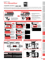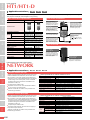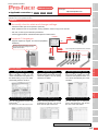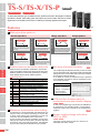
1
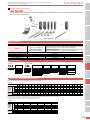
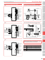
Compact single-axis robots APPLICATION TRANSERVO Single axis TS-S/TS-X/TS-P Robot positioner TS series CE compliance FLIP-X Single-axis robots TS series are positioner type controllers that only performs point trace. No program is needed. Operation is simple. After setting point data, specify the point number and enter a START signal from host controller such as a PLC. Positioning or pushing operation then begins. TS-S PHASER TS-X TS-P 1 Main operation patterns P1 Position SCARA robots YK-XG Moves to the target position relative to the origin point and completes positioning. Moves a specified distance from the current position Current position P1 Moves from the current position just by a distance specified in point data and completes positioning. Changes speed with no deceleration P1 P2 Moves to multiple points in succession. If different speeds were set, then the speeds are changed without decelerating and stopping to continue point-to-point operation. Decelerates and then pushes N P1 CLEAN Pushing starts after decelerating at a distance equal to “Near width (N)” from the target position. 2 Detailed data can be set for each point CONTROLLER INFORMATION Settings such as acceleration, deceleration, zone output range, and position margin zone can be set for each point. Different operations can be easily specified by combining these settings with the above operation patterns. Setting items Setting item Description Specifies operation pattern such as ABS, INC, positioning, push, and point-to-point link. 2 Position Specifies position or distance to move. 3 Speed Specifies maximum speed during operation. 4 Accel. Specifies acceleration during operation. Specifies deceleration during operation 5 Decel. (Percentage of acceleration) Specifies motor current limitation during 6 Push pushing operation. 7 Zone (-) Specifies upper and lower limits of “personal zone” for each point data. 8 Zone (+) Specifies position margin zone where “near 9 Near width width” output should turn on. Specifies next movement destination after positioning 10 Jump or linked destination for point-to-point operation. 11 Flag Specifies stop mode and others. Specifies the waiting time (delay) after 12 Timer positioning completion. 1 Run type Robot positioner Pulse string driver Robot controller iVY Note:Acceleration and deceleration can be set in easy-to-understand percentage (%) units (standard setup) or in SI units (custom setup) which make it easy to calculate the cycle time. 3 Maximum acceleration auto setting Electric gripper Acceleration is a critical parameter that determines how long the robot can continue operating (or service life). In worst cases, setting the acceleration too high may cause the robot to breakdown after a short time. On the TS series, the maximum acceleration is finely set by taking into account the service life span of the motor output and the guide for each robot model and payload. This eliminates any worry about setting the acceleration too high by mistake. Option 396 Output pattern Output turns ON when a specified zone is entered ON OFF P1 Zone for external I/O output can be set for each point. “Near width” output P1 Moves while pushing at a preset push force. Pushing after decelerating YP-X Pick & place robots Pushing operation Pushes at a fixed thrust INC (incremental) operation Speed ABS (absolute) operation XY-X Cartesian robots Moves to a specified coordinate position. Merge operation Zone output Normal operation Merge operation Linear motor single-axis robots Features Specify position margin zone. P1 “Near width” output zone can be set for each point as a position margin zone where “positioning complete” signal is to be output. 4 Full range of monitor functions P.411 The TS-Manager developed exclusively for the TS series not only does data write, edit, backup tasks and parameter settings but also comes loaded with cycle-time, simulator, and monitor functions of all types. A run-distance monitor for maintenance use is provided as a standard unit feature. Design emphasizes easy, user-friendly operation. Main monitor displays · Position · Speed · Current · Load factor · Voltage · Temperature · Input information · Output information 5 LCD monitor showing easy-to understand operation status display TS-X TS-P A main-unit integrated type LCD monitor is available as an optional unit. The operation status, current position, load factor, and/or error contents can be understood at a glance. P. 405 6 Power supply voltage selectable 100V or 200V TS-X TS-P The power supply voltage for the TS-X and TX-P is selectable from 100V or 200V. This function allows monitoring the various data design and operation status of any controller connected via daisy chain from one PC or handy terminal. Compact single-axis robots 7 Daisy chain function TS-S TS-X TS-P APPLICATION TRANSERVO TS-S/TS-X/TS-P Instruction manuals can be downloaded from our company website. Please use the following for more detailed information. http://www.yamaha-motor.co.jp/global/industrial/robot/ FLIP-X Single-axis robots HT1 or PHASER Linear motor single-axis robots TS-Manager Cartesian robots XY-X Up to 16 controllers TS-S TS-X Main power supply DC24V +/-10% maximum Power SCARA robots Name YK-XG Model Overview TS-P AC100V specifications Single phase 100 to 115V +/-10% maximum (50/60Hz) TS-S Controller CONTROLLER INFORMATION TS-X / TS-P TSX I/O NP: NPN PN: PNP CC: CC-Link DN: DeviceNet Driver:Power-supply voltage / Power capacity 105: 100V / 100W more less 110: 100V / 200W 205: 200V / 100W more less 210: 200V / 200W 220: 200V / 400 to 600W Controller TSX: TS-X TSP: TS-P Regenerative unit No entry: None R: With RGT R: With RGU-2 Input/Output Selection NP: NPN PN: PNP CC: CC-Link DN: DeviceNet LCD monitor No entry: None L: With LCD Battery Note1 B:With battery (Absolute model) N:None (Incremental model) Note1. Battery can only be selected for TS-X. (Not provided for TS-P). Robot positioner TS-X / TS-P specification selection table Some specifications are automatically determined by the robot model. TS-X T9H (1) (1) (2) (2) F8 / C8 F8L / F8LH / F10 / F14 / F14H / F17 / F17L / F20 / F20N N15 / N18 / B10 C8L C8LH C10 C14 C14H C17 C17L C20 N15D N18D (1) (1) (1) (1) (2) (2) (3) (3) (3) (3) (4) (4) B14H (5) (5) R5 R10 R20 iVY (1) Regenerative unit is needed if using in a perpendicular position and movement stroke is 700mm or more. (2) Regenerative unit is needed if using in a perpendicular position. (3) Regenerative unit is needed if using in a perpendicular position, using at maximum speeds exceeding 1000mm per second, or if using high leads (40). (4) Regenerative unit is needed if using at maximum speeds exceeding 1000mm per second. (5) Regenerative unit is needed if using at maximum speeds exceeding 1250mm per second. B14 Robot controller T9 Pulse string driver T4LH / T5LH / T6L / C4LH C5LH C6L 105 Power 110 supply voltage / TS-X 205 Current 210 sensor 220 Regenera- No entry (None) tive unit R (RGT) CLEAN TS-S Pick & place robots Ordering method YP-X AC200V specifications Control power supply Single phase 200 to 230V +/-10% maximum (50/60Hz) DC24V +/-10% maximum Operating method I/O point tracing / Remote command / Operation using RS-232C communication Maximum number of controllable axes Single-axis Position detection method Incremental Absolute / Incremental Incremental / Semi-absolute Compact single-axis robot TRANSERVO Single-axis robot FLIP-X Linear motor single-axis robot PHASER Controllable robot Support software for PC TS-Manager TS-P MF7/7D MF15/15D MF20/20D MF30/30D MF75/75D Electric gripper MR12/12D Option 105 Power 110 supply voltage / TS-P 205 Current 210 sensor 220 No entry (None) RegeneraR (RGT) tive unit R (RGU-2) 397 APPLICATION TRANSERVO TS-S/TS-X/TS-P TS-S basic specifications Axis control Points PHASER Linear motor single-axis robots XY-X Cartesian robots SCARA robots YK-XG External input/output FLIP-X Single-axis robots YP-X Pick & place robots General specifications Options Compact single-axis robots Basic specifications Item Model Number of controllable axes Controllable robots Power capacity Dimensions Weight Control power supply Input power supply Motor power supply Control method TS-S Single-axis TRANSERVO series 70 to 110VA W30 × H162 × D82mm Approx. 0.2kg DC24V +/-10% maximum DC24V +/-10% maximum Closed loop vector control method Operating method Operation types Position detection method Resolution Origin search method Points I/O point tracing (Positioning operation by specifying point number) / Remote command Positioning, merge-positioning, push, and jog operations Resolver 20480 P/rev Incremental 255 points (1) Standard setting: Set speed and acceleration in percent of the respective maximum settings. Point type setting (2) Custom setting: Set speed and acceleration in SI units. Point teaching method Manual data input (coordinates input), Teaching, Direct teaching I/O interface Selectable from the following: NPN, PNP, CC-Link, DeviceNet Servo ON (SERVO), reset (RESET), start (START), interlock (/LOCK) origin search (ORG), manual mode Input (MANUAL), jog motion - (JOG-), jog motion + (JOG+), Point number selection (PIN0 to PIN7) Servo status (SRV-S), alarm (/ALM), operation end (END), operation in-progress (BUSY), Output control outputs (OUT0 to 3), Point number output 0 to 7 (POUT0 to POUT7) External communications RS-232C 1CH Safety circuit Emergency stop input, emergency stop contact output (1 system: When the HT1 is used.) Handy terminal HT1, HT1-D (with enable switch) Support software for PC TS-Manager Operating temperature / Operating humidity 0°C to 40°C, 35% to 85%RH (non-condensing) Storage temperature/ Storage humidity -10°C to 65°C, 10% to 85%RH (non-condensing) Atmosphere Indoor location not exposed to direct sunlight. No corrosive , flammable gases, oil mist, or dust particles Anti-vibration All XYZ directions 10 to 57Hz unidirectional amplitude 0.075mm 57 to 150Hz 9.8m/s2 Positioning detection error, power module error, temperature abnormality, overload, overvoltage, low voltage, Protective functions gross position error CLEAN TS-X / TS-P basic specifications Model Basic specifications Axis control Points Pulse string driver Robot controller iVY External input/output Robot positioner Electric gripper Option General specifications Options CONTROLLER INFORMATION Item 398 Driver model Number of controllable axes Controllable robots Power capacity Dimensions Weight Control power supply Input power supply Motor power supply Control method Operating method Operation types Position detection method Resolution Origin search method Number of points TS-X / TS-P 100V AC input 200V AC input TS-X105 / TS-P105 TS-X110 / TS-P110 TS-X205 / TS-P205 TS-X210 / TS-P210 TS-X220 / TS-P220 Single-axis TS-X: Single-axis robot FLIP-X series TS-P: Linear motor single-axis robot PHASER series 1400VA 400VA 600VA 400VA 600VA W58 × H162 × D131mm W70 × H162 × D131mm Approx. 0.9kg Approx. 1.1kg Single phase AC100 to 115V +/-10% 50/60Hz Single phase AC200 to 230V +/-10% 50/60Hz Single phase AC100 to 115V +/-10% 50/60Hz Single phase AC200 to 230V +/-10% 50/60Hz Closed loop vector control method I/O point tracing (Positioning operation by specifying point number) / Remote command Positioning, merge-positioning, push, and jog operations TS-X: Resolver with multi-rotation absolute function TS-P: Magnetic type linear scale TS-X: 16384 P/rev TS-P: 1μm TS-X: Absolute / Incremental TS-P: Incremental / Semi-absolute 255 points (1) Standard setting: Set speed and acceleration in percent of the respective maximum settings. Point type setting (2) Custom setting: Set speed and acceleration in SI units. Point teaching method Manual data input (coordinates input) , Teaching, Direct teaching I/O interface Selectable from the following: NPN, PNP, CC-Link, DeviceNet Servo ON (SERVO), reset (RESET), start (START), interlock (/LOCK) origin search (ORG), manual mode Input (MANUAL), jog motion - (JOG-), jog motion + (JOG+), Point number selection (PIN0 to PIN7) Servo status (SRV-S), alarm (/ALM), operation end (END), operation in-progress (BUSY), Output control outputs (OUT0 to 3), Point number output 0 to 7 (POUT0 to POUT7) External communications RS-232C 1CH Power supply for brake DC24V +/-10% 300mA (prepared by the customer) Emergency stop input, main power input ready output, emergency stop contact output (1 system: When the HT1 is used.) Safety circuit Handy terminal HT1, HT1-D (with enable switch) Support software for PC TS-Manager Operating temperature / Operating humidity 0°C to 40°C, 35% to 85%RH (non-condensing) Storage temperature / Storage humidity -10°C to 65°C, 10% to 85%RH (non-condensing) Atmosphere Indoor location not exposed to direct sunlight. No corrosive , flammable gases, oil mist, or dust particles Anti-vibration All XYZ directions 10 to 57Hz unidirectional amplitude 0.075mm 57 to 150Hz 9.8m/s2 Positioning detection error, power module error, temperature abnormality, overload, overvoltage, low voltage, Protective functions gross position error Protective structure IP20 TS-S part names TS-S / TS-X / TS-P dimensions Status indicator lamps (PWR, ERR) The controller status is indicated by LED lamps. 5 TS-S (70) 30 82 Compact single-axis robots Controller Communication connector 2 (COM2) Connector for the daisy-chain connection cable. ϕ4.5 25 152 162 FLIP-X Robot I/O connector (ROB I/O) Dedicated connector for robot I/O signals such as position signals and origin sensor signals, etc. Single-axis robots 152 Serial No. Communication connector 1 (COM1) Connector for connection to HT1 or a personal computer. R 4.5 (90) 58 PHASER TS-X/TS-P (105/110/205/210) 4 131 ϕ5.4 53 152 162 167 XY-X Cartesian robots TS-X / TS-P part names (8) 5 R 5.4 SCARA robots EXT connector YK-XG Power supply connector Serial No. Connector for main power and control power input. Unit's top cover in Status indicator lamps an open condition Controller (PWR, ERR) The controller status is indicated by LED lamps. Rating nameplate (on side face of unit body) Communication connector 1 (COM1) Connector for connection to HT1 or a personal computer. Linear motor single-axis robots Rating nameplate (on side face of unit body) Power supply connector Connector for main power and control power input. 5 5 I/O connector (I/O) Selectable at time of purchase as: NPN,PNP, CC-LINK or DeviceNet. 4 TS-X/TS-P (220) Robot I/O connector (ROB I/O) (90) ϕ5.4 53 162 167 131 152 70 58 Pick & place robots CLEAN Dedicated connector for robot I/O signals such as position signals and origin sensor signals, etc. Motor connector (MOTOR) Connector for the servo motor's power line connection. I/O connector (I/O) Connector type is selected NPN, PNP, or CC-LINK when purchased. Regenerative unit connector (RGEN) Connector for the regenerative unit connection. YP-X 5 R EXT connector (8) Communication connector 2 (COM2) Connector for the daisy-chain or LCD monitor connection. Absolute battery connector (BAT) Connector for the absolute battery connection. (only for TS-X) EXT connector (bottom face of unit body) Connector for brake power input and external safety circuit inputs/outputs. 5.4 •Install the TS-S/TS-X/TS-P inside the control panel. TS-S TS-X/TS-P 20mm or more •Install the TS-S/TS-X/TS-P on a vertical wall. •Install the TS-S/TS-X/TS-P in a well ventilated location, with space on all sides of the TS-S/TS-X/TS-P (See fig. at right.). 20mm or more PWR SRV COM2 PWR ERR COM1 L ROB I/O COM1 N 200V L1 •Ambient temperature : 0 to 40˚C I/O : 35 to 85% RH (no condensation) 10mm or more ES1 ES2 ESMP24V CP24V 0V N1 20mm or more 10mm or more ROB I/O CHARGE MOTOR 20mm or more I/O RGEN Regenerative unit RGU-2 Regenerative unit RGT Dimensions 2 120 157 5.5 250 265 290 ϕ5.5 iVY 162 152 142 15 30 40 16 Robot controller 5 Dimensions Pulse string driver Regenerative unit RGT/RGU-2 Robot positioner 20mm or more 20mm or more CONTROLLER INFORMATION Installation conditions •Ambient humidity APPLICATION TRANSERVO TS-S/TS-X/TS-P Instruction manuals can be downloaded from our company website. Please use the following for more detailed information. http://www.yamaha-motor.co.jp/global/industrial/robot/ RGEN R2.75 RGT Note. Always leave an empty space (gap of about 20mm) between this unit and the adjacent controller. Also, always use the dedicated cable when connecting the controller. RGU-2 TS-P KCA-M4107-2A (Including accessory) W40 × H250 × D157mm 0.9kg Approx. 380V or more Approx. 360V or less Cable for connection with controller (300mm) Note. Always leave an empty space (gap of about 20mm) between this unit and the adjacent controller. Also, always use the dedicated cable when connecting the controller. Option KCA-M4107-0A W30 × H142 × D118mm (Not including installation stay) 470g Approx. 420V or more Approx. 380V or less Cable for connection with controller (300mm) Item Model Dimensions Weight Regenerative voltage Regenerative stop voltage Accessory Electric gripper Basic specifications Basic specifications Item Model Dimensions Weight Regenerative voltage Regenerative stop voltage Accessory 399 APPLICATION TRANSERVO TS-S/TS-X/TS-P Data overview Compact single-axis robots Point data and parameter data settings must be specified in order to operate a robot from a TS series controller. Point data FLIP-X Single-axis robots The point data used in positioning operations includes items such as the “RUN type”, “Position”, and “Speed”, etc. Up to 255 points (P1 to P255) can be registered. There are two point data setting types: “Standard setting” type that automatically defines optimal positioning simply by specifying the payload and “Custom setting” type that allows setting the speed (mm/s) and acceleration (m/s2) in SI units. Select the desired setting type according to the application. Parameter data PHASER Linear motor single-axis robots Parameter data is divided into the following categories: “RUN parameters”, “I/O parameters”, “option parameters”, and “servo parameters”. Data structure Point data Data XY-X Cartesian robots 1 2 3 4 5 6 SCARA robots YK-XG P1 to P255 7 Zone (-) RUN type 8 Zone (+) Position 9 Near width Speed 10 Jump Accel. 11 Flag Decel. 12 Timer Push Parameter data K1 to K20 RUN parameter YP-X Pick & place robots K21 to K39 I/O parameter K80 to K99 Option parameter CLEAN K40 to K79, K100 to ... Servo parameter Sets the point data to be used in positioning. Select the desiredsetting type (“standard setting” or “custom setting”) according to the application. (1) Standard setting Optimum positioning is provided simply by specifying the payload. (2) Custom setting Speed and acceleration can be set in SI units. Specifies parameter settings related to positioning and return to-origin operations. Specifies parameter settings related to terminal assignments and I/O function selection. Specifies parameter settings related to options such as CC-Link, etc. Specifies parameter settings specified to the connected robot. These parameters are specified during initial processing. CONTROLLER INFORMATION Point data Point data item list Robot positioner Pulse string driver Robot controller 1 2 3 4 5 6 7 8 9 10 11 12 Item RUN type Position Speed Accel. Decel. Push Zone (-) Zone (+) Near width Jump Flag Timer P1 to P255 Description Specifies the positioning operation pattern. Specifies the positioning target position or movement amount. Specifies the positioning speed. Specifies the positioning acceleration. Specifies the positioning deceleration (as a percentage of the acceleration). Specifies the electrical current limit value for “Push” operations. Specifies the “personal zone” output range. Specifies the “near width” zone (distance tolerance relative to target position). Specifies the next movement destination, or the next merge operation merge destination point No. following positioning completion. Specifies other information related to the positioning operation. Specifies the waiting time (delay) after positioning completion. “Standard setting” and “custom setting” iVY There are 2 setting types for point data (“standard setting” or “custom setting”). Select the desired setting type according to the application. The maximum number of setting points for both setting types is 255 points (P1 to P255). Setting Type Electric gripper Standard setting Custom setting Option 400 Description Optimum positioning is provided simply by specifying the payload. This setting type is well-suited to assembly and transport applications. Allows changing the speed and acceleration in SI units so the desired positioning operation can be set. This setting type is suited for machining and inspection systems. Emergency stop circuit example TS-S TS-S (power connector and host unit connection example) Compact single-axis robots NPN type input / output wiring diagram Controller I/O(NPN) +COM Power supply 0V Frame ground 0V FG Operation-in-progress End-of-operation Alarm Servo status PIN0 Handy Terminal External "emergency stop" External 24V ES1 PIN 0 to 7 Point No. selection ES2 CP24V 0V Internal GND External 0V External 0V SCARA robots YK-XG TS-X MP24V Cartesian robots I/O power - common -COM ES Status ES- JOG movement (+) JOG movement (-) MANUAL mode Return-to-origin Interlock Start Reset Servo ON XY-X PIN7 JOG+ JOGMANUAL ORG /LOCK START RESET SERVO PHASER ES1 ES2 ESMP24V CP24V Control outputs OUT 0 to 3 OUT3 BUSY END /ALM SERVO-S Linear motor single-axis robots “Emergency stop” contact 1 “Emergency stop” contact 2 “Emergency stop” READY signal Main power input Control power input 24V DC FLIP-X Point No. outputs POUT 0 to 7 POUT7 OUT0 Power connector Controller COM1 Single-axis robots POUT0 DC24V I/O power + common APPLICATION TRANSERVO TS-S/TS-X/TS-P Instruction manuals can be downloaded from our company website. Please use the following for more detailed information. http://www.yamaha-motor.co.jp/global/industrial/robot/ TS-X / TS-P (EXT connector and host unit connection example) Controller Controller Note. When using a brake-equipped robot. PIN 0 to 7 Point No. selection Internal power NO NC JOG movement (+) JOG movement (-) MANUAL mode Return-to-origin Interlock Start Reset Servo ON 1 2 3 4 5 6 7 8 External 0V MPRDY2 External “emergency stop” ES- RY ES2 PIN7 JOG+ JOGMANUAL ORG /LOCK START RESET SERVO Internal GND L MPRDY1 DC24V PIN0 N ES1 DC24V Operation-in-progress End-of-operation Alarm Servo status 0V ES+ ES1 ES2 MPRDY2 MPRDY1 ES+24V 0V OUT3 BUSY END /ALM SERVO-S N1 EXT connector External 24V I/O power - common -COM Note. Always connect a surge absorber unit to the coil on the electromagnetic contactor. I/O(NPN) +COM POUT0 Main power input L N EXT Main power input READY output contact “Emergency stop” READY signal DC24V PIN0 PIN7 JOG+ JOGMANUAL ORG /LOCK START RESET SERVO -COM Control outputs OUT 0 to 3 Operation-in-progress End-of-operation Alarm Servo status PIN 0 to 7 Point No. selection JOG movement (+) JOG movement (-) MANUAL mode Return-to-origin Interlock Start Reset Servo ON I/O Specifications Item Description Input 16 points, 24VDC +/-10%, 5.1mA/point, positive common Output 16 points, 24VDC +/-10%, 50mA/point, sink type Input 16 points, 24VDC +/-10%, 5.5mA/point, minus common PNP Output 16 points, 24VDC +/-10%, 50mA/point, source type CC-Link CC-Link Ver.1.10 compatible, Remote station device (1 node) DeviceNet DeviceNet Slave 1 node NPN Electric gripper ES+ ES1 ES2 MPRDY2 MPRDY1 ES+24V 0V OUT3 BUSY END /ALM SRV-S Point No. outputs POUT 0 to 7 iVY Internal power for “emergency stop” input “Emergency stop” contact 1 “Emergency stop” contact 2 POUT7 OUT0 DC24V I/O power + common Robot controller Control power input Pulse string driver Installing an external safety circuit will satisfy safety category class 4 standards. See P.483 for more information. Controller L1 N1 Robot positioner TS-P CONTROLLER INFORMATION Note. Mechanical brake power input EXT ES Status L1 Control outputs OUT 0 to 3 CLEAN L N Main power input Internal power for “emergency stop” input “Emergency stop” contact 1 “Emergency stop” contact 2 Main power input READY output contact “Emergency stop” READY signal Handy Terminal ES+ Control power input Point No. outputs POUT 0 to 7 POUT7 OUT0 L1 N1 DC24V I/O power + common +24V POUT0 YP-X I/O(NPN) +COM Pick & place robots COM1 I/O power - common Option 401 APPLICATION TRANSERVO TS-S/TS-X/TS-P I/O signals (NPN / PNP) Compact single-axis robots No. Signal Name A1 I/O power input, positive common (24VDC +/-10%) +COM A2 Single-axis robots FLIP-X A3 Description NC No. Signal Name B1 POUT0 B2 POUT1 B3 POUT2 Description No connection A4 NC B4 POUT3 A5 PIN0 B5 POUT4 A6 PIN1 B6 POUT5 A7 PIN2 B7 POUT6 A8 PIN3 B8 POUT7 PHASER Linear motor single-axis robots Outputs Point No. outputs Point No. select SCARA robots YK-XG YP-X Pick & place robots CLEAN PIN4 B9 OUT0 A10 PIN5 B10 OUT1 A11 PIN6 B11 OUT2 A12 PIN7 B12 OUT3 A13 JOG+ JOG movement (+ direction) B13 BUSY Operation-in-progress A14 JOG- JOG movement (- direction) B14 END Operation-end A15 MANUAL MANUAL mode B15 /ALM Alarm A16 ORG Return-to-origin B16 SRV-S A17 /LOCK Interlock B17 NC A18 START Start B18 NC A19 RESET Reset B19 A20 SERVO Servo ON B20 Inputs XY-X Cartesian robots OUT0 to OUT3 assignments include: • Zone output • Personal zone output • MANUAL mode status • Return-to-origin end status • NEAR output • Movement-in-progress • Push status • Warning output A9 Servo status No connection CONTROLLER INFORMATION -COM I/O power input, negative common (0V) NPN type I/O circuit details PNP type I/O circuit details Input circuit Input circuit +COM +COM DC24V 4.7kΩ Input Input Internal circuit Logic circuit Robot positioner DC24V 4.7kΩ -COM -COM Type : DC input (minus common type) Photo-coupler isolation format Load : 24VDC +/- 10%, 5.5mA ON voltage : 19.6Vmin (4.5mA) OFF voltage : 4.9Vmax (1.1mA) Pulse string driver Type : DC input (plus common type) Photo-coupler isolation format Load : 24VDC +/- 10%, 5.1mA OFF voltage : 19.6Vmin (1.0mA) ON voltage : 4.9Vmax (4.0mA) Robot controller Output circuit Output circuit +COM iVY +COM Output Electric gripper Internal circuit Internal circuit Logic circuit Logic circuit Load DC24V Internal circuit Logic circuit Output DC24V -COM -COM Option Type : NPN open collector output (Minus common type) Photo-coupler isolation format Load : 24VDC, 50mA/point 402 Type : PNP open collector output (Plus common type) Photo-coupler isolation format Load : 24VDC, 50mA/point Load Accessories and part options Power connector Power connector (AC200V specifications) TS-X TS-X TS-SD TS-P TS-P KCC-M4421-00 Model Model I/O cables (2m) PHASER Dummy connector KAS-M5382-00 Linear motor single-axis robots EXT connector KCA-M5382-00 FLIP-X TS-S Single-axis robots Model Power connector (AC100V specifications) Compact single-axis robots Standard accessories APPLICATION TRANSERVO TS-S/TS-X/TS-P Instruction manuals can be downloaded from our company website. Please use the following for more detailed information. http://www.yamaha-motor.co.jp/global/industrial/robot/ For braking power and safety circuit connections. TS-S TS-X TS-X TS-P TS-P TS-P XY-X Cartesian robots TS-S TS-X Model KCA-M5370-00 Model KCA-M5163-00 Model KCA-M4421-20 Absolute battery SCARA robots YK-XG Absolute battery basic specifications TS-X Note. The absolute battery is subject to wear and requires replacement. If trouble occurs with the memory then remaining battery life is low so replace the absolute battery. The battery replacement period depends on usage conditions. But generally you should replace the battery after about 1 year counting the total time after connecting to the controller and left without turning on the power. CLEAN Options Handy terminal HT1 / HT1-D Support software TS-Manager Has graphic LCD display with backlight for easy viewing. 6XSSRUW6RIWZDUH TS-Manager TS-X TS-P 760DQDJHU9HU 0DQXDO9HU 86%'ULYHU9HU <$0$+$5RERW6XSSRUW6RIWZDUH760DQDJHU 760DQDJHULQVWDOODWLRQGLVN 760DQDJHU6RIWZDUH 760DQDJHU8VHU¶V0DQXDO>3')'$7$@ 'HYLFH'ULYHUIRU86%6HULDO&DEOH &RS\ULJKW&<$0$+$02725&2/7' $OOULJKWVUHVHUYHG <$0$+$02725&2/7' Communication cable for TS-Manager. Select from USB cable or D-sub cable. TS-S TS-X TS-P TS-SD HT1-D USB TS-Monitor (LCD monitor) TS-P KCA-M5119-00 KCA-M5119-10 Daisy chain coupler cable TS-S TS-Manager environment Microsoft Windows 2000/ XP/Windows Vista/7 Exceeding the environment CPU recommended by the OS being used Exceeding the environment Memory recommended by the OS being used Vacant capacity of Hard disk more than 20MB in the installation destination drive Communication port Serial (RS-232C), USB Applicable controllers TS-S / TS-X / TS-P / TS-SD TS-X OS Note. Windows is the registered trademark of US Microsoft Corporation in U.S.A. and other countries. P.411 TS-P TS-SD Model KCA-M532L-00 CC-Link connector Connector Jump socket Note. Model Connector Jump socket Option P.405 Note. USB driver for communication cable can also be downloaded from our website (driver supports VIP+, POPCOM, and TS-Manager). Electric gripper For TS-X For TS-P USB type (5m) KCA-M538F-A0 D-Sub type (5m) KCA-M538F-01 iVY TS-X Model Robot controller A liquid crystal display is integrated into this unit. It allows checking each operating state, current position, electrical current and voltage values, etc. KCA-M4966-00 Pulse string driver P.406 Model D-Sub Robot positioner HT1 HT1-D 3.5m KCA-M5110-0E KCA-M5110-1E Model 10m KCA-M5110-6E KCA-M5110-7E Enable switch – 3-position CE marking Not supported Applicable Model CONTROLLER INFORMATION TS-S HT1 Data cables Besides data writing, editing and backup functions, the TS-Manager also offers cycle time simulation and various types of monitor functions. Pick & place robots Dimensions Weight KCA-M53G0-10 Absolute battery KCA-M53G0-10 Lithium metallic battery 3.6V / 1,650mAh About 1 year (in state with no power applied) ϕ18 × L50mm 24g YP-X Model Item Model Battery type Battery capacity Data holding time KCA-M4872-00 KCA-M4873-00 Note. This is a single connector type. (Insert two connectors into a branching socket.) 403 APPLICATION TRANSERVO TS-S/TS-X/TS-P Options Compact single-axis robots DIN rail mounting bracket KCC-M499A-00 TS-S FLIP-X Single-axis robots 82 81 162 PHASER Linear motor single-axis robots For TS-S KCC-M499A-00 30 (81) Model 12.5 XY-X Cartesian robots SCARA robots YK-XG TS-X KCA-M499A-00 YP-X 131 167 (86) For TS-X / TS-P KCA-M499A-00 58 81 CONTROLLER INFORMATION TS-X(P)220 TS-X(P)205, TS-X(P)210 TS-X(P)105, TS-X(P)110 25.5 70 58 167 (86) 131 81 (35) CLEAN Model 25.5 (35) Pick & place robots TS-P Robot positioner Pulse string driver TS-X KCA-M499A-10 TS-P Robot controller 120 For TS-X / TS-P with RGT KCA-M499A-10 (81) iVY Model 81 162 Electric gripper Option 404 15 30 TS-Monitor TS-X TS-P FLIP-X The TS Monitor Advantage Before installing TS Monitor After installing TS-Monitor Shows basic info / 3 $ 326PP Simple status display : ON / : OFF Run mode (1&2'(5(5525 Current position '%*6 6 2 ( / 3 $ Alarm occurs. Error or warning alarm number Alarm name 326PP Shows I/O status I/O screen Displays input/output bit states. Simple status display Display S E P O L A Meaning Servo status Emergency stop Main power failure Return-to-origin completion status Interlock status Alarm Run mode Display NRM MON DBG ,2 ,1 287 Meaning Normal mode Monitor mode Debug mode 21ࠈ2)) ) ( ' & % $ 2 ) ( ' & % $ 2 Input signal status * Displays the status of input bit 0 to 15. Output signal status * Displays the status of output bit 0 to 15. Bit signal correspondence table STATUS Shows status info screen Info such as error status or movement status is all at a glance. Status display Controller name Controller software version Robot name Point type CHECK Shows operating status screen Displays total drive distance (helpful for preventive maintenance). 21ࠈ2)) 67$786 6596(6723 25*6(13%/. 7/0625*6 029(:$51 RUN screen Internal voltage of controller Temperature inside controller Total startup time of controller (Day : Hour : Minute) Total movement distance of robot Run type 326PP Robot current position Run point 63'PPV Robot operation speed /2$'㸚 Load rate $%60(5*( ڻ3 Display HOLD ABS INC ABS MERGE INC MERGE ABS PUSH INC PUSH ABS->PUSH INC->PUSH ORG Meaning Servo is off or robot is stopping. ABS INC ABS merge operation INC merge operation ABS push operation INC push operation ABS deceleration push operation INC deceleration push operation Return-to-origin Dimensions Robot positioner TS-X/TS-P (105/110/205/210) with TS-Monitor button button I/O screen STATUS screen 70 (83.5) ϕ5.4 53 137.5 162 167 58 Option KCA-M5119-00 KCA-M5119-10 W40.546 × H25.63mm Graphic monochrome LCD Blue and red, 2-color LCD 5 steps 128 × 64 dots 4 Electric gripper TS-X Model TS-P Effective display size Screen display Backlight Contrast adjustment Number of display dots 5.4 TS-X/TS-P (220) with TS-Monitor button TS-Monitor basic specifications 152 5 EXT connector iVY button R button 152 button 162 RUN screen R EXT connector 5.4 5 button ϕ5.4 53 137.5 Robot controller Alarm occurs. MAIN screen button button (83.5) (8) button 58 (8) button (or transits after a certain period of time has elapsed.) 4 CHECK screen 167 INFORMATION screen button Pulse string driver Startup screen Run type Info includes position, speed, load factors and run type. Screen transition Transits after a certain period of time has elapsed. Meaning Servo status Origin sensor Push status Move status Emergency stop Main power failure Return-to-origin completion status Warning output Shows operation status and data 581 &+(&. 92/79 7(03Υ 7,0( ',67NP Status display : ON, : OFF Display SRV-S ORGSEN TLM-S MOVE E-STOP P-BLK ORG-S WARN CONTROLLER INFORMATION ,1)250$7,21 &21776;$ 9(5 52%27) 37<3&86720 CLEAN 8 9 A B C D E F JOG+ SERVO RESET START /LOCK ORG MANUAL JOG0 1 2 3 4 5 6 7 PIN0 PIN1 PIN2 PIN3 PIN4 PIN5 PIN6 PIN7 8 9 A B C D E F BUSY OUT3 OUT2 OUT1 OUT0 END SRV-S /ALM OUT 0 1 2 3 4 5 6 7 POUT7 POUT6 POUT5 POUT4 POUT3 POUT2 POUT1 POUT0 IN INFORMATION Shows machine info screen Displays the connected robot and version. YP-X '%*6 2 ( Red backlit display appears during alarms. 0$,176021,725 Desired character string specified by the user. 6 Easy to see error messages in case of alarm Pick & place robots 0$,176021,725 MAIN screen Error Displays optional name or character string. SCARA robots MAIN screen YK-XG Features Cartesian robots Backlit display is bright and easy to read even on dark panels. XY-X Display shows total operating time, so scheduling maintenance periods is easy. Without a handy terminal “HT1” and PC software “TS-Manager”, the operator does not know what caused the alarm and it takes a time to find out the cause. PHASER During errors the backlit display turns red and operator can see what error occurred on what controller at a glance. Linear motor single-axis robots Operator instantly knows various information without hooking to a handy terminal or PC. in normal operation Single-axis robots Integrated into the controller unit, the TS-monitor needs no connections to the handy terminal or PC and checks operation status, current position, error information, etc. The TS-monitor even allows the operator on the scene or service personnel to easily check the controller status. Total operating time is also displayed which is convenient to schedule maintenance periods. Compact single-axis robots Applicable controllers APPLICATION TRANSERVO LCD Monitor option 405 APPLICATION TRANSERVO Handy terminal HT1/HT1-D Compact single-axis robots Applicable controllers TS-S TS-X TS-P This Handy Terminal is a device that can perform any operation such as robot manual operation, point data edit, teaching, and parameter setting, etc. Has graphic LCD display with backlight for easy viewing. FLIP-X Single-axis robots HT1 / HT1-D basic specifications Name HT1 Part names and function Strap holder HT1-D Attaching a short strap or necklace strap here prevents dropping the HT1 while operating it or installing it onto equipment. PHASER Linear motor single-axis robots External view Emergency stop button Pressing this button during operation immediately stops robot movement. To release this button, turn it clockwise. Releasing this button also cancels emergency stop. LCD screen Applicable controllers XY-X Cartesian robots SCARA robots YK-XG YP-X Pick & place robots CLEAN TS-S / TS-X / TS-P KCA-M5110-0J(3.5m) KCA-M5110-1J(3.5m) Japanese specifications KCA-M5110-6J(10m) KCA-M5110-7J(10m) Model KCA-M5110-0E(3.5m) KCA-M5110-1E(3.5m) English specifications KCA-M5110-6E(10m) KCA-M5110-7E(10m) Dot matrix monochrome display (with Display backlighting) 32 characters × 10 lines Operation keys Mechanical switch Normally closed contact point Emergency stop button (with lock function) Enable switch 3-position 15 pin D-sub Safety connector connector (male) CE marking Not supported Applicable Operating temperature 0°C to 40°C Operating humidity 35% to 85%RH (non-condensing) W88 × H191 × D45mm Dimensions (Emergency stop button not included.) 260g 300g Weight (not including cable) (not including cable) Cable length 3.5m / 10m This is a liquid crystal display (LCD) screen with 32 characters × 10 lines (pixel display), showing the operation menus and various types of information. Data edit keys Run/stop keys Use these keys to select menus and edit various data. Use these keys to operate the robot for teaching or positioning, or to stop operation. The and keys are also provided to move the robot in jog mode. Connector cable This cable connects to the controller. One end of this cable is terminated with an 8-pin MD connector (male). Plug this cable into the COM1 connector on the controller front panel. HT1-D rear side Enable switch (only on HT1-D) This switch is effective for use with remote safety circuits. This switch cuts off the circuit when pressed or released but allows circuit operation when in the middle position. Safety connector (only on HT1-D) Use with remote safety circuits triggered by the emergency stop button or enable switch. CONTROLLER INFORMATION Field network system with minimal wiring NETWORK Applicable controllers TS-S TS-X TS-P Network modules CC-Link Option unit with networking functions that can be incorporated in YAMAHA robot controllers, TS-S / TS-X / TS-P. Robot positioner As connection of the robot system and the sequencer requires only one (4-wire) dedicated cable, it is possible to save wiring of the entire system, which contributes to efficient wiring work, reduction of installation and maintenance costs, etc. Pulse string driver 16 input/outputs usable as I/O. Operation occurs as a CC-Link remote device station, on a one-unit to one-station basis. Robot controller Remote commands can read or write point data and load each type of status. Basic specifications for network modules CC-Link Item Applicable controllers Version supporting CC-Link Remote node type Number of occupied nodes Node number setting Communication speed setting No. of CC-Link inputs/outputs Shortest distance between nodesNote1 Overall extension distanceNote1 Monitor LED Network modules CC-Link TS-S / TS-X / TS-P Ver. 1.10 Remote device node 1 node 1 to 64 10Mbps, 5Mbps, 2.5Mbps, 625Kbps, 156Kbps Input 16 points , Output 16 points 0.2m or more 100m/10Mbps, 160m/5Mbps, 400m/2.5Mbps, 900m/625Kbps, 1200m/156Kbps L RUN, L ERR, SD, RD Note 1. These values apply when a cable that supports CC-Link Ver.1.10 is used. Network modules DeviceNet iVY Option unit with networking functions that can be incorporated in YAMAHA robot controllers, TS-S / TS-X / TS-P. Electric gripper As connection of the robot system and the sequencer requires only one (4-wire) dedicated cable, it is possible to reduce wiring of the entire system, which contributes to efficient wiring work, reduction of installation and maintenance costs, etc. 16 input/outputs usable as I/O. Option Operate as slave stations, with each unit occupying 6 input and 6 output channels. Remote commands can read or write point data and load each type of status. 406 Basic specifications for network modules DeviceNet Item Applicable controllers Applicable DeviceNet specifications Device type Number of occupied CH MAC ID setting Communication speed setting DeviceNet inputs/outputs Overall extension distance Network Branch length length Overall branch length Monitor LED Network modules DeviceNet TS-S / TS-X / TS-P Volume 1 Release2.0/Volume 2 Release2.0 Generic Device (device number 0) Input 6ch, Output 6ch 0 to 63 500Kbps, 250Kbps, 125Kbps Input 16 points, Output 16 points 100m/500Kbps, 250m/250Kbps, 500m/125Kbps 6m or less 39m or less/500Kbps, 78m or less/250Kbps, 156m or less/125Kbps Module, Network GP4000 Series Free download of the program file from the Pro-face home page http://www.proface.com TS-S TS-X TS-P Connecting GP4000 Series made by Pro-face to Robot Positioner, TS-S,TS-X,TS-P enables you to use a lot of functions as well as basic operations on Touch Operator Interface. FLIP-X Single-axis robots Features Compact single-axis robots Applicable controllers APPLICATION TRANSERVO Touch operator interface 1 Can easily check a state and change settings. • Check the status (the current position, speed etc) Linear motor single-axis robots PHASER • Basic operations such as Jog operation, inching operation, return to origin, error reset etc. • Set, edit, or back up point data and parameters • Check triggered alarms and detailed descriptions of alarm history Server XY-X 2 Supports 3 languages Cartesian robots Pro-face GP4000 Series • Supports Japanese, English, and Chinese (simplified, traditional) LAN SCARA robots Up to 16 single-axis robot positioners can be connected. YK-XG Without opening the control panel, you can check the status and change the settings on Touch Operator Interface alone. RS-232C YP-X Pick & place robots RS-422 Control Device CLEAN I/O Monitor Screen Information Monitor Screen When a problem occurs, you can check the detailed descriptions of the alarm history, so you can understand easily what the cause is. Displays both general I/O and dedicated I/O together. You can quickly check the I/O status. The screen can display the robot status and the operation status. You can check immediately the robot condition. Position Data Editing Screen Parameter Editing Screen Connecting Selection Screen You can edit and back up point data (255 points).Note While checking parameters of robot positioners in the list, you can set them with the pull-down menu. You can connect up to 16 robot positioners simultaneously with GP-Pro EX Ver.3.0 multi-axis feature. Robot positioner Diagnostic Screen CONTROLLER INFORMATION Screen details Pulse string driver Robot controller Note. Settings for it and a USB storage required. iVY Electric gripper Option Contact; Pro-face TEL:06-6613-1101 FAX:06-6613-5888 407