1
ROBOT DRIVER FOR TRANSERVO
TS-SD
User s Manual
EPM4127101
Ver. 1.01
E118
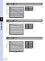
CONTENTS
TS-SD
User’s Manual
Important information before reading this manual
Introduction
i
Main functions
i
About this manual
ii
Safety alert symbols and signal words
iii
CE marking
iv
1. Safety standard
iv
2. Safety measures
iv
3. EMC countermeasure example
v
Safety cautions
vi
Warranty
ix
Chapter 1 Overview
1. Unpacking check
1-1
2 .Part names and functions
1-1
3. System configuration
1-2
4. Installation and operation sequence
1-3
Chapter 2 Installation and wiring
1. Installation method
2-1
2 .Installation conditions
2-2
3. Power supply connection
2-3
4. Connecting the robot
2-5
5. Connecting the I/O connector
2-6
5.1 Connecting the I/O cable (open collector specifications)
2-7
5.2 Connecting the I/O cable (line driver specifications)
2-9
6. Connecting the communication unit
2-11
T-1
CONTENTS
TS-SD
User’s Manual
7. Configuring an emergency stop circuit
2-12
Chapter 3 I/O signal functions
1. I/O specifications
3-1
2 .Open collector specifications
3-2
2.1 I/O signal table
3-2
2.2 I/O signal list
3-2
2.3 Input signal details
3-3
2.3.1 Command pulse input and command direction input (OPC, PULS2, DIR2)
2.3.2 I/O inputs
2.4 Output signal details
3. Line driver specifications
3.1 I/O signal table
3-3
3-5
3-6
3-7
3-7
3.2 I/O signal list
3-7
3.3 Input signal details
3-8
3.3.1 Command pulse input and command direction input (PULS1, PULS2, DIR1, DIR2)
3.3.2 I/O inputs
3.4 Output signal details
3-8
3-10
3-11
Chapter 4 Data setting
1. Data overview
4-1
2 .Parameter data
4-2
2.1 Parameter list
4-2
2.1.1 RUN parameters
2.1.2 I/O parameters
4-2
2.1.3 Option parameters
4-3
2.1.4 Servo parameters
4-3
2.2 Parameter details
4-3
2.2.1 RUN parameters
4-3
2.2.2 I/O parameters
4-4
2.2.3 Option parameters
4-5
2.2.4 Servo parameters
4-6
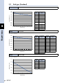
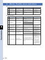
3. Reference graphs and tables of speed and acceleration settings using payload and stroke
3.1 Slider type
T-2
4-2
4-7
4-7
3.2 Rod type (Standard)
4-14
3.3 Rod type (With support guide)
4-23
CONTENTS
TS-SD
User’s Manual
Chapter 5 Operation
1. Operation procedure
5-1
1.1 Overall operation timing chart
5-1
1.2 Alarm occurrence and clearing
5-2
2 .Origin search (return-to-origin)
5-3
2.1 Origin point detection method
5-3
2.2 Machine reference
5-3
3. Soft limit function (only for JOG operation from TS-Manager)
5-4
4. LED status indicators
5-5
Chapter 6 Troubleshooting
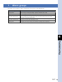
1. Alarm groups
6-1
2 .Alarm recording function
6-2
3. Alarm list
6-3
4. Alarms: Possible causes and actions 6-4
5. Troubleshooting
6-7
Chapter 7 Specifications
1. TS-SD specifications
7-1
1.1 Basic specifications
7-1
1.2 Dimensional outlines
7-2
T-3
Important information before reading this manual
Contents
Introduction
i
Main functions
i
About this manual
ii
Safety alert symbols and signal words
iii
CE marking
iv
1. Safety standard
iv
2. Safety measures
iv
3. EMC countermeasure example
v
Safety cautions
vi
Warranty
ix
Introduction
Main functions
Function
Explanation
Pulse train operation
The TS-SD is applicable to either the open collector methods or line driver methods according to the signal
connections. So, select appropriate specifications suitable for the host unit.
Origin search
Performs an origin search (return-to-origin) simply by entering a return-to-origin command.
JOG operation
Robot JOG operation can be performed from the PC support software (TS-Manager).
Output function
The following statuses can be output to the host unit.
Origin return completion status, servo status, positioning completion, alarm
Alarm history
Saves up to 50 of the most recent alarms. Additionally, the alarm occurrence status (position and input/
output information, etc.) can be read.
Daisy chain
Up to 16 TS-SD drivers can be connected in a daisy chain.
Support tools
■ PC support software TS-Manager (Compliant version is 1.3.0 or higher.)
This support software fully utilizes the operability of Windows to efficiently perform the JOG operation,
return-to-origin, parameter setting, debugging, maintenance, and management. A trace function that
graphically displays the internal information about the TS-SD and an operation simulator are incorporated
into this support software.
For details about the TS-Manager, see the separate user’s manual for TS-Manager.
i
Important information before reading this manual
Thank you for purchasing the TS-SD Robot Driver for TRANSERVO (hereafter referred to as "TS-SD").
Please read this manual carefully to ensure correct and safe use of this driver.
About this manual
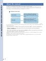
Important information before reading this manual
This manual is divided into two main parts: Safety Cautions and TS-SD guide.
In order to use the TS-SD and optional devices in an efficient manner, users should read the parts which
are pertinent to the objective in question. Moreover, after reading this manual, keep it on hand for easy
referencing as needed, and always make it available to the end user.
Configuration of this manual
• Safety Cautions
Contains the handling cautions related to the
TS-SD. Be sure to read these cautions before
using the equipment, and strictly observe them at
all times.
• TS-SD guide
Explains the TS-SD functions, as well as the
installation and operation procedures.
Be sure to read this section before starting the
operation, and strictly observe the instructions at
all times.
23001-M4-00
Use any of the following methods for referencing this manual content during TS-SD installation, operation, and
adjustment procedures.
•Keep this manual close at hand for referencing when performing installation, operation, and adjustments.
•Display the CD-ROM version of this manual onscreen for referencing when performing installation,
operation, and adjustments.
•Print out the required pages of this manual from the CD-ROM in advance, and use them for reference when
performing installation, operation, and adjustments.
Although every effort was made to ensure that this manual content is accurate and complete, please contact
YAMAHA if errors, misprints, or omissions are found.
For information related to the robot unit, support software, and other optional devices, please refer to the
operation manuals for those items.
ii
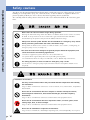
Safety aler t symbols and signal words
w
w
c
DANGER
"DANGER" indicates an imminently hazardous situation which, if not avoided, will result in death or
serious injury.
WARNING
"WARNING" indicates a potentially hazardous situation which, if not avoided, could result in death or
serious injury.
CAUTION
"CAUTION" indicates a potentially hazardous situation which, if not avoided, could result in minor or moderate
injury or damage to the equipment or software.
Indicates a prohibited action related to the handling of this product. Read the content
carefully to ensure that the prohibited action is not performed.
[Example]
Indicates a mandatory action related to the handling of this product. Read the content
carefully to ensure that the mandatory action is performed.
[Example]
Mandatory action
Cut off power
iii
Important information before reading this manual
The following safety alert symbols and signal words are used in this manual to describe safety concerns,
handling precautions, prohibited or mandatory action and key points when using this product. Make sure
you fully understand the meaning of each symbol and signal word and comply with the instructions.
CE marking
Important information before reading this manual
1. Safety standard
■ ■ Cautions regarding compliance with EC Directives
The YAMAHA robot (robot and driver) is not, in itself, a robot system. The YAMAHA robot is just one component that is
incorporated into the customer's system (built-in equipment), and YAMAHA robots are in compliance with the EC
Directives as they apply to built-in equipment. Therefore, this does not guarantee EC Directive compliance in cases
where the robot is used independently. Customers who incorporate a YAMAHA robot into a system which will be
shipped to, or used in, the EU, should therefore verify that the overall system is compliant with EC Directives.
● Differences between a YAMAHA robot (robot and driver), and a robot system:
A YAMAHA robot (robot and driver) is just one component in a robot system, and is not, in itself, a robot system.
This is because a YAMAHA robot does not include the "end effectors" or "any equipment, devices, or sensors required for
the robot to perform its tasks", as defined in the EN10218-1:2006 Standard, Item –3.20.
■ ■ Applicable EC Directives and their related standards
The following table lists the Directives (and related standards) which apply to the robot's CE Marking compliance.
EC Directive
Related Standards
Machinery
Directive
2006/42/EC
EN ISO12100-1: Safety of machinery - Basic concepts Part1
EN ISO12100-2: Safety of machinery - Basic concepts Part2
EN ISO14121-1: Safety of machinery - Risk assessment
EMC Directive
2004/108/EC
EN 55011
: EMC Emission of ISM Equipment
EN 61000-6-2 : EMC Immunity for Industrial Environments
Referred standards: EN ISO10218-1: Safety requirements - Part1:Robot
■ ■ Cautions regarding the official language of EU countries
For YAMAHA robots that will be installed in EU countries, the language used for the user's manuals, CE declarations,
and operation screen characters is English only, except for warning labels.
Warning labels only have pictograms or else include warning messages in English. In the latter case, Japanese language
messages might be added.
2. Safety measures
■ ■ Usage Conditions
The usage conditions which apply to the YAMAHA robot series are described below.
• EMC (Electromagnetic Compatibility)
YAMAHA robots are designed for industrial environments. (Applicable standard relating to the EMC Directive: Refer to
the EN61000-6-2 Standard, Item 1 "Scope".)
EMC Directive compliance requires that the customer have the final product (over equipment system) evaluated, with
any necessary measures being implemented.
• Explosion-proof
The robot and driver do not have explosion-proof specifications, and the robot should therefore not be used in
environments exposed to flammable gases which could explode or ignite, or to gasoline and solvents, etc.
iv
3. EMC countermeasure example
c
CAUTION
The examples shown here are the countermeasures tested under our installation conditions. When our product is
installed in the customer's system, the test results may differ due to the difference in the installation conditions.
● Configuration
EMC countermeasure example
TS-SD
*
Power supply
(200V)
Ground
AC/DC
converter
24V
MP24V ROB I/O
CP24V
0V
IO
Single-axis robot
PLC
COM1
Power connector
External safety circuit
* AC/DC converter JWS100-24: made by TDK Lambda
23002-M4-00
v
Important information before reading this manual
Regarding EMC directives, the customer's final product (entire system) including the YAMAHA robot must
provide the necessary countermeasures. We at YAMAHA determine a model for single units of YAMAHA robots
(driver, robot, and peripheral device) and verify that it complies with the relevant standards of EMC directives.
In order to ensure the customer's final product (entire system) complies with EMC directives, the customer
should take appropriate EMC countermeasures. Typical EMC countermeasures for a single unit of YAMAHA
robot are shown for your reference.
Safety cautions
Important information before reading this manual
The driver was designed and manufactured with ample consideration given to safety. However, incorrect
handling or use may lead to injury, fire, electrical shocks, or other accidents or equipment failures. To
prevent possible problems, be sure to observe the following safety cautions at all times.
Also carefully read the safety cautions listed in the robot user's manual and follow all instructions given
there.
Never enter the robot movement range during operation.
Entering the movement range while the robot is in motion could result in serious accidents
or death. A safety enclosure or area sensor with a gate interlock function should be
installed to keep all persons safely out of the robot's movement range.
Always turn the main power breaker OFF and establish an "emergency stop" status
before performing tasks within the robot's movement range.
Failing to do so could result in serious accidents or death. (See section 7, "Configuring an
emergency stop circuit", in Chapter 2.)
The driver and robot were designed as general-purpose industrial equipment, and
cannot be used for the following applications.
· In medical equipment systems which are critical to human life.
· In systems which significantly affect society and the general public.
· In environments which are subject to vibration, such as aboard ships and vehicles.
For safety purposes, be sure to install an "emergency stop" circuit.
Use the driver's "emergency stop" input terminal to install a main power shutoff circuit
(required).
• Installation environment
Use only in environments where the prescribed ambient temperature and humidity
are maintained.
Usage in other environments could cause electrical shocks, fires, malfunctions, and product
deterioration.
Do not use in environments which are subject to vibration and impact shocks,
electromagnetic interference, electrostatic discharges, and radio frequency
interference.
Usage in these environments could cause malfunctions and equipment failure.
Do not use in environments which are exposed to water, corrosive gases, metal
cutting chips, dust, or direct sunlight.
Usage in these environments could cause malfunctions and equipment failure.
Do not use in flammable or explosive environments.
Usage in these environments could hamper operating tasks, and could possibly cause injuries.
vi
• Installation environment
Secure the equipment firmly to a non-flammable vertical wall of metal material.
The driver becomes hot during operation, and must be secured to a metal wall in order to
prevent the risk of fires.
Install in a well ventilated site with ample space around the equipment.
Failing to do so could cause malfunctions, equipment failure, and fires.
• Wiring and connections
Always shut off the power to the driver before performing wiring work and
connecting cables.
Failing to do so could result in electrical shocks and equipment failure.
When connecting cables, use care to avoid subjecting the connectors to impact
shocks or excessive loads.
Failing to do so could result in connector pin deformation, and internal PCB damage.
Handle cables with care to avoid damaging them.
Do not attempt to modify the cables, and avoid pulling them or placing heavy objects on
them. These actions could damage the cable, possibly resulting in malfunctions and
electrical shocks.
Be sure that cable connectors and terminals are fully inserted and securely fastened.
Tighten the fastening screws securely. Failing to do so could cause a poor connection,
possibly resulting in malfunctions.
Securely ground the power terminal block's ground terminal.
Failing to do so could result in malfunctions or breakdowns.
• Operation and handling
The driver should be operated only by personnel who have received safety and
operation training.
Operation by an untrained person is extremely hazardous.
Set the payload, acceleration, and deceleration to appropriate values.
Payload, acceleration, and deceleration settings which differ greatly from the actual values
will result in operation time loss, shorten the robot life, and cause vibration. Be sure to set
them to appropriate values.
Do not enter the robot's movement range while power is supplied to the driver.
Doing so could result in a serious accident, injury, or death.
Do not touch the driver or robot during operation.
The driver or robot main body becomes hot during operation, and touching them could
result in burn injuries.
vii
Important information before reading this manual
Provide ample space to ensure that tasks (teaching, inspections, etc.) can be
performed safely.
Failing to provide adequate space makes tasks difficult to perform, and can cause injuries.
• Operation and handling
Important information before reading this manual
Do not remove the driver cover and do not attempt to disassemble or modify the
driver.
Doing so could result in fires or equipment failure.
Do not touch or operate the driver with wet hands.
Doing so could result in electrical shocks or equipment failure.
Immediately turn off the power if abnormal odors, sounds, or smoke are noticed
during operation.
Failing to do so could result in electrical shocks, fires, or equipment failure. Stop operation
immediately, and contact your YAMAHA representative.
• Maintenance and inspection
Perform maintenance and inspection tasks only when instructions for doing so are
provided by YAMAHA.
Maintenance and inspection of the driver or robot performed by a person who lacks the
proper knowledge or training is extremely hazardous.
Shut off the power to the driver before performing inspections and maintenance
tasks.
Shut off the power before beginning the tasks.
Failing to do so could result in electrical shocks or burn injuries.
Use the driver and robot only in the prescribed combinations.
Unsuitable combinations could result in fires and equipment failure.
Save the driver's internal data to an external memory device.
The driver's internal data could be unexpectedly lost, and should therefore be backed up to
an external device.
When disposing of this product, it must be handled as industrial waste.
Either dispose of the product in accordance with the local regulations, or engage a
commercial disposal service to handle the disposal.
viii
Warranty
■ ■ This warranty does not cover any failure caused by:
1.Installation, wiring, connection to other control devices, operating methods, inspection or maintenance that does not
comply with industry standards or instructions specified in the YAMAHA manual;
2.Usage that exceeded the specifications or standard performance shown in the YAMAHA manual;
3.Product usage other than intended by YAMAHA;
4.Storage, operating conditions and utilities that are outside the range specified in the manual;
5.Damage due to improper shipping or shipping methods;
6.Accident or collision damage;
7.Installation of other than genuine YAMAHA parts and/or accessories;
8.Modification to original parts or modifications not conforming to standard specifications designated by YAMAHA,
including customizing performed by YAMAHA in compliance with distributor or customer requests;
9.Pollution, salt damage, condensation;
10.Fires or natural disasters such as earthquakes, tsunamis, lightning strikes, wind and flood damage, etc;
11.Breakdown due to causes other than the above that are not the fault or responsibility of YAMAHA;
■ ■ The following cases are not covered under the warranty:
1.Products whose serial number or production date (month & year) cannot be verified.
2.Changes in software or internal data such as programs or points that were created or changed by the customer.
3.Products whose trouble cannot be reproduced or identified by YAMAHA.
4.Products utilized, for example, in radiological equipment, biological test equipment applications or for other purposes
whose warranty repairs are judged as hazardous by YAMAHA.
THE WARRANTY STATED HEREIN PROVIDED BY YAMAHA ONLY COVERS DEFECTS IN PRODUCTS
AND PARTS SOLD BY YAMAHA TO DISTRIBUTORS UNDER THIS AGREEMENT. ANY AND ALL OTHER
WARRANTIES OR LIABILITIES, EXPRESS OR IMPLIED, INCLUDING BUT NOT LIMITED TO ANY IMPLIED
WARRANTIES OF MERCHANTABILITY OR FITNESS FOR A PARTICULAR PURPOSE ARE HEREBY EXPRESSLY
DISCLAIMED BY YAMAHA. MOREOVER, YAMAHA SHALL NOT BE HELD RESPONSIBLE FOR CONSEQUENT
OR INDIRECT DAMAGES IN ANY MANNER RELATING TO THE PRODUCT.
Ver.1.00_201205
ix
Important information before reading this manual
For information on the warranty period and terms, please contact our distributor where you purchased the
product.
Chapter 1 Overview
Contents
1. Unpacking check
1-1
2. Part names and functions
1-1
3. System configuration
1-2
4. Installation and operation sequence
1-3
1. Unpacking check
1
The following accessories are shipped together with this product.
1 unit
Power connector
1 piece
I/O cable
1 piece
Overview
TS-SD
2. Par t names and functions
This section explains the part names and functions of the TS-SD.
Part names and functions
• Communication connector 2
(COM2)
Connector for the daisy-chain
connection cable.
• Robot I/O connector (ROB I/O)
Connector for robot peripheral I/O
signals such as position and
brake signals, etc. and motor
power lines.
• I/O connector (I/O)
Connector for connection to the
host unit, such as PLC.
• Power supply connector
Connector for main power and
control power input.
• Status indicator lamps
(PWR, ERR)
The TS-SD status is indicated by
LED lamps.
(See section 4, “LED status
indicators", in Chapter 5.)
• Serial No.
• Communication connector 1 (COM1)
Connector for connection to a
personal computer
• Rating nameplate
(on side face of unit body)
23101-M4-00
1-1
1
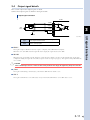
3. System configuration
A robot or PLC is connected to the TS-SD to configure a desired system.
System configuration diagram
Overview
• Support software
Support software (TS-Manager) and dedicated
connection cable are optional items.
TS-Manager
Personal computer
• Single-axis robot
TRANSERVO series robot.
• I/O control
PLC, etc.
External control
(PLC, etc.)
23102-M4-00
1-2
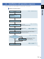
4. Installation and operation sequence
1
The basic sequence from TS-SD installation to actual operation is shown below.
Installation and operation sequence
Overview
Chapter 2 ”Installation and wiring”
Installation
· Cable and connector wiring
and connection
· Ground connection
· Building the "emergency stop" circuit
Power ON
· E-Gear setting
· Command pulse parameter setting
Parameter setting
· Machine reference
check
Origin return
Trial operation, adjustment, teaching
Alarm occurs?
No
Operation
Chapter 4 "Data setting"
Chapter 3 "I/O signal functions"
Chapter 5 "Operation"
· Verifying that operation can be executed from the host unit.
· Operation pattern and peripheral device matching
· Command pulse adjustment
Yes
Alarm cause correction
Chapter 6 "Troubleshooting"
· Check by LED status indications
· Check the alarm No.
· Correct the alarm cause
Chapter 3 "I/O signal functions"
Chapter 5 "Operation"
23103-M4-00
1-3
Chapter 2 Installation and wiring
Contents
1. Installation method
2-1
2. Installation conditions
2-2
3. Power supply connection
2-3
4. Connecting the robot
2-5
5. Connecting the I/O connector
2-6
5.1
Connecting the I/O cable (open collector specifications)
2-7
5.2
Connecting the I/O cable (line driver specifications)
2-9
6. Connecting the communication unit
2-11
7. Configuring an emergency stop circuit
2-12
1. Installation method
Use the mounting screw holes to install the TS-SD on a vertical wall in the manner shown below.
Installation
2
■ ■ Installation screws
Use the following screw type for installation.
Mounting Area Thickness
Hole Dia.
Recommended Screw
Recommended Tightening Torque
5mm
φ4.5
M4
0.5 N·m
2-1
Installation and wiring
23201-M4-00
2. Installation conditions
This section explains the installation conditions necessary to operate the TS-SD in safe and correct manner.
■ ■ Installation location
2
Install the TS-SD inside the control panel.
■ ■ Installation direction
Install the TS-SD on a vertical wall.
■ ■ Surrounding space
Installation and wiring
Install the TS-SD in a well ventilated location, with space on all sides of the TS-SD. (See the figure below.)
Surrounding space
20mm
or more
10mm
or more
10mm
or more
20mm
or more
23202-M4-00
■ ■ Ambient operating temperature and humidity
The TS-SD’s ambient operating temperature and humidity must be maintained within the following ranges.
• Ambient temperature :0 to 40˚C
• Ambient humidity
:35 to 85% RH (no condensation)
■ ■ Environments to be avoided
To ensure safe and correct TS-SD operation, avoid using the driver in the following environments.
• Environments which contain corrosive gases such as sulfuric acid or hydrochloric acid, or where flammable gases and
liquids are present in the atmosphere.
• Environments with excessive dust.
• Environments which contain metal cutting chips, oil, and water, etc., from other machinery.
• Environments subject to excessive vibration.
• Environments where electromagnetic noise or electrostatic noise is generated.
• Environments exposed to direct sunlight.
c
2-2
CAUTION
• Do not install the TS-SD upside down or at an angle. Doing so could reduce the cooling capacity and cause performance deterioration or malfunctions.
• Provide the prescribed spacing between the TS-SD and the inner face of the control panel, and between the TS-SD and other device. Otherwise, malfunctions may result.
• Avoid using the driver in environments other than those specified. Usage in inappropriate environments could cause product deterioration and malfunctions.
3. Power supply connection
Use the power connector supplied with the TS-SD to connect the power supply.
■ ■ Power supply connector terminal names and functions
2
Power supply connector
Signal name
No connection terminal
ES-
Emergency stop ready signal (open: emergency stop)
MP24V
Main power supply 24V
CP24V
Control power supply 24V
0V
Power supply 0V
Ground terminal
23204-M4-00
c
CAUTION
• Always ground the ground terminal to prevent equipment malfunctions which may be caused by noise.
• Do not connect any signal to the NC terminal. Doing so may cause the driver to break.
• Use as short a cable as possible to ground the ground terminal.
■ ■ Power supply connection examples
Power supply connection examples
TS-SD
NC
NC
AC/DC switching power supply, etc.
*1
ESMP24V
+24V
0V
CP24V
0V
FG
23203-M4-00
*1 : Main power shutoff contact. For details, see section 7, "Configuring an emergency stop circuit".
c
CAUTION
Be sure that the power supply voltage and the terminal connections are correct. Incorrect voltage and
connections could cause an equipment failure.
■ ■ Power requirements
c
Voltage
24VDC ± 10%
Current
Control power supply: 0.5A per unit
Main power supply : 2.5 to 4.0A per unit
Recommended wire size
0.5 to 0.75 sq (AWG 20 to 18)
CAUTION
• If the current supplied to the TS-SD is too low, alarm stop or abnormal operation may occur. Carefully select a 24V power supply that provides an adequate current capacity.
• Since the TS-SD uses a capacitor input type power supply circuit, a large inrush current flows when the power is turned on. Do not use fast-blow circuit breakers and fuses.
For the same reason, avoid turning the power off and on again repeatedly in intervals of less than 10 seconds. This could harm the main circuit elements in the TS-SD.
2-3
Installation and wiring
NC
NC
ESMP24V
CP24V
0V
Description
NC
■ ■ Signal Details
• Emergency stop READY signal (ES-)
This signal is used by the external safety circuit (e.g., safety enclosure, manual switch, etc.) in order to perform robot
emergency stops.
Signal Name
ES-
2
Description
Emergency stop input (emergency stop READY signal)
Type
Input
Explanation
An emergency stop status is established when this signal input is switched OFF, and a "servo OFF" status also occurs at
that time.
Installation and wiring
w
DANGER
When the power supply (+24V) is directly connected to the signal "ES-", the external emergency stop
cannot be used and this is very dangerous. Be sure to configure an appropriate emergency stop
circuit.
■ ■ Power supply connector wiring procedure
c
CAUTION
• Unplug the power connector from the TS-SD before wiring.
• Only one wire can be inserted into one wire hole of the power connector.
• When inserting the wire into the terminal, use care to prevent the core wire from making contact with other conductive parts.
• If the inserted portion of the wire is frayed, etc., cut off that portion and restrip the wire, then connect the wire securely.
The usable wire size is 0.5 to 0.75sq (AWG20 to 18). Strip the sheath from the wire and insert it as shown below.
Insert the core wire into the power supply connector's hole as shown below, then verify that the wire is locked (cannot
be pulled out).
Wiring method
Insert the wire while pushing the orange part.
23205-M4-00
2-4
4. Connecting the robot
Connect the robot cables to the robot I/O connector on the front panel of the TS-SD.
c
CAUTION
• Be sure to use the cable dedicated to the TS when connecting the robot.
• Shut the power off before connecting the cables.
• Insert the cable plug into the connector until a clicking sound is heard (fully inserted).
• Connect only the robot which is to be used.
• Always grasp the connector body when plugging in and unplugging the cables.
2
Installation and wiring
■ ■ Connection method
Connecting the robot
TS-SD
Robot I/O connector
TRANSERVO series
23209-M4-00
■ ■ Robot I/O connector signal table
Pin No.
Signal Name
Description
1A
PS+
Resolver SIN input (+)
1B
PS-
Resolver SIN input (-)
2A
PC+
Resolver COS input (+)
2B
PC-
Resolver COS input (-)
3A
R+
Resolver excitation output (+)
3B
R-
Resolver excitation output (-)
4A
FG
4B
FG
5A
BK+
Brake signal (+)
5B
BK-
Brake signal (-)
6A
A+
Motor "phase A" output (+)
6B
A-
Motor "phase A" output (-)
7A
ACOM
Motor "phase A" common
7B
BCOM
Motor "phase B" common
8A
B+
Motor "phase B" output (+)
8B
B-
Motor "phase B" output (-)
Frame ground
2-5
2
5. Connecting the I/O connector
This I/O connector is intended to connect the host unit, such as PLC.
The return-to-origin or pulse train command operation can be performed from the host unit through the I/O
interface.
There are two kinds of pulse train command input methods available, open collector method and line driver
method. The TS-SD can be made applicable to either the open collector method or line driver method by
changing the signal wiring connections and parameter settings. So, make appropriate connections and
parameter settings suitable for the specifications of the host unit.
For details about input and output signals, see Chapter 3, I/O signal functions.
Installation and wiring
I/O connector connection
I/O connector
External control
(PLC, etc.)
21211-M4-00
c
2-6
CAUTION
Be sure to perform the wiring with great care so that incorrect terminal numbers are not connected or any line
between the terminals is not short-circuited. Incorrect wiring may cause the driver to break.
Before starting the wiring work, carefully check the terminal assignments and connect the I/O connector so that
any line between the terminals is not short-circuited.
5.1
Connecting the I/O cable (open collector specifications)
The following shows an example of I/O signal connections to the host unit when the pulse train command
input method is the open collector method.
Connection example
2m or less
Shielded cable
5V to 24V
Pulse
generator
TS-SD
2
OPC
PULS1
Connection prohibited.
PULS2
Installation and wiring
DIR1
Connection prohibited.
DIR2
+COM
ORG-S
24V
INPOS
SRV-S
/ALM
ORG
RESET
SERVO
NC
-COM
Ground
23207-M4-00
w
WARNING
• Be sure to ground the shield of the I/O cable. Failure to do so may cause a malfunction by noise.
• Be sure to use an appropriate shielded cable with a length of 2m or less for the I/O cable.
• Do not connect any resistor to the pulse train command input interface. The pulse train command input interface uses a photo-coupler. So, if any resistor is connected to the signal line, the current
decreases, causing a malfunction.
• A pull-up resistor may be incorporated into the open collector output of the pulse generator. In this case, remove the pull-up resistor or use a port without pull-up resistor. If the pull-up resistor is used, the current decreases, causing a malfunction.
• When using the open collector method, do not connect any signal to the PULS1 and DIR1 terminals. Doing so may cause the driver to malfunction or break.
• Be sure to connect one TS-SD to one pulse generator.
If multiple drivers are connected in parallel, this may cause a malfunction.
• Be sure to perform the wiring with great care so that incorrect terminal numbers are not connected or the line between the terminals is not short-circuited. Incorrect wiring may cause the
driver to break or malfunction.
2-7
Color
Signal
Name
Terminal
No.
Ground
Drain line
FG
16
Servo status
Green
(white dot)
SRV-S
Blue
(red dot)
IN-POS
12
Servo ON
Purple
SERVO
10
Prohibited to use this
signal.
Yellow
NC
8
Red
DIR2
6
Command pulse input
Brown
PULS2
Open collector power
supply input
Orange
OPC
Description
Positioning completion
2
Command direction
input
Installation and wiring
Terminal
No.
Signal
Name
15
-COM
13
/ALM
11
ORG-S
9
RESET
Pink
Reset
7
ORG
Black
Return-to-origin
5
DIR1
Gray
4
3
PULS1
Green
Not used
(Connection prohibited.)
2
1
+COM
Blue
I/O power supply input
(DC 24V ± 10%)
14
16
14
12
10
8
6
4
2
15
13
11
9
7
5
3
1
Color
Brown
(white dot)
Description
0V
Orange
Alarm
(white dot)
White
Return-to-origin end
status
Not used
(Connection prohibited.)
* It is prohibited to connect terminal Nos. 3 (PULS1)
and 5 (DIR1).
23212-M4-00
2-8
5.2
Connecting the I/O cable (line driver specifications)
The following shows an example of I/O signal connections to the host unit when the pulse train command
input method is the line driver method.
Connection example
Line driver
(AM26LS31 or equivalent)
TS-SD
Shielded cable
2
OPC
Connection prohibited.
PULS1
PULS2
DIR1
Installation and wiring
DIR2
24V
SG
+COM
ORG-S
INPOS
SRV-S
/ALM
ORG
RESET
SERVO
NC
-COM
Ground
23208-M4-00
w
WARNING
• Be sure to ground the shield of the I/O cable. Failure to do so may cause a malfunction by noise.
• Be sure to use an appropriate TWISTED PAIR shielded cable for the I/O cable.
• Do not connect any resistor to the pulse train command input interface. The pulse train command input interface uses a photo-coupler. So, if any resistor is connected to the signal line, the current
decreases, causing a malfunction.
• When using the line driver method, do not connect any signal to the OPC terminal.
Doing so may cause the driver to malfunction or break.
• Be sure to perform the wiring with great care so that incorrect terminal numbers are not connected or the line between the terminals is not short-circuited. Incorrect wiring may cause the
driver to break or malfunction.
2-9
Color
Signal
Name
Terminal
No.
Ground
Drain line
FG
16
Servo status
Green
(white dot)
SRV-S
14
Blue
(red dot)
IN-POS
12
Servo ON
Purple
SERVO
10
Prohibited to use this
signal.
Yellow
NC
8
Red
DIR2
Brown
Orange
Description
Positioning completion
2
Command direction
input (-)
Installation and wiring
Command pulse input
(-)
Not used
(Connection prohibited.)
Terminal
No.
Signal
Name
15
-COM
Brown
0V
(white dot)
13
/ALM
Orange
Alarm
(white dot)
11
ORG-S
White
9
RESET
Pink
Reset
7
ORG
Black
Return-to-origin
6
5
DIR1
Gray
Command direction
input (+)
PULS2
4
3
PULS1
Green
Command pulse input
(+)
OPC
2
1
+COM
Blue
I/O power supply input
(DC 24V ± 10%)
* It is prohibited to connect terminal No. 2 (OPC).
2-10
16
14
12
10
8
6
4
2
15
13
11
9
7
5
3
1
Color
Description
Return-to-origin end
status
23212-M4-00
6. Connecting the communication unit
The TS-SD can be set up or operated from a personal computer (support software TS-Manager).
• Support software TS-Manager Ver. 1.3.0 or higher is required to operate the TS-SD.
• An optional communication connection cable is required to connect the TS-SD to the personal computer.
■ ■ Connecting to the personal computer
2
Use the dedicated communication connection cable that is available as an optional item.
w
CAUTION
• Select either the USB or D-Sub connection cable for the communication cable. When performing the communication through the USB port of the personal computer, use an appropriate USB connection communication cable. If the D-Sub communication cable is connected to the USB port through a commercially
available USB conversion cable, the operation cannot be guaranteed.
• Do not modify the communication cable. This can cause communication errors and equipment failure.
• Always grasp the connector body when connecting/disconnecting the communication cable to/from the driver. Pulling on the cable can cause equipment failure or breaking of wire.
• An incorrectly inserted connector or poor contact condition can cause malfunctions or equipment failure.
Be sure that the connector is correctly and securely connected.
• When disconnecting the connector from the driver, pull the connector straight out to avoid bending the connector pins.
Communication device connection
Communication connector 1 (COM1)
Personal computer
Communication cable
23210-M4-00
2-11
Installation and wiring
c
WARNING
Do not operate the robot using the TS-Manager within the robot movable area.
7. Configuring an emergency stop circuit
The power supply connector provides functions for configuring safety circuits, including the robot. The
following shows a power connector and host unit connection example.
Emergency stop circuit example
TS-SD
2
COM1
Installation and wiring
External 24V
External "emergency stop"
RY
External 0V
NC
NC
ESMP24V
CP24V
0V
ES
Status
Internal
GND
External 0V
23206-M4-00
w
w
2-12
DANGER
In order to flexibly accommodate the various safety categories required by customers, the TS-SD is
not equipped with an internal main power shutoff circuit.
Therefore, be sure to install an external main power shutoff circuit and an "emergency stop" circuit.
DANGER
When the power supply (+24V) is directly connected to the signal "ES-", the external emergency stop
cannot be used and this is very dangerous. Be sure to configure an appropriate emergency stop
circuit.
Chapter 3 I/O signal functions
Contents
1. I/O specifications
3-1
2. Open collector specifications
3-2
2.1
I/O signal table
3-2
2.2
I/O signal list
3-2
2.3
Input signal details
3-3
2.3.1
2.3.2
Command pulse input and command direction input (OPC, PULS2, DIR2)
I/O inputs
2.4
Output signal details
3. Line driver specifications
3-3
3-5
3-6
3-7
3.1
I/O signal table
3-7
3.2
I/O signal list
3-7
3.3
Input signal details
3-8
3.3.1
3.3.2
Command pulse input and command direction input (PULS1, PULS2, DIR1, DIR2)
3-8
I/O inputs
3-10
3.4
Output signal details
3-11
1. I/O specifications
The return-to-origin or pulse train command operation can be performed from the host unit through the
I/O interface. There are two kinds of pulse train command input methods available, open collector method
and line driver method. The TS-SD can be made applicable to either the open collector method or line driver
method by changing the signal wiring connections and parameter settings. So, make appropriate connections
and parameter settings suitable for the specifications of the host unit.
3
I/O signal functions
3-1
2. Open collector specifications
2.1
I/O signal table
Terminal
No.
I/O connector
15
13
11
9
7
5
3
1
16
14
12
10
8
6
4
2
3
Signal
Name
Description
Terminal
No.
Signal
Name
Description
I/O signal functions
1
+COM
I/O power supply input
(DC 24V ± 10%)
2
OPC
Open collector power
supply input
3
PULS1
Not used
(Connection prohibited.)
4
PULS2
Command pulse input
5
DIR1
Not used
(Connection prohibited.)
6
DIR2
Command direction input
7
ORG
Return-to-origin
8
NC
Prohibited to use this signal.
9
RESET
Reset
10
SERVO
Servo ON
11
ORG-S
Return-to-origin end status
12
IN-POS
Positioning completion
13
/ALM
Alarm
14
SRV-S
Servo status
15
-COM
0V
16
FG
Ground
23311-M4
2.2
Type
Inputs
I/O signal list
Signal Name
Meaning
OPC
Open collector power supply
input
PULS2
Command pulse input
DIR2
Command direction input
ORG
Return-to-origin
Starts return-to-origin when ON and stops it when OFF.
RESET
Reset
Alarm reset
SERVO
Servo ON
ON: servo on; OFF: servo off.
ORG-S
Return-to-origin end status
ON at return-to-origin end.
IN-POS
Positioning completion
ON when the pulse accumulation in the deviation counter
becomes within ± set value of the parameter K3.
/ALM
Alarm
ON when normal. OFF when alarm occurs.
SRV-S
Servo status
ON when servo is on.
Outputs
c
3-2
Description
Input the power supply for the open collector.
DC5 to 24V ± 10%
Pulse train command input terminals. A desired command form
can be selected from three kinds of command forms using the
parameter K83 (pulse train input type).
• Phase A/Phase B input
• Pulse/Sign input
• CW/CCW input
CAUTION
When using the open collector specifications, do not connect any signal to the PULS1 and DIR1 terminals. Doing
so may cause the driver to malfunction or break.
2.3
Input signal details
This section explains the input signals in detail.
2.3.1 Command pulse input and command direction input (OPC, PULS2, DIR2)
Connect the pulse train command inputs as shown in the figure below.
Pulse train command input connection
2m or less
Shielded cable
5V to 24V
±10%
TS-SD
OPC
3
PULS1/DIR1
Connection prohibited.
PULS2/DIR2
-COM
Ground
23301-M4-00
c
w
CAUTION
Use the open collector output power supply in a range of DC5 to 24V ± 10%.
It is not necessary to insert any load resistor even when the voltage differs.
WARNING
• Be sure to ground the shield of the I/O cable. Failure to do so may cause a malfunction by noise.
• Be sure to use an appropriate shielded cable with a length of 2m or less for the I/O cable.
• Do not connect any resistor to the pulse train command input interface. The pulse train command input interface uses a photo-coupler. So, if any resistor is connected to the signal line, the current
decreases, causing a malfunction.
• A pull-up resistor may be incorporated into the open collector output of the pulse generator. In this case, remove the pull-up resistor or use a port without pull-up resistor. If the pull-up resistor is used, the current decreases, causing a malfunction.
• When using the open collector method, do not connect any signal to the PULS1 and DIR1 terminals. Doing so may cause the driver to malfunction or break.
• Be sure to connect one TS-SD to one pulse generator.
If multiple drivers are connected in parallel, this may cause a malfunction.
• Be sure to perform the wiring with great care so that incorrect terminal numbers are not connected or the line between the terminals is not short-circuited. Incorrect wiring may cause the
driver to break or malfunction.
Kind of pulse train
K83
Input signal
PULS2
(Transistor)
CW/CCW
PULS2
(Transistor)
*
(OFF)
(OFF)
(ON) (OFF) (ON) (OFF) (ON) (OFF)
(ON) (OFF) (ON) (OFF) (ON) (OFF)
(ON) (OFF) (ON) (OFF) (ON) (OFF)
2
DIR2
(Transistor)
Phase A/Phase B
(ON) (OFF) (ON) (OFF) (ON) (OFF)
CCW direction
1
DIR2
(Transistor)
Pulse/Sign
CW direction
(ON)
(OFF)
PULS2
(Transistor)
(ON) (OFF) (ON) (OFF) (ON) (OFF)
(ON) (OFF) (ON) (OFF) (ON) (OFF)
DIR2
(Transistor)
(ON) (OFF) (ON) (OFF) (ON)
(OFF) (ON) (OFF) (ON) (OFF)
3
stated in the table above shows the pulse train command fetch timing.
A robot (TRANSERVO series) that can be connected to the TS-SD moves in the plus-direction (toward the side
opposite to the motor) as the motor turns CW and in the minus-direction (toward the motor) as the motor turns
CCW.
3-3
I/O signal functions
FG
Pulse train command input timing
Kind of pulse train
Pulse train command input timing
(1)CW/CCW
(ON)
PULS signal
(ON)
(ON)
t2
t1
t0
T
(ON)
DIR signal
tS0
CW direction
(2)Pulse/Sign
PULS signal
3
(ON)
t1
t0
(ON)
(ON)
(ON)
CCW direction
(ON)
(ON)
(ON)
(ON)
t2
tS4
tS2
T
DIR signal
(ON)
tS1
tS3
t3
I/O signal functions
CW direction
t4
CCW direction
(3)Phase A/Phase B
PULS signal
(ON)
t1
t0
DIR signal
(ON)
(ON)
(ON)
t2
T
(ON)
CW direction
(ON)
(ON)
(ON)
CCW direction
* (ON) stated in the timing chart above shows that the transistor of the open collector pulse generator is ON.
Pulse train command input timing values
Kind of pulse train
(See above)
Open collector
(1), (2) above
(3) above
Rise time : t 2, t 4
0.4μs or less
0.4μs or less
Fall time : t 1, t 3
0.4μs or less
0.4μs or less
15μs or more
−−−
50 ± 10%
50 ± 10%
100kpps or less
25kpps or less
Timing values
Switching time: t S0, t S1, t S2, t S3, t S4
Pulse width Maximum pulse rate
3-4
: (t 0/T) × 100
2.3.2 I/O inputs
This section explains the I/O input signals in detail.
Connect the I/O input signals as shown in the figure below.
I/O input signal connection
TS-SD
+COM
24V
±10%
4.7kΩ
Input
3
-COM
FG
Ground
Type
DC input (plus common type)
Photo-coupler isolation format
Load
DC24V±10% 4.7mA
■ ■ ORG
This input executes a return-to-origin operation. This establishes the robot coordinates.
w
c
WARNING
Before starting the return-to-origin operation, make sure that the robot operation by the pulse train
command input from the host unit is not running. If the return-to-origin operation is started while
the robot is moving by the pulse train command input, the return-to-origin operation may not be
completed correctly.
CAUTION
• If this signal is turned OFF during the return-to-origin operation, the return-to-origin operation is cancelled and it
is not completed correctly. This signal must be kept turned ON until the return-to-origin is completed successfully. To verify whether or not the return-to-origin has been completed successfully, check the return-
to-origin end status output (ORG-S).
• Even when this signal is turned ON during the JOG operation or inching operation controlled from the TS-
Manager, the return-to-origin operation does not start. Additionally, the JOG operation or inching operation cannot be started from the TS-Manager while this signal is ON.
• The robot can be operated without use of this function, but the TS-SD cannot recognize the absolute position of the robot. If this function is not used, an external sensor must be installed or other similar measures must be taken so that the host unit monitors the robot position.
■ ■ RESET
If an alarm resulting from the internal cause occurs, remove the cause of the alarm and turn ON this signal to reset the
alarm. As the alarm is reset, the alarm output (/ALM) becomes ON.
Note that there are some alarms that cannot be reset.
If an alarm resulting from the external cause occurs, removing the cause of the alarm will turn ON the alarm output (/
ALM). In this case, it is not necessary to turn ON the RESET signal.
■ ■ SERVO
A servo ON status is established while this signal is ON.
The servo ON status affects the servo status output (SRV-S).
* A servo ON is not possible while an alarm is active.
c
CAUTION
A "servo OFF" should be performed only when operation is stopped. Do not use "servo OFF" to perform
emergency stops.
3-5
I/O signal functions
23304-M4-00
2.4
Output signal details
This section explains the output signals in detail.
Connect the output signals as shown in the figure below.
Output signal connection
TS-SD
+COM
Load
24V
±10%
3
Output
-COM
FG
Ground
I/O signal functions
23305-M4-00
Type
NPN open collector output (Minus common type)
Photo-coupler isolation format
Load
24VDC, 50mA per point
■ ■ ORG-S
This signal output is ON when return-to-origin is complete, and is OFF when incomplete.
When the servo turns OFF after this signal has been output, this signal also becomes OFF.
■ ■ IN-POS
When the pulse accumulation in the deviation counter becomes within ± set value of the parameter K3 (positioning
completion width), this signal becomes ON (except for return-to-origin in progress). This signal is always ON while the
servo is OFF.
c
CAUTION
If the command speed is low or if the set value of the parameter K3 is large, this signal may always become ON.
■ ■ /ALM
This signal is ON during a normal status, and switches OFF when an alarm occurs.
■ ■ SRV-S
This signal is ON while a "servo ON" status exists, and switches OFF when a "servo OFF" status occurs.
3-6
3. Line driver specifications
3.1
I/O signal table
Terminal
No.
I/O connector
15
13
11
9
7
5
3
1
16
14
12
10
8
6
4
2
Signal
Name
Description
Terminal
No.
Signal
Name
Description
+COM
I/O power supply input
(DC 24V ± 10%)
2
OPC
Not used
(Connection prohibited.)
3
PULS1
Command pulse input (+)
4
PULS2
Command pulse input (-)
5
DIR1
Command direction input (+)
6
DIR2
Command direction input (-)
7
ORG
Return-to-origin
8
NC
Prohibited to use this signal.
9
RESET
Reset
10
SERVO
Servo ON
11
ORG-S
Return-to-origin end status
12
IN-POS
Positioning completion
13
/ALM
Alarm
14
SRV-S
Servo status
15
-COM
0V
16
FG
Ground
23311-M4
3.2
Type
Inputs
I/O signal list
Signal Name
Meaning
PULS1
Command pulse input (+)
PULS2
Command pulse input (-)
DIR1
Command direction input (+)
DIR2
Command direction input (-)
Pulse train command input terminals. A desired command form
can be selected from three kinds of command forms using the
parameter K83 (pulse train input type).
• Phase A/Phase B input
• Pulse/Sign input
• CW/CCW input
ORG
Return-to-origin
Starts return-to-origin when ON and stops it when OFF.
RESET
Reset
Alarm reset
SERVO
Servo ON
ON: servo on; OFF: servo off.
ORG-S
Return-to-origin end status
ON at return-to-origin end.
IN-POS
Positioning completion
ON when the pulse accumulation in the deviation counter
becomes within ± set value of the parameter K3.
/ALM
Alarm
ON when normal. OFF when alarm occurs.
SRV-S
Servo status
ON when servo is on.
Outputs
c
Description
CAUTION
When using the line driver specifications, do not connect any signal to the OPC terminal. Doing so may cause the
driver to malfunction or break.
3-7
3
I/O signal functions
1
3.3
Input signal details
This section explains the input signals in detail.
3.3.1 Command pulse input and command direction input (PULS1, PULS2, DIR1, DIR2)
Connect the pulse train command inputs as shown in the figure below.
Pulse train command input connection
TS-SD
Shielded cable
3
OPC
Connection prohibited.
Line driver
(AM26LS31 or equivalent)
PULS1/DIR1
200Ω
PULS2/DIR2
I/O signal functions
-COM
SG
FG
Ground
23306-M4-00
w
WARNING
• Be sure to ground the shield of the I/O cable. Failure to do so may cause a malfunction by noise.
• Be sure to use an appropriate twist-pair shielded cable for the I/O cable.
• Do not connect any resistor to the pulse train command input interface. The pulse train command input interface uses a photo-coupler. So, if any resistor is connected to the signal line, the current
decreases, causing a malfunction.
• When using the line driver method, do not connect any signal to the OPC terminal.
Doing so may cause the driver to malfunction or break.
• Be sure to perform the wiring with great care so that incorrect terminal numbers are not connected or the line between the terminals is not short-circuited. Incorrect wiring may cause the
driver to break.
Kind of pulse train
K83
Input signal
CW direction
CCW direction
PULS1
PULS2
CW/CCW
5
DIR1
DIR2
PULS1
PULS2
Pulse/Sign
6
DIR1
DIR2
H
L
PULS1
PULS2
Phase A/Phase B
7
DIR1
DIR2
*
stated in the table above shows the pulse train command fetch timing.
A robot (TRANSERVO series) that can be connected to the TS-SD moves in the plus-direction (toward the side
opposite to the motor) as the motor turns CW and in the minus-direction (toward the motor) as the motor turns
CCW.
3-8
Pulse train command input timing
Kind of pulse train
(1)CW/CCW
Pulse train command input timing
"1"
PULS signal
t1
t0
"0"
t2
T
"1"
DIR signal
(2)Pulse/Sign
"0"
tS0
CW direction
CCW direction
"1"
PULS signal
t1
t0
"0"
t2
tS4
tS2
T
"1"
DIR signal
tS3
t3
CW direction
t4
"0"
CCW direction
"1"
PULS signal
t1
"0"
t2
t0
T
"1"
DIR signal
"0"
CW direction
CCW direction
* When at logic "1", the current direction of the pulse train command input is PULS1 → PULS2, DIR1 → DIR2.
Pulse train command input timing values
Kind of pulse train
(See above)
Line driver
(1), (2) above
(3) above
Rise time : t 1, t 3
0.4μs or less
0.4μs or less
Fall time : t 2, t 4
0.4μs or less
0.4μs or less
4μs or more
−−−
50 ± 10%
50 ± 10%
500kpps or less
125kpps or less
Timing values
Switching time: t S0, t S1, t S2, t S3, t S4
Pulse width Maximum pulse rate
: (t 0/T) × 100
3-9
I/O signal functions
tS1
(3)Phase A/Phase B
3
3.3.2 I/O inputs
This section explains the I/O input signals in detail.
Connect the I/O input signals as shown in the figure below.
I/O input signal connection
TS-SD
+COM
24V
±10%
4.7kΩ
Input
3
-COM
FG
Ground
I/O signal functions
23309-M4-00
Type
DC input (plus common type)
Photo-coupler isolation format
Load
DC24V±10% 4.7mA
■ ■ ORG
This input executes a return-to-origin operation. This establishes the robot coordinates.
w
c
WARNING
Before starting the return-to-origin operation, make sure that the robot operation by the pulse train
command input from the host unit is not running. If the return-to-origin operation is started while
the robot is moving by the pulse train command input, the return-to-origin operation may not be
completed correctly.
CAUTION
• If this signal is turned OFF during the return-to-origin operation, the return-to-origin operation is cancelled and it
is not completed correctly. This signal must be kept turned ON until the return-to-origin is completed successfully. To verify whether or not the return-to-origin has been completed successfully, check the return-
to-origin end status output (ORG-S).
• Even when this signal is turned ON during the JOG operation or inching operation controlled from the TS-
Manager, the return-to-origin operation does not start. Additionally, the JOG operation or inching operation cannot be started from the TS-Manager while this signal is ON.
• The robot can be operated without use of this function, but the TS-SD cannot recognize the absolute position of the robot. If this function is not used, an external sensor must be installed or other similar measures must be taken so that the host unit monitors the robot position.
■ ■ RESET
If an alarm resulting from the internal cause occurs, remove the cause of the alarm and turn ON this signal to reset the
alarm. As the alarm is reset, the alarm output (/ALM) becomes ON.
Note that there are some alarms that cannot be reset.
If an alarm resulting from the external cause occurs, removing the cause of the alarm will turn ON the alarm output (/
ALM). In this case, it is not necessary to turn ON the RESET signal.
■ ■ SERVO
A servo ON status is established while this signal is ON.
The servo ON status affects the servo status output (SRV-S).
* A servo ON is not possible while an alarm is active.
c
3-10
CAUTION
A "servo OFF" should be performed only when operation is stopped. Do not use "servo OFF" to perform
emergency stops.
3.4
Output signal details
This section explains the output signals in detail.
Connect the output signals as shown in the figure below.
Output signal connection
TS-SD
+COM
Load
24V
±10%
Output
3
-COM
FG
Ground
Type
NPN open collector output (Minus common type)
Photo-coupler isolation format
Load
24VDC, 50mA per point
■ ■ ORG-S
This signal output is ON when return-to-origin is complete, and is OFF when incomplete.
When the servo turns OFF after this signal has been output, this signal also becomes OFF.
■ ■ IN-POS
When the pulse accumulation in the deviation counter becomes within ± set value of the parameter K3 (positioning
completion width), this signal becomes ON (except for return-to-origin in progress). This signal is always ON while the
servo is OFF.
c
CAUTION
If the command speed is low or if the set value of the parameter K3 is large, this signal may always become ON.
■ ■ /ALM
This signal is ON during a normal status, and switches OFF when an alarm occurs.
■ ■ SRV-S
This signal is ON while a "servo ON" status exists, and switches OFF when a "servo OFF" status occurs.
3-11
I/O signal functions
23310-M4-00
Chapter 4 Data setting
Contents
1. Data overview
4-1
2. Parameter data
4-2
2.1
Parameter list
2.1.1
2.1.2
2.1.3
2.1.4
RUN parameters
I/O parameters
Option parameters
Servo parameters
4-2
4-2
4-3
4-3
2.2
Parameter details
4-3
2.2.1
2.2.2
2.2.3
2.2.4
RUN parameters
I/O parameters
Option parameters
Servo parameters
4-3
4-4
4-5
4-6
3.
3.1
3.2
Reference graphs and tables of speed and acceleration settings using payload and stroke 4-2
4-7
Slider type
4-7
SS04-12S
SS04-06S
SS04-02S
SS04-12SB
SS04-06SB
SS04-02SB
SS05-20S
SS05-12S
SS05-06S
SS05-12SB
SS05-06SB
SS05H-20S
SS05H-12S
SS05H-06S
SS05H-12SB
SS05H-06SB
4-7
4-7
4-7
4-8
4-8
4-8
4-9
4-9
4-10
4-10
4-11
4-11
4-12
4-12
4-13
4-13
Rod type (Standard)
SR03-12S
SR03-06S
SR03-12SB
SR03-06SB
SR04-12S
SR04-06S
SR04-02S
SR04-12SB
SR04-06SB
SR04-02SB
SR05-12S
SR05-06S
4-14
4-14
4-14
4-14
4-15
4-15
4-16
4-17
4-17
4-18
4-18
4-19
4-20
SR05-02S
SR05-12SB
SR05-06SB
SR05-02SB
3.3
Rod type (With support guide)
SRD03-12S
SRD03-06S
SRD03-12SB
SRD03-06SB
SRD04-12S
SRD04-06S
SRD04-02S
SRD04-12SB
SRD04-06SB
SRD04-02SB
SRD05-12S
SRD05-06S
SRD05-02S
SRD05-12SB
SRD05-06SB
SRD05-02SB
4-21
4-21
4-22
4-22
4-23
4-23
4-23
4-24
4-24
4-25
4-26
4-27
4-28
4-29
4-30
4-31
4-32
4-33
4-34
4-34
4-35
1. Data over view
It is necessary to specify the parameter data settings in order to operate a robot from the TS-SD.
The parameter data can be set using the TS-Manager (version 1.3.0 or higher).
The parameter data is classified into the following categories: "RUN parameters", "I/O parameters", "Option
parameters", and "Servo parameters".
Data configuration
Parameter
Specifies parameter settings related
to positioning and return-to-origin
operations.
K21 to K39
I/O parameter
Specifies the parameter settings related
to the input and output functions.
K80 to K99
Option parameter
Specifies the parameter settings related
to the pulse train command input.
K40 to K79, K100 to ...
Servo parameter
Specifies the parameter settings specific
to the connected robot. These parameters
are specified during initial processing.
4
23401-M4-00
4-1
Data setting
K1 to K20
RUN parameter
2. Parameter data
The 4 types of parameter data are shown below.
Type
RUN parameter
I/O parameter
These parameters are intended for the I/O functions.
Option parameter
These parameters are related to the pulse train settings.
They include the "pulse train input type" and "E-Gear" settings.
Servo parameter
These parameters are robot-specific parameters.
They include the "gain", "rating", and "max. current" settings.
2.1
4
Description
These parameters are required for robot operation.
They include the "positioning" and "return-to-origin" settings.
Parameter list
When new data is created or transmitted, all parameters are set to their standard values (default values) in
accordance with the specifications of the selected robot and the payload. The following list shows the
parameter setting ranges and default settings.
n
Data setting
NOTE
For details regarding parameters see section 2.2, "Parameter details".
2.1.1 RUN parameters
• Positioning
No.
Name
Setting / Setting Range
Units
Default
Restart
1
(-) soft limit
(JOG operation only)
-9999.99 to 9999.99
mm
0.00
-
2
(+) soft limit
(JOG operation only)
-9999.99 to 9999.99
mm
Depends on robot type
-
3
In-position
0.01 to 1.00
mm
0.01
-
10
JOG speed
1 to 100
%
100
-
11
Inching width
0.01 to 1.00
mm
1.00
-
Units
Default
Restart
mm/s
20.00
-
-
Depends on robot type
-
Units
Default
Restart
-
0
-
ms
2
-
• Return-to-origin
No.
Name
Setting / Setting Range
13
Origin speed
0.01 to 100.00
14
Origin dir.
0: CCW direction; 1: CW direction
2.1.2 I/O parameters
• Function selection
No.
4-2
Name
Setting / Setting Range
31
SERVO sequence
0: Edge
33
Input filter
1 to 10
1: Level
2.1.3 Option parameters
• Pulse train
No.
Name
Setting / Setting Range
Pulse train invalid *
Open collector CW/CCW
Open collector Pulse/Sign
Open collector Phase A/Phase B
Line driver CW/CCW
Line driver Pulse/Sign
Line driver Phase A/Phase B
Units
Default
Restart
-
0
Required
83
Pulse train input type
0:
1:
2:
3:
5:
6:
7:
84
E-Gear 1
1 to 32767
-
20480
Required
85
E-Gear 2
1 to 32767
-
Depends on robot type
Required
* These parameters are set when the JOG operation, inching operation or return-to-origin is started from the support software
(TS-Manager).
2.1.4 Ser vo parameters
4
• Adjustment (for user adjustments)
No.
Setting / Setting Range
0 to value depending on robot type
Units
Default
Restart
kg
Depends on robot type
m/s 2
Depends on robot type
*1
77
Max. payload accel.1
(Depends on robot type)
0.01 to value depending on robot type
* The values shown above are changed according to the specified calculation formula when registering the parameter K76.
2.2
Parameter details
The parameters described below can be adjusted to conform to the actual application and usage conditions.
w
WARNING
Before changing the parameters, make sure that the servo is turned off and the pulse train command
input from the host unit is stopped completely. Failure to do so may cause an unexpected operation.
2.2.1 RUN parameters
• Positioning related parameters
K1
K2
Soft limit (-)
(JOG operation only)
Soft limit (+)
(JOG operation only)
Setting Range
Default
Units
Restar
-9999.99 to 9999.99
Depends on robot type
mm
-
Function
Specifies the robot movement range when the JOG operation is started from the support software (TS-Manager). K1
specifies the minus-side limit, and K2 specifies the plus-side limit.
Although the robot's effective stroke was factory-set as the soft limit at shipment, it should be changed if necessary to
avoid collisions with obstacles, etc. only when the return-to-origin has been completed.
TIP
For the plus and minus directions, the robot motor side becomes the minus direction and the side opposite to the
motor becomes the plus direction.
K3
Setting Range
Default
Units
Restart
0.01 to 1.00
Depends on robot type
mm
-
In-position
Function
Specifies the range in which end-of-positioning is recognized.
When the robot is located in a range specified by this parameter in response to the pulse train command input, the
IN-POS I/O signal becomes ON.
4-3
Data setting
76
Name
Payload 1
(JOG operation only)
TIP
The IN-POS signal may continue ON if this value is large or depending on the movement speed.
K10
Setting Range
Default
Units
Restart
1 to 100
100
%
-
JOG speed
Function
Specifies the JOG movement speed when the JOG movement is started from the support software (TS-Manager). A setting
of 100% is 100mm/s.
K11
Setting Range
Default
Units
Restart
0.01 to 1.00
0.01
mm
-
Inching width
Function
4
Specifies the inching amount when the inching movement is started from the support software (TS-Manager).
• Return-to-origin related parameters
K13
Data setting
Setting Range
Default
Units
Restart
0.01 to 100.00
Depends on robot type
mm/s
-
Return-to-origin speed
Function
Specifies the return-to-origin movement speed.
c
CAUTION
If a large value is set for the parameter "Origin speed" (K13), the alarm 89, "POSITION ERROR", may occur during
return-to-origin. If this happens, adjust the parameter to decrease "Origin speed" (K13).
K14
Setting Range
Default
Units
Restart
0 to 1
Depends on robot type
-
-
Setting Range
Default
Units
Restart
0 to 1
0
-
-
Return-to-origin direction
Function
Specifies the return-to-origin direction.
Settings
Setting Value
Description
0
CCW
1
CW
2.2.2 I/O parameters
• Function selection related parameters
K31
SERVO sequence
Function
Specifies the SERVO input's servo ON/OFF conditions.
Settings
Setting Value
4-4
Description
0
Edge (servo ON at leading edge, servo OFF at trailing edge)
1
Level (ON: servo on; OFF: servo off)
c
CAUTION
Even when the "Pulse train input type" (K83) is set invalid if the SERVO sequence is set at level, the servo cannot
be turned on from the support software (TS-Manager).
To turn on the servo from the TS-Manager, set this parameter to edge.
K33
Input filter
Setting Range
Default
Units
Restart
1 to 10
2
ms
-
Function
Specifies the filter processing time for inputs from the host unit. The larger the setting value, the longer the filtering time,
and the slower the response to the input (except for the command pulse input and commend direction input).
2.2.3 Option parameters
■ ■ Pulse train
K83
Setting Range
Default
Units
Restart
0 to 7 (except for 4)
0
-
Required
Pulse train input type
4
Function
Settings
Setting Value
c
Description
0
Pulse train invalid
1
CW/CCW (Open collector)
2
Pulse/Sign (Open collector)
3
Phase A/Phase B (Open collector)
5
CW/CCW (Line driver)
6
Pulse/Sign (Line driver)
7
Phase A/Phase B (Line driver)
CAUTION
When this parameter is set at "0", the return-to-origin is not started even when the return-to-origin I/O input is
turned ON during JOG or inching operation. Additionally, the JOG or inching operation is not started from the
TS-Manager while the return-to-origin input is ON.
K84
K85
Setting Range
Default
Units
Restart
1 to 32767
20480
-
Required
Setting Range
Default
Units
Restart
1 to 32767
Depends on robot type
-
Required
E-Gear 1
E-Gear 2
Function
Specifies the movement amount (pulse rate) per command pulse.
"E-Gear 1" (K84) means the numerator of the E-Gear ratio while "E-Gear 2" (K85) means its denominator.
The lead (μm) of the robot you have selected is specified for "E-Gear 2" (K85) as initial value.
TIP
In the TS-SD, the resolution of the robot position detection unit is 20480 pulses.
20480[pulses/rev]
4-5
Data setting
Specifies the pulse train command input type. When this parameter is set at "0", the JOG operation, inching operation, or
return-to-origin can be started from the support software (TS-Manager).
The movement amount per command pulse is calculated from the formula shown below.
Lead length [mm/rev]
Movement amount per command pulse [mm/pulse] =
× E-Gear ratio
20480 [pulses/rev]
When the lead of the robot is 6 mm and the E-Gear ratio is "1", the robot movement distance per command
pulse is as follows.
Movement amount per command pulse [mm/pulse] =
6 [mm/rev]
20480 [pulses/rev]
×1
0.293 × 10⁻³ [mm]
According to the above, the design of the E-Gear ratio is calculated from the formula shown below.
20480 [pulses/rev]
E-Gear ratio = Movement amount per command pulse [mm/pulse] x
Lead length [mm/rev]
The E-Gear ratio necessary to move the robot, which has a lead of 6 mm, 0.01 mm by one command pulse is
calculated as follows.
E-Gear ratio = 0.01 [mm/pulse] x
4
=
=
1
100
20480 [pulses/rev]
6 [mm/rev]
[mm/pulse] x
20480 [pulses/rev]
6 [mm/rev]
20480
600
Data setting
So, set "20480" for "E-Gear 1" and "600" for "E-Gear 2".
2.2.4 Ser vo parameters
■ ■ Adjustment (for user adjustments)
K76
Payload 1
(JOG operation only)
Setting Range
Default
Units
Restart
0 to … (depends on robot type)
Depends on robot type
kg
-
Function
Specifies the maximum weight of objects (tools, workpieces, etc.) which can be mounted on the robot. According to this
setting, the max. payload acceleration suitable for the JOG operation is automatically set for "Max. payload accel. 1".
c
CAUTION
If a value smaller than the actual payload is set, vibration or heating may occur, causing a malfunction.
Additionally, this may also shorten the robot life. So, be sure to set an appropriate value suitable for the actual
payload.
K77
Max. payload accel. 1
(JOG operation only)
Setting Range
-
Default
2
Units
m/s
2
Restart
-
Function
Specifies the maximum payload acceleration defined by the "Payload 1" (K76) parameter. This is a "read only" parameter.
w
4-6
WARNING
This set value applies to the JOG operation. When designing the movement command using the pulse
train in the host unit, design the movement command so that it does not exceed the acceleration
specified by this parameter.
3. Reference graphs and tables of speed and acceleration settings using payload and stroke
This section shows the reference graph and table of the speed and acceleration settings using the payload
and stroke by model.
Set appropriate max. speed and acceleration suitable for the payload while referring to relevant graphs and tables.
3.1
Slider type
SS04-12S
Model
Max. speed: 600mm/s
5.00
4.50
Acceleration (m/s2)
4.00
Payload
(kg)
Acceleration
(m/s 2)
0
4.76
3.50
1
3.50
3.00
2
2.76
Payload
(kg)
Acceleration
(m/s 2)
0
2.80
1
2.08
2
1.66
3
1.38
4
1.18
Payload
(kg)
Acceleration
(m/s 2)
0
1.30
1
0.90
2
0.69
3
0.56
4
0.47
5
0.40
6
0.35
4
2.50
2.00
1.50
Data setting
1.00
0.50
0.00
0
1
2
Payload (kg)
SS04-06S
Model
Max. speed: 300mm/s
3.00
Acceleration (m/s2)
2.50
2.00
1.50
1.00
0.50
0.00
0
1
2
Payload (kg)
3
4
SS04-02S
Model
Max. speed: 100mm/s
1.40
1.20
Acceleration (m/s2)
1.00
0.80
0.60
0.40
0.20
0.00
0
1
2
3
4
Payload (kg)
5
6
4-7
SS04-12SB
Model
Max. speed: 600mm/s
4.50
4.00
Acceleration (m/s2)
3.50
3.00
Payload
(kg)
Acceleration
(m/s 2)
0
4.00
1
0.90
Payload
(kg)
Acceleration
(m/s 2)
0
2.80
1
2.50
2
1.99
Payload
(kg)
Acceleration
(m/s 2)
0
0.66
1
0.50
2
0.40
3
0.34
4
0.29
2.50
2.00
1.50
1.00
0.50
0.00
0
4
1
Payload (kg)
SS04-06SB
Model
3.00
Acceleration (m/s2)
2.50
2.00
1.50
1.00
0.50
0.00
0
1
Payload (kg)
2
SS04-02SB
Model
Max. speed: 100mm/s
0.70
0.60
Acceleration (m/s2)
Data setting
Max. speed: 300mm/s
0.50
0.40
0.30
0.20
0.10
0.00
0
1
2
Payload (kg)
4-8
3
4
SS05-20S
Model
Max.
Max.
Max.
Max.
Max.
speed:
speed:
speed:
speed:
speed:
1000 mm/s (Stroke is 50 mm to 600 mm.)
933 mm/s (Stroke is 650 mm.)
833mm/s (Stroke is 700mm.)
733mm/s (Stroke is 750mm.)
633mm/s (Stroke is 800mm.)
7.00
6.00
Acceleration (m/s2)
5.00
4.00
3.00
Payload
(kg)
Acceleration
(m/s 2)
0
5.96
1
4.38
2
3.46
3
2.86
4
2.44
2.00
4
1.00
0.00
0
1
3
4
Data setting
SS05-12S
Model
Max.
Max.
Max.
Max.
Max.
2
Payload (kg)
speed:
speed:
speed:
speed:
speed:
600mm/s
560mm/s
500mm/s
440mm/s
380mm/s
(Stroke
(Stroke
(Stroke
(Stroke
(Stroke
is
is
is
is
is
50mm to 600mm.)
650mm.)
700mm.)
750mm.)
800mm.)
Acceleration (m/s2)
5.00
4.50
Payload
(kg)
Acceleration
(m/s 2)
4.00
0
4.76
3.50
1
3.50
3.00
2
2.76
2.50
3
2.28
2.00
4
1.95
1.50
5
1.70
1.00
6
1.50
0.50
0.00
0
1
2
3
4
Payload (kg)
5
6
4-9
SS05-06S
Model
Max.
Max.
Max.
Max.
Max.
speed:
speed:
speed:
speed:
speed:
300mm/s
280mm/s
250mm/s
220mm/s
190mm/s
(Stroke
(Stroke
(Stroke
(Stroke
(Stroke
is
is
is
is
is
50mm to 600mm.)
650mm.)
700mm.)
750mm.)
800mm.)
3.00
4
Acceleration (m/s2)
2.50
2.00
1.50
1.00
0.50
0.00
0
1
2
7
8
9
10
speed:
speed:
speed:
speed:
speed:
600mm/s
560mm/s
500mm/s
440mm/s
380mm/s
(Stroke
(Stroke
(Stroke
(Stroke
(Stroke
is
is
is
is
is
4.00
3.50
3.00
2.50
2.00
1.50
1.00
0.50
0.00
0
4-10
0
2.80
1
2.08
2
1.66
3
1.38
4
1.18
5
1.03
6
0.92
7
0.82
8
0.75
9
0.68
10
0.63
Payload
(kg)
Acceleration
(m/s 2)
0
4.00
1
0.90
50mm to 600mm.)
650mm.)
700mm.)
750mm.)
800mm.)
4.50
Acceleration (m/s2)
Data setting
4
5
6
Payload (kg)
Acceleration
(m/s 2)
SS05-12SB
Model
Max.
Max.
Max.
Max.
Max.
3
Payload
(kg)
Payload (kg)
1
SS05-06SB
Model
Max.
Max.
Max.
Max.
Max.
speed:
speed:
speed:
speed:
speed:
300mm/s
280mm/s
250mm/s
220mm/s
190mm/s
(Stroke
(Stroke
(Stroke
(Stroke
(Stroke
is
is
is
is
is
50mm to 600mm.)
650mm.)
700mm.)
750mm.)
800mm.)
3.00
Acceleration (m/s2)
2.50
2.00
Payload
(kg)
Acceleration
(m/s 2)
0
2.80
1
2.50
2
1.99
1.50
1.00
4
0.50
0.00
1
Payload (kg)
SS05H-20S
Model
Max.
Max.
Max.
Max.
Max.
2
Data setting
0
speed:
speed:
speed:
speed:
speed:
1000mm/s (Stroke is 50mm to 600mm.)
933mm/s (Stroke is 650mm.)
833mm/s (Stroke is 700mm.)
733mm/s (Stroke is 750mm.)
633mm/s (Stroke is 800mm.)
7.00
Acceleration (m/s2)
6.00
5.00
4.00
3.00
2.00
1.00
Payload
(kg)
Acceleration
(m/s 2)
0
5.96
1
4.38
2
3.46
3
2.86
4
2.44
5
2.12
6
1.88
0.00
0
1
2
3
4
5
6
Payload (kg)
4-11
SS05H-12S
Model
Max.
Max.
Max.
Max.
Max.
speed:
speed:
speed:
speed:
speed:
600mm/s
560mm/s
500mm/s
440mm/s
380mm/s
(Stroke
(Stroke
(Stroke
(Stroke
(Stroke
is
is
is
is
is
50mm to 600mm.)
650mm.)
700mm.)
750mm.)
800mm.)
5.00
Payload
(kg)
Acceleration
(m/s 2)
0
4.76
1
3.50
2
2.76
2.50
3
2.28
2.00
4
1.95
1.50
5
1.70
1.00
6
1.50
0.50
7
1.35
0.00
8
1.22
Payload
(kg)
Acceleration
(m/s 2)
0
2.80
1
2.08
2
1.66
3
1.38
4
1.18
5
1.03
6
0.92
7
0.82
8
0.75
4.50
4
Acceleration (m/s2)
4.00
3.50
3.00
0
1
2
3
4
5
6
7
8
SS05H-06S
Model
Max.
Max.
Max.
Max.
Max.
speed:
speed:
speed:
speed:
speed:
300mm/s
280mm/s
250mm/s
220mm/s
190mm/s
(Stroke
(Stroke
(Stroke
(Stroke
(Stroke
is
is
is
is
is
50mm to 600mm.)
650mm.)
700mm.)
750mm.)
800mm.)
3.00
2.50
Acceleration (m/s2)
Data setting
Payload (kg)
2.00
1.50
1.00
0.50
0.00
0
4-12
1
2
3
4 5 6 7
Payload (kg)
8
9 10 11 12
9
0.68
10
0.63
11
0.59
12
0.55
SS05H-12SB
Model
Max. speed: 500mm/s (Stroke is 50mm to 700mm.)
Max. speed: 440mm/s (Stroke is 750mm.)
Max. speed: 380mm/s (Stroke is 800mm.)
Acceleration (m/s2)
4.50
4.00
Payload
(kg)
Acceleration
(m/s 2)
3.50
0
4.00
3.00
1
2.00
2
1.33
2.50
2.00
1.50
1.00
0.50
4
0.00
0
1
Payload (kg)
2
Data setting
SS05H-06SB
Model
Max. speed: 250mm/s (Stroke is 50mm to 700mm.)
Max. speed: 220mm/s (Stroke is 750mm.)
Max. speed: 190mm/s (Stroke is 800mm.)
3.00
Acceleration (m/s2)
2.50
2.00
1.50
1.00
Payload
(kg)
Acceleration
(m/s 2)
0
2.80
1
1.93
2
1.47
3
1.19
4
1.00
0.50
0.00
0
1
2
Payload (kg)
3
4
4-13
3.2
Rod type (Standard)
SR03-12S
Model
Max. speed: 500mm/s
Acceleration (m/s2)
1.80
1.60
Payload
(kg)
Acceleration
(m/s 2)
1.40
0
1.70
1.20
1
1.65
2
1.60
3
1.55
4
1.51
5
1.47
6
1.44
7
1.40
8
1.37
1.00
0.80
0.60
0.40
0.20
4
0.00
0
1
2
3
4
5
6
Payload (kg)
7
8
9
10
1.33
1.30
Payload
(kg)
Acceleration
(m/s 2)
Payload
(kg)
Acceleration
(m/s 2)
0
1.30
11
1.17
1
1.28
12
1.16
2
1.27
13
1.15
3
1.26
14
1.14
4
1.25
15
1.13
5
1.23
16
1.12
6
1.22
17
1.11
7
1.21
18
1.10
8
1.20
19
1.09
9
1.19
20
1.08
10
1.18
Payload
(kg)
Acceleration
(m/s 2)
0
1.70
1
1.65
2
1.60
3
1.55
4
1.51
SR03-06S
Model
Max. speed: 250mm/s
1.40
Acceleration (m/s2)
1.20
1.00
0.80
0.60
0.40
0.20
0.00
0
2
4
6
8
10
12
14
16
18
20
Payload (kg)
SR03-12SB
Model
Max. speed: 500mm/s
1.75
1.70
Acceleration (m/s2)
Data setting
9
10
1.65
1.60
1.55
1.50
0
4-14
1
2
Payload (kg)
3
4
SR03-06SB
Model
Max. speed: 500mm/s
1.40
Acceleration (m/s2)
1.20
1.00
0.80
0.60
0.40
0.20
0.00
0
1
2
3
4
5
Payload (kg)
6
7
Payload
(kg)
Acceleration
(m/s 2)
0
1.30
1
1.25
2
1.20
3
1.16
4
1.12
5
1.08
6
1.04
7
1.01
8
0.98
8
4
SR04-12S
Model
Acceleration (m/s2)
1.80
1.60
Payload
(kg)
Acceleration
(m/s 2)
1.40
0
1.70
1
1.66
2
1.63
3
1.60
0.80
4
1.57
0.60
5
1.54
0.40
6
1.51
7
1.49
8
1.46
1.20
1.00
0.20
0.00
0
5
10
15
Payload (kg)
20
25
9
1.44
10
1.41
11
1.39
12
1.37
13
1.34
14
1.32
15
1.30
16
1.28
17
1.26
18
1.25
19
1.23
20
1.21
21
1.19
22
1.18
23
1.16
24
1.14
25
1.13
Data setting
Max. speed: 500mm/s (Stroke is 50mm to 200mm.)
Max. speed: 440mm/s (Stroke is 250mm.)
Max. speed: 320mm/s (Stroke is 300mm.)
4-15
SR04-06S
Model
Max. speed: 250mm/s (Stroke is 50mm to 200mm.)
Max. speed: 220mm/s (Stroke is 250mm.)
Max. speed: 160mm/s (Stroke is 300mm.)
1.40
Acceleration (m/s2)
1.20
4
1.00
0.80
0.60
0.40
0.20
0.00
0
Data setting
4-16
5
10
15
20
25
Payload (kg)
30
35
40
Payload
(kg)
Acceleration
(m/s 2)
0
1.30
1
1.28
2
1.27
3
1.26
4
1.25
5
1.23
6
1.22
7
1.21
8
1.20
9
1.19
10
1.18
11
1.17
12
1.16
13
1.15
14
1.14
15
1.13
16
1.12
17
1.11
18
1.10
19
1.09
20
1.08
21
1.07
22
1.06
23
1.05
24
1.04
25
1.04
26
1.03
27
1.02
28
1.01
29
1.00
30
1.00
31
0.99
32
0.98
33
0.97
34
0.97
35
0.96
36
0.95
37
0.94
38
0.94
39
0.93
40
0.92
SR04-02S
Model
Max. speed: 80mm/s (Stroke is 50mm to 200mm.)
Max. speed: 72mm/s (Stroke is 250mm.)
Max. speed: 53mm/s (Stroke is 300mm.)
0.35
Acceleration (m/s2)
0.30
0.25
0.20
0.15
0.10
0.05
0.00
0
5
10
15
20
25
30
35
40
45
Payload (kg)
Acceleration
(m/s 2)
Payload
(kg)
Acceleration
(m/s 2)
0
0.30
23
0.24
1
0.29
24
0.24
2
0.29
25
0.24
3
0.29
26
0.23
4
0.28
27
0.23
5
0.28
28
0.23
6
0.28
29
0.23
7
0.28
30
0.23
8
0.27
31
0.22
9
0.27
32
0.22
10
0.27
33
0.22
11
0.27
34
0.22
12
0.26
35
0.22
13
0.26
36
0.22
14
0.26
37
0.21
15
0.26
38
0.21
16
0.25
39
0.21
17
0.25
40
0.21
18
0.25
41
0.21
19
0.25
42
0.21
20
0.25
43
0.20
21
0.24
44
0.20
22
0.24
45
0.20
SR04-12SB
Model
Max. speed: 500mm/s (Stroke is 50mm to 200mm.)
Max. speed: 440mm/s (Stroke is 250mm.)
Max. speed: 320mm/s (Stroke is 300mm.)
1.75
Acceleration (m/s2)
1.70
1.65
1.60
1.55
Payload
(kg)
Acceleration
(m/s 2)
0
1.70
1
1.65
2
1.60
3
1.55
4
1.51
5
1.47
1.50
1.45
0
1
2
3
4
5
Payload (kg)
4-17
4
Data setting
Payload
(kg)
SR04-06SB
Model
Max. speed: 250mm/s (Stroke is 50mm to 200mm.)
Max. speed: 220mm/s (Stroke is 250mm.)
Max. speed: 160mm/s (Stroke is 300mm.)
1.40
Acceleration (m/s2)
1.20
1.00
0.80
0.60
0.40
0.20
4
0.00
0
1
2
3 4
5 6 7 8 9 10 11 12
Payload (kg)
Payload
(kg)
Acceleration
(m/s 2)
0
1.30
1
1.25
2
1.20
3
1.16
4
1.12
5
1.08
6
1.04
7
1.01
8
0.98
0.95
0.92
11
0.90
12
0.87
SR04-02SB
Model
Max. speed: 80mm/s (Stroke is 50mm to 200mm.)
Max. speed: 72mm/s (Stroke is 250mm.)
Max. speed: 53mm/s (Stroke is 300mm.)
0.30
0.25
Acceleration (m/s2)
Data setting
9
10
0.20
0.15
0.10
0.05
0.00
4-18
0
5
10
15
Payload (kg)
20
25
Payload
(kg)
Acceleration
(m/s 2)
0
0.25
1
0.24
2
0.23
3
0.22
4
0.22
5
0.21
6
0.21
7
0.20
8
0.20
9
0.19
10
0.19
11
0.18
12
0.18
13
0.17
14
0.17
15
0.17
16
0.16
17
0.16
18
0.16
19
0.15
20
0.15
21
0.15
22
0.15
23
0.14
24
0.14
25
0.14
SR05-12S
Model
Max. speed: 300mm/s
1.80
Acceleration
(m/s 2)
Payload
(kg)
Acceleration
(m/s 2)
0
1.70
26
1.11
1
1.66
27
1.10
2
1.63
28
1.08
3
1.60
29
1.07
0.80
4
1.57
30
1.06
0.60
5
1.54
31
1.04
6
1.51
32
1.03
7
1.49
33
1.02
8
1.46
34
1.01
9
1.44
35
1.00
10
1.41
36
0.98
11
1.39
37
0.97
12
1.37
38
0.96
13
1.34
39
0.95
14
1.32
40
0.94
Acceleration (m/s2)
1.40
1.20
1.00
0.40
0.20
0.00
0
5
10
15
20
25
30
Payload (kg)
35
40
45
50
15
1.30
41
0.93
16
1.28
42
0.92
17
1.26
43
0.91
18
1.25
44
0.90
19
1.23
45
0.89
20
1.21
46
0.88
21
1.19
47
0.87
22
1.18
48
0.86
23
1.16
49
0.85
24
1.14
50
0.85
25
1.13
4-19
4
Data setting
Payload
(kg)
1.60
SR05-06S
Model
Max. speed: 150mm/s
1.20
Acceleration (m/s2)
1.00
0.80
0.60
0.40
0.20
4
0.00
Data setting
4-20
0
5
10
15
20 25 30 35
Payload (kg)
40
45
50
55
Payload
(kg)
Acceleration
(m/s 2)
Payload
(kg)
Acceleration
(m/s 2)
0
1.00
28
0.64
1
0.98
29
0.63
2
0.96
30
0.62
3
0.94
31
0.61
4
0.92
32
0.60
5
0.90
33
0.60
6
0.89
34
0.59
7
0.87
35
0.58
8
0.86
36
0.58
9
0.84
37
0.57
10
0.83
38
0.56
11
0.81
39
0.56
12
0.80
40
0.55
13
0.79
41
0.54
14
0.78
42
0.54
15
0.76
43
0.53
16
0.75
44
0.53
17
0.74
45
0.52
18
0.73
46
0.52
19
0.72
47
0.51
20
0.71
48
0.51
21
0.70
49
0.50
22
0.69
50
0.50
23
0.68
51
0.49
24
0.67
52
0.49
25
0.66
53
0.48
26
0.65
54
0.48
27
0.64
55
0.47
SR05-02S
Model
Max. speed: 50mm/s
0.25
Acceleration (m/s2)
0.20
0.15
0.10
0.05
0.00
0
5
10
15
20
25 30 35
Payload (kg)
40
45
50
55
60
Acceleration
(m/s 2)
Payload
(kg)
Acceleration
(m/s 2)
0
0.20
31
0.15
1
0.19
32
0.15
2
0.19
33
0.15
3
0.19
34
0.14
4
0.19
35
0.14
5
0.19
36
0.14
6
0.18
37
0.14
7
0.18
38
0.14
8
0.18
39
0.14
9
0.18
40
0.14
10
0.18
41
0.14
11
0.18
42
0.14
12
0.17
43
0.13
13
0.17
44
0.13
14
0.17
45
0.13
15
0.17
46
0.13
16
0.17
47
0.13
17
0.17
48
0.13
18
0.16
49
0.13
19
0.16
50
0.13
20
0.16
51
0.13
21
0.16
52
0.13
22
0.16
53
0.13
23
0.16
54
0.12
24
0.16
55
0.12
25
0.16
56
0.12
26
0.15
57
0.12
27
0.15
58
0.12
28
0.15
59
0.12
29
0.15
60
0.12
30
0.15
1.60
Payload
(kg)
Acceleration
(m/s 2)
1.40
0
1.70
1.20
1
1.66
2
1.63
3
1.60
4
1.57
5
1.54
6
1.51
7
1.49
8
1.46
9
1.44
10
1.41
SR05-12SB
Model
Max. speed: 300mm/s
Acceleration (m/s2)
1.80
1.00
0.80
0.60
0.40
0.20
0.00
0
1
2
3
4
5
6
Payload (kg)
7
8
9
10
4-21
4
Data setting
Payload
(kg)
SR05-06SB
Model
Max. speed: 150mm/s
1.20
Acceleration (m/s2)
1.00
0.80
0.60
0.40
0.20
0.00
0
4
2
4
6
8
10
12
14
16
18
20
Payload (kg)
Payload
(kg)
Acceleration
(m/s 2)
Payload
(kg)
Acceleration
(m/s 2)
0
1.00
11
0.81
1
0.98
12
0.80
2
0.96
13
0.79
3
0.94
14
0.78
4
0.92
15
0.76
5
0.90
16
0.75
6
0.89
17
0.74
7
0.87
18
0.73
8
0.86
19
0.72
9
0.84
20
0.71
10
0.83
SR05-02SB
Model
0.16
0.14
0.12
Acceleration (m/s2)
Data setting
Max. speed: 50mm/s
0.10
0.08
0.06
0.04
0.02
0.00
0
4-22
2
4
6
8
10 12 14 16 18 20 22 24 26 28 30
Payload (kg)
Payload
(kg)
Acceleration
(m/s 2)
Payload
(kg)
Acceleration
(m/s 2)
0
0.15
16
0.11
1
0.14
17
0.11
2
0.14
18
0.11
3
0.14
19
0.10
4
0.13
20
0.10
5
0.13
21
0.10
6
0.13
22
0.10
7
0.13
23
0.10
8
0.12
24
0.10
9
0.12
25
0.10
10
0.12
26
0.09
11
0.12
27
0.09
12
0.12
28
0.09
13
0.11
29
0.09
14
0.11
30
0.09
15
0.11
3.3
Rod type (With support guide)
SRD03-12S
Model
Max. speed: 500mm/s
* The max. speed may vary depending on the payload. (See also the graphs shown below.)
25
Payload (kg)
20
15
10
5
0
0
100
200 300 400
Speed (mm/s)
500
600
1.60
Payload
(kg)
Acceleration
(m/s 2)
1.40
0
1.65
1.20
1
1.60
2
1.55
3
1.51
4
1.47
5
1.43
6
1.39
7
1.36
8
1.33
9
1.29
10
1.26
1.00
0.80
0.60
0.40
0.20
0.00
0
1
2
3
4
5
6
7
8
9
10
Payload (kg)
4
Data setting
Acceleration (m/s2)
1.80
SRD03-06S
Model
Max. speed: 250mm/s
* The max. speed may vary depending on the payload. (See also the graphs shown below.)
25
Payload (kg)
20
15
10
5
0
0
100
200 300 400
Speed (mm/s)
500
600
1.40
Acceleration (m/s2)
1.20
1.00
0.80
0.60
0.40
0.20
0.00
0 1 2 3 4 5 6 7 8 9 10 11 12 13 14 15 16 17 18 19 20
Payload (kg)
Payload
(kg)
Acceleration
(m/s 2)
Payload
(kg)
Acceleration
(m/s 2)
0
1.30
11
1.17
1
1.28
12
1.16
2
1.27
13
1.15
3
1.26
14
1.14
4
1.25
15
1.13
5
1.23
16
1.12
6
1.22
17
1.11
7
1.21
18
1.10
8
1.20
19
1.09
9
1.19
20
1.08
10
1.18
4-23
SRD03-12SB
Model
Payload (kg)
Max. speed: 500mm/s
* The max. speed may vary depending on the payload. (See also the graphs shown below.)
8
7
6
5
4
3
2
1
0
0
100
200 300 400
Speed (mm/s)
500
600
1.64
Payload
(kg)
Acceleration
(m/s 2)
1.62
0
1.65
1.60
1
1.60
1.58
1.55
3
1.51
1.54
4
1.47
1.50
1.48
1.46
0
1
2
3
4
Payload (kg)
SRD03-06SB
Model
Max. speed: 250mm/s
* The max. speed may vary depending on the payload. (See also the graphs shown below.)
Payload (kg)
Data setting
2
1.56
1.52
8
7
6
5
4
3
2
1
0
0
100
200 300 400
Speed (mm/s)
500
600
1.40
1.20
Acceleration (m/s2)
4
Acceleration (m/s2)
1.66
1.00
0.80
0.60
0.40
0.20
0.00
0
4-24
1
2
3
4
5
Payload (kg)
6
7
8
Payload
(kg)
Acceleration
(m/s 2)
0
1.25
1
1.20
2
1.15
3
1.11
4
1.07
5
1.04
6
1.00
7
0.97
8
0.94
SRD04-12S
Model
Payload (kg)
Max. speed: 500mm/s (Stroke is 50mm to 200mm.)
Max. speed: 440mm/s (Stroke is 250mm.)
Max. speed: 320mm/s (Stroke is 300mm.)
* The max. speed may vary depending on the payload. (See also the graphs shown below.)
50
45
40
35
30
25
20
15
10
5
0
0
100
200 300 400
Speed (mm/s)
500
600
4
1.60
Payload
(kg)
Acceleration
(m/s 2)
1.40
0
1.70
1
1.66
2
1.63
1.20
1.00
3
1.60
0.80
4
1.57
0.60
5
1.54
6
1.51
7
1.49
8
1.46
9
1.44
10
1.41
11
1.39
12
1.37
13
1.34
14
1.32
15
1.30
16
1.28
17
1.26
18
1.25
19
1.23
20
1.21
21
1.19
22
1.18
23
1.16
24
1.14
25
1.13
0.40
0.20
0.00
0 1 2 3 4 5 6 7 8 9 10 11 12 13 14 15 16 17 18 19 20 21 22 23 24 25
Payload (kg)
Data setting
Acceleration (m/s2)
1.80
4-25
SRD04-06S
Model
Payload (kg)
Max. speed: 250mm/s (Stroke is 50mm to 200mm.)
Max. speed: 220mm/s (Stroke is 250mm.)
Max. speed: 160mm/s (Stroke is 300mm.)
*The max. speed may vary depending on the payload. (See also the graphs shown below.)
4
50
45
40
35
30
25
20
15
10
5
0
0
100
200 300 400
Speed (mm/s)
500
600
1.40
Data setting
Acceleration (m/s2)
1.20
1.00
0.80
0.60
0.40
0.20
0.00
0
2
4
6
8 10 12 14 16 18 20 22 24 26 28 30 32 34 36 38 40
Payload (kg)
4-26
Payload
(kg)
Acceleration
(m/s 2)
Payload
(kg)
Acceleration
(m/s 2)
0
1.30
21
1.07
1
1.28
22
1.06
2
1.27
23
1.05
3
1.26
24
1.04
4
1.25
25
1.04
5
1.23
26
1.03
6
1.22
27
1.02
7
1.21
28
1.01
8
1.20
29
1.00
9
1.19
30
1.00
10
1.18
31
0.99
11
1.17
32
0.98
12
1.16
33
0.97
13
1.15
34
0.97
14
1.14
35
0.96
15
1.13
36
0.95
16
1.12
37
0.94
17
1.11
38
0.94
18
1.10
39
0.93
19
1.09
40
0.92
20
1.08
SRD04-02S
Model
Payload (kg)
Max. speed: 80mm/s (Stroke is 50mm to 200mm.)
Max. speed: 72mm/s (Stroke is 250mm.)
Max. speed: 53mm/s (Stroke is 300mm.)
* The max. speed may vary depending on the payload. (See also the graphs shown below.)
50
45
40
35
30
25
20
15
10
5
0
0
100
200 300 400
Speed (mm/s)
500
600
0.35
0.25
0.20
0.15
0.10
0.05
0.00
0
5
10
15
20
25
Payload (kg)
30
35
40
45
Acceleration
(m/s 2)
Payload
(kg)
Acceleration
(m/s 2)
0
0.30
23
0.24
1
0.29
24
0.24
2
0.29
25
0.24
3
0.29
26
0.23
4
0.28
27
0.23
5
0.28
28
0.23
6
0.28
29
0.23
7
0.28
30
0.23
8
0.27
31
0.22
9
0.27
32
0.22
10
0.27
33
0.22
11
0.27
34
0.22
12
0.26
35
0.22
13
0.26
36
0.22
14
0.26
37
0.21
15
0.26
38
0.21
16
0.25
39
0.21
17
0.25
40
0.21
18
0.25
41
0.21
19
0.25
42
0.21
20
0.25
43
0.20
21
0.24
44
0.20
22
0.24
45
0.20
4-27
4
Data setting
Acceleration (m/s2)
0.30
Payload
(kg)
SRD04-12SB
Model
Max. speed: 500mm/s (Stroke is 50mm to 200mm.)
Max. speed: 440mm/s (Stroke is 250mm.)
Max. speed: 320mm/s (Stroke is 300mm.)
* The max. speed may vary depending on the payload. (See also the graphs shown below.)
30
Payload (kg)
25
20
15
10
5
0
4
0
100
200 300 400
Speed (mm/s)
500
600
Data setting
Acceleration (m/s2)
1.66
1.64
Payload
(kg)
Acceleration
(m/s 2)
1.62
0
1.65
1.60
1
1.60
1.58
2
1.55
1.56
3
1.51
1.54
4
1.47
1.52
1.50
1.48
1.46
0
4-28
1
2
Payload (kg)
3
4
SRD04-06SB
Model
Max. speed: 250mm/s (Stroke is 50mm to 200mm.)
Max. speed: 220mm/s (Stroke is 250mm.)
Max. speed: 160mm/s (Stroke is 300mm.)
* The max. speed may vary depending on the payload. (See also the graphs shown below.)
30
Payload (kg)
25
20
15
10
5
0
0
100
200 300 400
Speed (mm/s)
500
600
1.40
Acceleration
(m/s 2)
0
1.25
1.00
1
1.20
0.80
2
1.15
3
1.11
4
1.07
5
1.04
6
1.00
7
0.97
8
0.94
0.60
0.40
0.20
0.00
0
1
2
3
4
5
6
7
Payload (kg)
8
9
10
11
9
0.91
10
0.89
11
0.86
4
Data setting
Acceleration (m/s2)
1.20
Payload
(kg)
4-29
SRD04-02SB
Model
Max. speed: 80mm/s (Stroke is 50mm to 200mm.)
Max. speed: 72mm/s (Stroke is 250mm.)
Max. speed: 53mm/s (Stroke is 300mm.)
* The max. speed may vary depending on the payload. (See also the graphs shown below.)
30
Payload (kg)
25
20
15
10
5
0
4
0
100
200 300 400
Speed (mm/s)
500
600
0.30
Data setting
Acceleration (m/s2)
0.25
0.20
0.15
0.10
0.05
0.00
0
4-30
2
4
6
8
10 12 14
Payload (kg)
16
18
20
22
24
Payload
(kg)
Acceleration
(m/s 2)
0
0.25
1
0.24
2
0.23
3
0.22
4
0.22
5
0.21
6
0.21
7
0.20
8
0.20
9
0.19
10
0.19
11
0.18
12
0.18
13
0.17
14
0.17
15
0.17
16
0.16
17
0.16
18
0.16
19
0.15
20
0.15
21
0.15
22
0.15
23
0.14
24
0.14
SRD05-12S
Model
Max. speed: 300mm/s
* The max. speed may vary depending on the payload. (See also the graphs shown below.)
70
Payload (kg)
60
50
40
30
20
10
0
0
50
100 150 200 250 300 350
Speed (mm/s)
1.60
Payload
(kg)
Acceleration
(m/s 2)
Payload
(kg)
Acceleration
(m/s 2)
1.40
0
1.70
26
1.11
1
1.66
27
1.10
2
1.63
28
1.08
3
1.60
29
1.07
0.80
4
1.57
30
1.06
0.60
5
1.54
31
1.04
0.40
6
1.51
32
1.03
7
1.49
33
1.02
8
1.46
34
1.01
9
1.44
35
1.00
10
1.41
36
0.98
1.20
1.00
0.20
0.00
0
5
10
15
20
25
30
Payload (kg)
35
40
45
50
11
1.39
37
0.97
12
1.37
38
0.96
13
1.34
39
0.95
14
1.32
40
0.94
15
1.30
41
0.93
16
1.28
42
0.92
17
1.26
43
0.91
18
1.25
44
0.90
19
1.23
45
0.89
20
1.21
46
0.88
21
1.19
47
0.87
22
1.18
48
0.86
23
1.16
49
0.85
24
1.14
50
0.85
25
1.13
4-31
4
Data setting
Acceleration (m/s2)
1.80
SRD05-06S
Model
Max. speed: 150mm/s
* The max. speed may vary depending on the payload. (See also the graphs shown below.)
70
Payload (kg)
60
50
40
30
20
10
0
0
50
100 150 200 250 300 350
Speed (mm/s)
1.20
4
Data setting
Acceleration (m/s2)
1.00
0.80
0.60
0.40
0.20
0.00
4-32
0
5
10
15
20 25 30
Payload (kg)
35
40
45
50
55
Payload
(kg)
Acceleration
(m/s 2)
Payload
(kg)
Acceleration
(m/s 2)
0
1.00
28
0.64
1
0.98
29
0.63
2
0.96
30
0.62
3
0.94
31
0.61
4
0.92
32
0.60
5
0.90
33
0.60
6
0.89
34
0.59
7
0.87
35
0.58
8
0.86
36
0.58
9
0.84
37
0.57
10
0.83
38
0.56
11
0.81
39
0.56
12
0.80
40
0.55
13
0.79
41
0.54
14
0.78
42
0.54
15
0.76
43
0.53
16
0.75
44
0.53
17
0.74
45
0.52
18
0.73
46
0.52
19
0.72
47
0.51
20
0.71
48
0.51
21
0.70
49
0.50
22
0.69
50
0.50
23
0.68
51
0.49
24
0.67
52
0.49
25
0.66
53
0.48
26
0.65
54
0.48
27
0.64
55
0.47
SRD05-02S
Model
Max. speed: 50mm/s
* The max. speed may vary depending on the payload. (See also the graphs shown below.)
70
Payload (kg)
60
50
40
30
20
10
0
0
50
100 150 200 250 300 350
Speed (mm/s)
0.25
0.15
0.10
0.05
0.00
0
5
10
15
20
25
30
35
Payload (kg)
40
45
50
55
60
Acceleration
(m/s 2)
Payload
(kg)
Acceleration
(m/s 2)
0
0.20
31
0.15
1
0.19
32
0.15
2
0.19
33
0.15
3
0.19
34
0.14
4
0.19
35
0.14
5
0.19
36
0.14
6
0.18
37
0.14
7
0.18
38
0.14
8
0.18
39
0.14
9
0.18
40
0.14
10
0.18
41
0.14
11
0.18
42
0.14
12
0.17
43
0.13
13
0.17
44
0.13
14
0.17
45
0.13
15
0.17
46
0.13
16
0.17
47
0.13
17
0.17
48
0.13
18
0.16
49
0.13
19
0.16
50
0.13
20
0.16
51
0.13
21
0.16
52
0.13
22
0.16
53
0.13
23
0.16
54
0.12
24
0.16
55
0.12
25
0.16
56
0.12
26
0.15
57
0.12
27
0.15
58
0.12
28
0.15
59
0.12
29
0.15
60
0.12
30
0.15
4-33
4
Data setting
Acceleration (m/s2)
0.20
Payload
(kg)
SRD05-12SB
Model
Max. speed: 300mm/s
* The max. speed may vary depending on the payload. (See also the graphs shown below.)
30
Payload (kg)
25
20
15
10
5
0
0
50
100 150 200 250 300 350
Speed (mm/s)
1.65
1.55
1.50
1.45
1.40
1.35
0
1
2
3
4
5
Payload (kg)
6
7
8
9
Acceleration
(m/s 2)
0
1.63
1
1.59
2
1.56
3
1.53
4
1.50
5
1.48
6
1.45
7
1.42
8
1.40
9
1.38
SRD05-06SB
Model
Max. speed: 150mm/s
* The max. speed may vary depending on the payload. (See also the graphs shown below.)
30
25
Payload (kg)
Data setting
Acceleration (m/s2)
1.60
20
15
10
5
0
0
50
100 150 200 250 300 350
Speed (mm/s)
1.20
1.00
Acceleration (m/s2)
4
Payload
(kg)
0.80
0.60
0.40
0.20
0.00
0
4-34
2
4
6
8
10 12
Payload (kg)
14
16
18 19
Payload
(kg)
Acceleration
(m/s 2)
Payload
(kg)
Acceleration
(m/s 2)
0
0.96
10
0.80
1
0.94
11
0.78
2
0.92
12
0.77
3
0.90
13
0.76
4
0.88
14
0.75
5
0.87
15
0.73
6
0.85
16
0.72
7
0.84
17
0.71
8
0.82
18
0.70
9
0.81
19
0.69
SRD05-02SB
Model
Max. speed: 50mm/s
* The max. speed may vary depending on the payload. (See also the graphs shown below.)
30
Payload (kg)
25
20
15
10
5
0
0
50
100 150 200 250 300 350
Speed (mm/s)
0.16
0.14
0.10
0.08
0.06
0.04
0.02
0.00
0
2
4
6
8
10 12 14 16 18 20 22 24 26 28
Payload (kg)
Acceleration
(m/s 2)
0
0.14
1
0.13
2
0.13
3
0.13
4
0.12
5
0.12
6
0.12
7
0.12
8
0.12
9
0.11
10
0.11
11
0.11
12
0.11
13
0.11
14
0.10
15
0.10
16
0.10
17
0.10
18
0.10
19
0.10
20
0.10
21
0.09
22
0.09
23
0.09
24
0.09
25
0.09
26
0.09
27
0.09
28
0.08
29
0.08
4
Data setting
Acceleration (m/s2)
0.12
Payload
(kg)
4-35
Chapter 5 Operation
Contents
1. Operation procedure
5-1
1.1
Overall operation timing chart
5-1
1.2
Alarm occurrence and clearing
5-2
2. Origin search (return-to-origin)
5-3
2.1
Origin point detection method
5-3
2.2
Machine reference
5-3
3. Soft limit function
(only for JOG operation from TS-Manager) 4. LED status indicators
5-4
5-5
1. Operation procedure
1.1
Overall operation timing chart
The following shows the operation timing chart from "power ON" to "operation by pulse train command input".
"Power ON" to "operation by pulse train command input"
1
Control power
(CP24V, 0V)
Main power
(MP24V, 0V)
Positioning completion
(IN-POS)
3
*1
7
2
*2 Initial processing
*3
4 Tr
Alarm (/ALM)
5
Servo ON (SERVO)
6
Servo status (SRV-S)
5
6
Return-to-origin (ORG)
8
Return-to-origin
end status (ORG-S)
23501-M4-00
1:Turn the control power ON.
2:After the initial processing is completed, the IN-POS signal switches ON.
3:The safety circuit and main circuit switch ON.
4:The /ALM signal switches ON.
5:Turn the SERVO input ON.
6:After the SRV-S signal switches ON, the ORG input switches ON.
7:When the return-to-origin starts, the IN-POS signal switches OFF.
8:When the ORG-S signal switches ON, the ORG input switches OFF and the operation starts according to the command input.
*1:For details about how to configure a safety circuit related to the emergency stop and main power supply, see
section 7, "Configuring an emergency stop circuit" in Chapter 2.
*2:After the control power has been turned ON, the internal system will be initialized. It takes approx. 1 sec. to
initialize the internal system. After the initial processing has been completed, the IN-POS output switches ON.
*3:A delay of 5 ms or longer needs to be provided until the positioning completion (IN-POS) signal OFF is checked
after the return-to-origin (ORG) has been input.
c
CAUTION
• Do not turn ON the return-to-origin (ORG) input while the pulse train command is input. Otherwise, the return- to-origin may not be completed correctly.
• Do not turn ON the servo ON (SERVO) input while the pulse train command is input. Otherwise, the robot may start operating suddenly.
• Do not input the pulse train command during return-to-origin operation. Otherwise, a positional deviation may occur.
• If the return-to-origin (ORG) signal is turned OFF during return-to-origin operation, the return-to-origin operation is cancelled and it is not completed correctly. The return-to-origin (ORG) signal must be kept turned ON until the return-to-origin is completed successfully. To verify whether or not the return-to-origin has been completed successfully, check the return-to-origin end status (ORG-S) signal.
5-1
Operation
Pulse train command
input
1.2
Alarm occurrence and clearing
The following explains the timing chart from "alarm occurrence" to "alarm clear".
"alarm occurrence" to "alarm clear"
1
Reset (RESET)
2
Servo ON (SERVO)
Servo status (SRV-S)
4
Error occurrence
Remove the cause of the alarm.
Alarm (/ALM)
3
5
*1
6
Return-to-origin end status
(ORG-S)
23502-M4-00
1:/ALM switches OFF if an error occurs during operation. At the same time, ORG-S and SRV-S switch OFF.
2:The SERVO input switches OFF.
5
3:The RESET input switches ON after the alarm cause has been eliminated.
4:/ALM switches ON.
5:The RESET input switches OFF, and the SERVO input switches ON.
6:SRV-S switches ON and the return-to-origin is ready to start.
Operation
*1:The reset signal is valid after the cause of the alarm has been removed. Additionally, the alarm is reset by removing
the cause or it may be required to turn off the power, and then turn it on again depending on the cause. For details,
see Chapter 6, "Troubleshooting".
5-2
2. Origin search (return-to-origin)
To decide the absolute position in the TS-SD, it is absolutely required to determine the origin point. This
operation is called "origin search (return-to-origin)". As the origin search (return-to-origin) is performed, the
absolute coordinates of the robot are determined.
A dedicated "origin search" ("return-to-origin") input is provided on the TS-SD. After the torque has been
detected by means of the stroke-end method, the robot always stops at the same position.
w
c
WARNING
Before starting the return-to-origin operation, make sure that the robot operation by the pulse train
command input from the host unit is not running. If the return-to-origin operation is started while
the robot is moving by the pulse train command input, the return-to-origin operation may not be
completed correctly.
CAUTION
• If the ORG signal is turned OFF during the return-to-origin operation, the return-to-origin operation is cancelled and it is not completed correctly. The ORG signal must be kept turned ON until the return-to-origin is completed
successfully. To verify whether or not the return-to-origin has been completed successfully, check the return-
to-origin end status (ORG-S) signal.
• The robot can be operated even when the return-to-origin is not performed. In this case, however, the TS-SD cannot recognize the absolute position of the robot. If the return-to-origin function is not used, install external sensors to configure an appropriate process so that the host unit monitors the robot position.
2.1
Origin point detection method
Stroke-end (torque detection) method
Model
Return-to-origin direction (K14) = 0 (CCW)
Return-to-origin direction (K14) = 1 (CW)
L
TS-SD
L
S
S
O
Motor
O
K13
K13
Motor
S: (Return-to-origin start position); 0: (Origin point); K13: Return-to-origin speed
23503-M4-00
CAUTION
The appropriate return-to-origin method is factory-set for each robot according to its type. So, do not change it.
2.2
Machine reference
This machine reference a numeric value that shows the difference between the position where the reference origin signal
is detected and the reference position of the position sensor of the motor when the origin search (return-to-origin) is
performed. The machine reference is factory-adjusted to within 25% to 75%. (The adjustment range varies according to
the robot type. For details, refer to the user's manual for the robot being used.) The machine reference can be checked
when the return-to-origin is executed from the support software (TS-Manager).
n
NOTE
The machine reference must be readjusted if it is not within the 25 to 75% range (or if it is outside the allowable
range of the robot being used). For details on the adjustment procedure, please contact us.
5-3
Operation
The origin point detection method of the TS-SD is the stroke-end method.
As the return-to-origin starts, the robot moves in a specified return-to-origin direction until it is in contact with
the mechanical end. At this time, the movement direction is reversed by the motor torque detection and the
robot returns by an amount which is unique to each robot. The robot movement then stops and the return-toorigin end status is established.
c
5
3. Soft limit function
(only for JOG operation from TS-Manager)
Software imposed limits can be applied to the robot's range of motion in order to prevent interference with
peripheral equipment. Robot movement is then restricted to target positions which are within the range
specified by the soft limit function. The soft limit range can be set at the K1 (soft limit (-)) and K2 (soft limit (+))
RUN parameters.
This function is valid only when the JOG movement is executed from the support software (TS-Manager).
Soft limit function
Mechanical end
Movement range imposed by soft limit
Mechanical end
Position
Soft limit (+) (K2)
Soft limit (-) (K1)
1.
OK
2.
5
3.
NG
OK
23504-M4-00
Operation
1:Movement from a stop position within the soft limit to a target position within the soft limit
OK (permitted).
2:Movement from a stop position within the soft limit to a target position outside the soft limit
NG (prohibited).
3:Movement from a stop position outside the soft limit to a target position within the soft limit
OK (permitted).
c
5-4
CAUTION
This function is valid only when the JOG movement is executed from the support software.
Preventive measures shown below must be taken so that the robot does not overrun its stroke during normal
operation
• Do not send the pulse train command input exceeding the effective stroke.
• Install an external limit switch for detection of the stroke end to forcibly stop the robot movement.
4. LED status indicators
Operation statuses are indicated by two types of LEDs located on the front panel of the TS-SD.
The following table shows the LED statuses and their meanings.
LED Name
Color
Status
OFF
PWR
Blue
Red
Control power shutoff
Blinking (at 0.5sec intervals)
Servo OFF
ON (constant ON)
Servo ON
OFF
ERR
Meaning
Control power shutoff or no active error alarms (normal)
Blinking (at 0.5sec intervals)
Error alarm active (external cause)
ON (constant ON)
Error alarm active (internal cause)
5
Operation
5-5
Chapter 6 Troubleshooting
Contents
1. Alarm groups
6-1
2. Alarm recording function
6-2
3. Alarm list
6-3
4. Alarms: Possible causes and actions 6-4
5. Troubleshooting
6-7
1. Alarm groups
The alarms of the TS-SD are mainly classified into five groups as described below.
Group
Description
Message alarm
Error messages involving data editing or operation commands sent as data.
Operation alarm
Alarm that appears when operation ends due to an error.
Error alarm (internal cause)
Alarm that occurs due to internal causes. To reset the alarm, reset the alarm or turn off the
power, and then turn it on again after the cause of the alarm has been removed. An alarm
description is stored in the alarm history.
Error alarm (external cause)
Alarm that occurs due to external causes. Alarm occurs when safety circuit is triggered.
Operation can resume after eliminating the cause.
Warning alarm
Alarm that shows only a warning. This alarm does not directly affect the operation.
6
Troubleshooting
6-1
2. Alarm recording function
This function records and stores only the error alarms (internal cause) as they occur, along with their alarm
numbers and various conditions at that time. Up to 50 alarms can be stored.
* This function does not store the "81: AC POWER DOWN" error alarm.
■ ■ Alarm description
Item
6
Troubleshooting
6-2
Description
Units
Cause
If 2 or more error alarms occur, the cause of the alarm with the smaller alarm No.
is stored.
-
Time
Total time counted while control power was on.
Position
Current position information when an alarm occurred.
Speed
Speed at which robot was moving when alarm occurred.
Current
Command current when alarm occurred.
%
Voltage
Motor power voltage when alarm occurred.
V
Input
Input information when alarm occurred.
-
Output
Output information when alarm occurred.
-
Day : hour : minute
mm
mm/s
3. Alarm list
The following table shows alarm numbers, messages, and reset methods.
Alarm No.
Alarm Message
Reset *1
DATA ERROR
-
03
DATA RANGE OVER
-
05
RUNNING
-
41
SERVO OFF
-
42
ORIGIN INCOMPLETE
-
44
SOFTLIMIT OVER
-
46
STOP KEY
-
48
ORG. MISTAKE
-
49
SERIAL COMM. ERR.
-
4A
PULSE INPUT MODE
-
81
AC POWER DOWN
Restart
82
ENCODER ERROR
Restart
85
OVERHEAT
Reset
86
OVERLOAD
Reset
87
OVERVOLTAGE
Reset
88
LOW VOLTAGE
Reset
89
POSITION ERROR
Reset
8E
OVERCURRENT
Reset
8F
MOTOR CURRENT ERR.
Reset
92
CPU ERROR
Reset
94
MOTOR LINE DISCONNECTION
Reset
95
OVER SPEED
Reset
96
OVER PULSE FREQUENCY
Reset
C1
EMERGENCY STOP
Eliminate cause
C2
MOTOR POWER DOWN
Eliminate cause
6
Troubleshooting
02
6-3
4. Alarms: Possible causes and actions
■ ■ Message alarms
No.
Message
Meaning
Possible Cause
Action
02
DATA ERROR
Data setting error
Attempt was made to enter data that
exceeded the specified range.
Enter data within the
specified range.
03
DATA RANGE OVER
Data setting range
exceeded.
Written data exceeded the specified
range.
Write data within the
specified range.
05
RUNNING
Operation command was
executed during
operation.
Another operation was attempted
during operation.
Stop the operation and
then re-execute the
command.
■ ■ Operation alarms
No.
41
Message
SERVO OFF
Meaning
Servo is off.
Possible Cause
Operation was attempted while the
servo was off.
Servo turned off during operation.
Action
Turn the servo on.
Servo was OFF after completion of
the origin search.
42
ORIGIN
INCOMPLETE
Origin search (return-toorigin) is incomplete.
"Origin search direction" (K14) or
"Axis polarity" (K15) was changed.
Perform an origin search.
Parameter was transferred from PC.
6
Troubleshooting
44
SOFTLIMIT OVER
Software limit was
exceeded.
Positioning operation was attempted
to move to a point exceeding the soft
limits.
Adjust the target position
so that it is within the
soft limits.
46
STOP KEY
Operation stop was
input.
Stop command was input during
operation using PC.
Restart the operation.
48
ORG. MISTAKE
Failed to detect origin at
return-to-origin
5 minutes or more elapsed after
return-to-origin occurred.
Correct the environment
related to the return-toorigin operation.
Communication cable is defective.
SERIAL COMM. ERR.
Serial communication
error occurred between
TS-SD and
communication device.
Replace the
communication cable.
Communication device failed.
Replace the
communication device.
TS-SD received the JOG operation,
inching operation or origin search
command through RS-232C in status
that pulse train input type was not set
disabled.
To use the
communication
commands, set "0" for
the option parameter
"Pulse train input type"
(K83).
JOG operation, inching
operation, or origin
search command sent
from TS-Manager can be
used only when the pulse
train input type is set
disabled.
49
4A
6-4
PULSE INPUT MODE
Communication
command was received
in pulse input mode.
■ ■ Error alarms (internal causes)
No.
Message
Meaning
Possible Cause
Action
Power supply voltage too low.
81
82
85
86
AC POWER DOWN
ENCODER ERROR
OVERHEAT
OVERLOAD
Drop in control power
supply voltage.
Error occurred during
data exchange with
position detector.
Temperature protection
level (90˚C) was
exceeded.
Overload detection level
was exceeded.
Power supply does not have
sufficient capacity.
Check the power supply.
TS-SD failed.
Replace the TS-SD.
Robot I/O cable is not securely
connected.
Connect the robot I/O
cable correctly.
Robot I/O cable failed.
Replace the robot I/O
cable.
Wrong combination of TS-SD and
robot.
Make a correct
combination of the
TS-SD and robot.
Position detector failed.
Replace the motor.
Position detection circuit failed.
Replace the TS-SD.
Ambient temperature is above 40˚C.
Check the ambient
condition.
Thermal sensor failed.
Replace the TS-SD.
Rated current was exceeded.
Reduce the load.
Set the payload correctly.
Lower the duty cycle.
Robot drive system collided with
some objects.
Check the operation
pattern.
Replace the robot cable.
Electromagnetic brake is not working.
6
Replace the brake.
Wrong robot setting
88
89
8E
8F
92
94
OVERVOLTAGE
Overvoltage protection
level (35V) was
exceeded.
LOW VOLTAGE
Power supply voltage
dropped below the low
voltage detection level
(15V).
POSITION ERROR
OVERCURRENT
MOTOR CURRENT
ERR.
CPU ERROR
MOTOR LINE
DISCONNECTION
Position deviation
overflow level was
exceeded.
Current higher than the
allowable current flow
was detected.
Motor current does not
follow up on command.
CPU stopped due to
error.
Motor line disconnection
was detected during
servo ON.
Main power supply voltage exceeded
the specified range.
Check the power supply.
Replace the connection
cable.
Main power supply voltage does not
reach the specified value.
Check the power supply.
TS-SD failed.
Replace the TS-SD.
Robot drive unit collided with some
objects.
Check the operation
pattern.
Motor cable was disconnected.
Connect the motor cable
correctly.
Wrong robot setting
Make correct robot
setting.
Robot drive unit collided with some
objects.
Check the operation
pattern.
Motor cable was short-circuited.
Replace the motor cable.
Motor failed.
Replace the motor.
Motor cable is disconnected.
Connect the motor cable
correctly.
Motor cable broke or failed.
Replace the motor cable.
Motor failed.
Replace the motor.
Wrong robot setting
Make correct robot
setting.
CPU failed.
Cancel the alarm.
If the alarm occurs again,
replace the TS-SD.
Motor cable is not securely
connected.
Connect the motor cable
correctly.
Motor cable broke or failed.
Replace the motor cable.
Motor failed.
Replace the motor.
TS-SD failed.
Replace the TS-SD.
6-5
Troubleshooting
87
Make correct robot
setting.
No.
95
96
Message
OVER SPEED
OVER PULSE
FREQUENCY
Meaning
Robot command speed
exceeded 110% of the
max. speed. *1
Pulse train command
input frequency greatly
exceeded the frequency
of the specifications.
Possible Cause
Action
Wrong robot setting
Make correct robot
setting.
Command speed was excessive.
Decrease the speed.
* For details about max. speed of each model, see the user’s manual for robot.
TS-SD failed.
Replace the TS-SD.
Pulse train command input frequency
was excessive.
Decrease the pulse train
command input
frequency.
Wrong pulse train mode setting
Set the pulse train mode
correctly.
Review the ambient
environment.
Malfunction due to noise
Review the noise
prevention measures for
the I/O cable.
*1 The max. speed of the robot you are using can be checked while referring to section 3, "Reference graphs and tables of speed and acceleration settings using payload and stroke" in Chapter 4 or through the support software (TS-Manager).
■ ■ Error alarms (external causes)
No.
6
Troubleshooting
6-6
Message
Meaning
C1
EMERGENCY STOP
Emergency stop was
activated.
C2
MOTOR POWER
DOWN
Drop in main power
supply voltage.
Possible Cause
Action
External safety circuit functioned and
emergency stop was activated.
Ensure safety and then
cancel the safety circuit.
Emergency stop wiring is incomplete.
Wiring is wrong.
Configure the safety
circuit correctly.
External safety circuit functioned and
main power supply turned off.
Ensure safety and then
cancel the safety circuit.
Main power was not supplied.
Supply the main power
correctly.
5. Troubleshooting
Trouble
Probable cause 1
Robot did not move
even when the
command pulses
were input.
Hardware connection was incorrect.
Software setting was incorrect
Probable cause 2
Correct the wiring.
E-Gear setting was different from the
assumed level.
Check the settings of the
parameters K84 and K85.
Phase A/Phase B input was
incorrectly set for the CW/CCW input
specifications.
Set "1" for the parameter K83.
Phase A/Phase B input was
incorrectly set for the Pulse/Sign
input specifications.
Set "2" for the parameter K83.
CW/CCW input was incorrectly set for
the Phase A/Phase B input
specifications.
Set "3" for the parameter K83.
Parameter K83 was set invalid.
Set the parameter K83
correctly.
Command pulses with a frequency
exceeding the operable range were
input.
Input the frequency within the
specification range.
Wiring was incorrect.
Correct the wiring.
E-Gear setting was different from the
assumed level.
Check the settings of the
parameters K84 and K85.
Pulse/Sign input was incorrectly set
for the Phase A/Phase B input
specifications.
Set "3" for the parameter K83.
Driver failed.
Movement distance
was short when
compared to the
input command
pulses.
Hardware connection was incorrect.
Software setting was incorrect
Action
Wiring was incorrect.
Replace the driver.
LD input was incorrectly set for the
OC input specifications.
6
OC input was incorrectly set for the
LD input specifications.
Input the frequency within the
specification range.
Wiring was incorrect.
Correct the wiring.
LD input was incorrectly set for the
OC input specifications.
Change the setting of the
parameter K87 to the OC input.
E-Gear setting was different from the
assumed level.
Check the settings of the
parameters K84 and K85.
Wiring was incorrect.
Correct the wiring.
Pulse/Sign input was incorrectly set
for the CW/CCW input specifications.
Set "1" for the parameter K83.
CW/CCW input was incorrectly set for
the Pulse/Sign input specifications.
Set "2" for the parameter K83.
Pulse/Sign input was incorrectly set
for the Phase A/Phase B input
specifications.
Set "3" for the parameter K83.
Wiring was incorrect.
Correct the wiring.
Pulse/Sign input was incorrectly set
for the CW/CCW input specifications.
Set "1" for the parameter K83.
CW/CCW input was incorrectly set for
the Pulse/Sign input specifications.
Set "2" for the parameter K83.
Driver failed.
Movement distance
was long when
compared to the
input command
pulses. (Or, the
robot moved
spontaneously.)
Hardware connection was incorrect.
Robot moved in a
direction opposite
to the input
command pulse.
Hardware connection was incorrect.
Software setting was incorrect
Replace the driver.
Driver failed.
Software setting was incorrect
Replace the driver.
Driver failed.
Robot moved only
in one direction.
Hardware connection was incorrect.
Software setting was incorrect
Driver failed.
Replace the driver.
Replace the driver.
6-7
Troubleshooting
Command pulses with a frequency
exceeding the operable range were
input.
Chapter 7 Specifications
Contents
1. TS-SD specifications
7-1
1.1
Basic specifications
7-1
1.2
Dimensional outlines
7-2
1. TS-SD specifications
1.1
Basic specifications
Item
TS-SD
Controllable robot
TRANSERVO series
Power capacity
70 VA to 110 VA
Dimensions
W30×H162×D82mm
Weight
Approx. 0.2kg
Control power supply
24V DC ±10%
Main power supply
24V DC ±10%
Control method
Closed loop vector control method
Position detection method
Resolver (resolution: 20480 P/r)
Pulse train command input
Line driver method
: 500 kpps or less
Open collector method : 100 kpps or less (DC5 to 24V ± 10%)
Input
Servo ON (SERVO), reset (RESET) origin search (ORG)
Output
Servo status (SRV-S), alarm (/ALM), positioning completion (IN-POS), return-to-origin end status
(ORG-S)
Communication
RS-232C, 1 channel
Protection function
Position detection error, overheat, overload, overvoltage, low voltage, position deviation, control
power voltage drop, overcurrent, motor current error, CPU error, motor line disconnection,
command speed over, pulse frequency over
Ambient operating
temperature and humidity
0 to 40˚C, 35 to 85% RH (no condensation)
Storage ambient temperature
and humidity
-10 to 65˚C, 10 to 85% RH (no condensation)
Atmosphere
Indoor, not exposed to direct sunlight. No corrosive gas, inflammable gas, oil mist, and dust
particles should be present.
Vibration resistance
10 to 57Hz in each of XYZ directions, single amplitude 0.075mm, 57 to 150Hz, 9.8m/s2
7
Specifications
7-1
1.2
Dimensional outlines
Dimensional outlines
5
25
25
7
φ4.5
5
5
162
82
152
(70)
152
30
R2.25
(Units : mm)
21701-M4-00
Specifications
7-2
Revision record
Manual version Issue date
Description
Ver. 1.00
Oct. 2011
First edition
Ver. 1.01
Jul. 2012
The description regarding "Warranty" was changed.
User's Manual
ROBOT DRIVER FOR TRANSERVO
TS-SD
Jul. 2012
Ver. 1.01
This manual is based on Ver. 1.01 of Japanese manual.
YAMAHA MOTOR CO., LTD. IM Operations
All rights reserved. No part of this publication may be reproduced in
any form without the permission of YAMAHA MOTOR CO., LTD.
Information furnished by YAMAHA in this manual is believed to be
reliable. However, no responsibility is assumed for possible
inaccuracies or omissions. If you find any part unclear in this manual,
please contact your distributor.
IM Operations
882 Soude, Nakaku, Hamamatsu, Shizuoka, 435-0054, Japan
Tel. 81-53-460-6103 Fax. 81-53-460-6811
Robot manuals can be downloaded from our company website.
Please use the following for more detailed information.
http://www.yamaha-motor.co.jp/global/industrial/robot/
YAMAHA MOTOR CO., LTD.