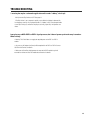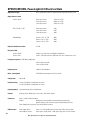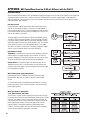
1
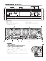
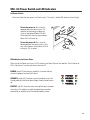
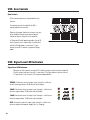
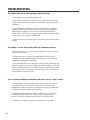
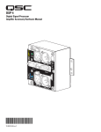
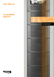
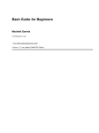
PowerLight 6.0 II
User Manual
*TD-000108-00*
TD-000108-00 rev.A
PowerLight Series
TM
1
IMPORTANT SAFETY INSTRUCTIONS
& EXPLANATION OF SYMBOLS
1- Read these instructions.
2- Keep these instructions.
3- Heed all warnings.
4- Follow all instructions.
5- Do not use this apparatus near water.
6- Clean only with a dry cloth.
7- Do not block any ventilation openings. Install in accordance with QSC Audio Product’s instructions.
8- Do not install near any heat sources such as radiators, heat registers, stoves, or other apparatus (including
amplifiers) that produce heat.
9- Do not defeat the safety purpose of the polarized or grounding-type plug. A polarized plug has two blades with one
blade wider than the other. A grounding-type plug has two blades and a third grounding prong. The wide blade or the
third prong is provided for your safety. If the provided plug does not fit your outlet, consult an electrician for the
replacement of the obsolete outlet.
10- Protect the power cord from being walked on or pinched, particularly at plugs, convenience receptacles, and the
point where they exit the apparatus.
11- Only use attachments/accessories from QSC Audio Products, Inc.
12- Use only with carts, stands, tripods, brackets, interconnecting cables, or software specified by QSC Audio
Products. When moving or transporting using a cart, use caution to avoid injury from tip-over.
13- Unplug the apparatus during lightning storms or when unused for long periods of time.
14- Refer all servicing to qualified personnel. Servicing is required when the apparatus has been damaged in any way,
such as power supply cord or plug is damaged, liquid has been spilled or objects have fallen into the apparatus, the
apparatus has been exposed to rain or moisture, does not operate normally, or has been dropped.
15- When installing equipment into a rack, distribute the units evenly. Otherwise, hazardous conditions may be
created by an uneven weight distribution.
16- Connect the unit only to a properly rated supply circuit.
17- Reliable earthing (grounding) of rack-mounted equipment should be maintained.
18- Maximum operating ambient temperature is 50°C.
The lightning flash with arrowhead symbol within an equilateral triangle is intended to alert the user to the
presence of uninsulated “dangerous” voltage within the product’s enclosure that may be of sufficient
magnitude to constitute a risk of electric shock to humans.
The exclamation point within an equilateral triangle is intended to alert the user to the
presence of important operating and maintenance (servicing) instructions in this manual.
CAUTION
RISK OF ELECTRIC SHOCK
DO NOT OPEN
CAUTION: To reduce the risk of electric shock, do not
remove the cover. No user-serviceable parts inside. Refer servicing to qualified service personnel.
WARNING: To prevent fire or electric shock, do not expose this equipment to rain or moisture.
The PL6.0 II has a serial number located on its side panel, next to the AC cord
entry. It looks like the example, right. Please write the serial number down and
keep for your records. Retain your sales receipt; it is your proof of purchase.
Model: PowerLight 6.0 II
Serial Number: ________________________
Date of Purchase: ______________________
Purchased From: _______________________
© Copyright 2002, QSC Audio Products, Inc.
QSC® is a registered trademark of QSC Audio Products, Inc.
“QSC” and the QSC logo are registered with the U.S. Patent and Trademark Office
Combo is a registered trademark of Neutrik Inc., Lakewood, NJ .
Speakon™ is a registered trademark of Neutrik Inc., Lakewood, NJ
2
TABLE OF CONTENTS
INTRODUCTION
Overview...........................................................................................4
Illustrations.............................................................................5
UNPACKING
Unpacking and Inspection..................................................................................6
What is Included.............................................................................................6
SETUP
Rack Mounting.................................................................................................................6
Cooling Requirements.................................................................................................8
AC Power Requirements..............................................................................9
Operating Mode Selection............................................................................10
CONNECTIONS
Inputs...........................................................................................................12
DataPort....................................................................................14
Power Supply Remote Control....................................................................16
Outputs: Binding Posts...............................................................................17
Outputs: Speakons™.....................................................................................18
USE
Power Switch...........................................................................................19
Power, Standby and Protect LED indicators.............................................19
Gain Controls.............................................................................................20
Signal, -20 dB, -10 dB, and Clip LED indicators........................................................20
Clip Limiters..................................................................................................21
TROUBLESHOOTING...................................................................................22
SPECIFICATIONS............................................................................................................24
APPENDIX
DataPort Pinout..............................................................................................25
QSC PowerWave Technology Overview...........................................................26
WARRANTY INFORMATION .............................................................................................27
HOW TO CONTACT QSC AUDIO PRODUCTS .........................................................27
3
INTRODUCTION- General Overview
Thank you and congratulations on your purchase
of the QSC PowerLight 6.0 II professional power
amplifier. This product represents the state-ofthe-art in power amplification systems for
professional touring, permanent installations,
and other SR (sound reinforcement) applications
requiring high levels of sustained power,
extraordinary audio performance, reduced
weight, and road-proven reliability. To get the
most from your investment, we encourage you
to review this manual carefully.
Part of the advanced technology PowerLight
family of amplifiers, the PowerLight 6.0 II
benefits from QSC’s exclusive PowerWave
switching technology, its DataPort for remote
computer control, and an enhanced design that
provides greater airflow through the chassis—
facilitating cooler, more efficient operation.
QSC PowerWave Technology
QSC’s PowerWave switching power supply
technology provides ample current to the audio
power circuitry by charging the supply rails
180,000 times per second through an ultra-low
impedance circuit. This high-efficiency design
What’s the difference between the “new”
PL6.0 II and the “old” PL6.0? The chart, right,
compares the two. Output power and AC
current consumption are the specifications
that have changed slightly. Output power is 0.9dB at 8 ohms, and -1.04dB at 4 ohms. 2
ohms power remains unchanged. AC current
draw variations are a result of power factor
correction removal and power supply
topology changes. These changes improve
reliability of the amplifier under the most
demanding output conditions.
4
cuts waste heat and boosts reliability while
delivering the added benefits of tighter bass and
transparent highs for a more musical sound.
The PowerLight 6.0 II utilizes an enhanced,
second-generation power supply design. This
new design reduces both EMI (electromagnetic
interference) and the overall weight of the
unit—enabling far greater placement options
when positioning equipment. In the unlikely
event your unit ever requires service, the new
power supply design offers several additional
benefits—including greater ease of service,
resulting in reduced labor time and lower
replacement costs.
Remote Computer Control
The PowerLight 6.0 II also incorporates QSC’s
unique DataPort for remote computer control.
Using QSControl, QSC’s network audio system,
you can monitor and control hundreds of amplifiers simultaneously, as well as perform a wide
range of advanced functions—including event
logging, checking the thermal status of the
amplifier, plus real-time monitoring of loudspeaker opens and shorts.
INTRODUCTION- Illustrations
FRONT PANEL
1- Power switch
2- Power, Standby, and Protect LEDs
3- Cooling air exhaust vents
4- Gain controls
5- Signal, -20 dB, -10 dB, and Clip LEDs
REAR PANEL
1- Cooling air inlet vents
2- Domestic (North America) fixed AC power cord entry
2A- Export IEC-style detachable power cord entry
3- Mode switch (Bridge/Stereo/Parallel)
4- Input connectors (“combo” XLR/TRS and terminal blocks)
5- QSC DataPort Connector (interfaces with QSC accessories)
6- Remote power supply control
7- Output connectors
8- Operating voltage and serial number tag location (side of unit)
5
UNPACKING
Unpacking and Inspection
The PL6.0 II is highly durable and is carefully packaged. We recommend you
inspect the unit carefully after removing it from the packaging, as occasionally
there may be damage due to some unfortunate incident during shipment. Report
any damage to the shipping carrier. We recommend saving the carton and packing
material. It is always a good idea to keep the packaging in case the unit must be
shipped back to your dealer, distributor, or service center. Also note: some freight
companies consider damage claims without the original packing materials invalid.
The QSC shipping box should contain:
1- the PL6.0 II amplifier
2- this Owner’s Manual
3- accessory packet containing:
-rear rack ear mounting kit
-terminal-block connectors for inputs and remote power supply control
-four adhesive feet
SETUP- Rack Mounting
Supporting the Front of the Amplifier
Rack mounting of the amplifier is optional. The PL6.0 II is designed to fit a normal 19-inch width equipment rack.
Secure the front rack ears using four machine screws with washers, as shown below. Verify operating voltage
printed on the serial number plate; it is located on the side panel by the AC cord entry. Once the amplifier is
mounted, it may be difficult to read this information (see p.9).
CAUTION!
To minimize the
risk of injury, we
recommend an
assistant help
support the
amplifier during
rack installation.
When installing
equipment into a
rack, distribute
the units evenly.
Otherwise, hazardous conditions
may be created by
an uneven weight
distribution.
6
SETUP- Rack Mounting
Supporting the Rear of the Amplifier
For mobile and touring use, it is extremely important to support the rear of the amplifier. The chassis and rack
can be damaged if the amplifier is not properly supported. Unless the amplifier is being installed in its final,
fixed location, QSC strongly recommends supporting the rear of the amplifier. Rear rack ears, required hardware, and a separate instruction sheet are included with your amplifier. The Specifications section includes
helpful dimensions for determining rear support locations.
Attaching Rear Rack Ears
Method 1
The amplifier is first installed from
the front of the rack and secured to
the front rack rails. The rear ears are
then secured to the amplifier using
two machine screws. The ears are
secured to the rails using regular
rack hardware.
Method 2
The amplifier is first installed from
the front of the rack and secured to
the front rack rails. Temporarily
secure the rear ears to the rear rack
rails and select the appropriate
mounting position for the “pin”.
Remove the rear ears and install the
locator pins securely. Use of threadlocking is recommended for highvibration installations.
7
SETUP- Cooling Requirements
Cooling Air Inlet and Exhaust Vents
The PL6.0 II has four rear-mounted variablespeed fans. Fan speed is determined by the
temperature of the amplifier’s internal heatsink
assembly.
Cooling air is drawn into the rear of the amplifier
by the fans and exhausts through the front panel.
The temperature of the air exiting the front vents
is a good indicator of how hard the amplifier is
working.
If mounting in a rackmount enclosure, be certain
not to restrict the ability of fresh cooling air to
enter back and exit the front. Do not use in
enclosures with closed or sealed backs or fronts.
The amplifier relies on free air flow in and out of
its vents. Keep the vents free of obstructions and
dust buildup. Periodic inspection of the vents for
dust buildup is recommended. If required, use a
small bristle-brush gently around the vent
openings while the amplifier is running. Do this
outside to avoid blowing dust onto other equipment.
Be certain not to obstruct or block the cooling air vents in any way! Loss of cooling
air flow could result in the amplifier going into thermal shutdown (protective
muting to help cool the amplifier and prevent damage). Keep the vents free of dust
and dirt buildup as airflow will be reduced.
Do not install near any heat sources such as radiators, heat registers, stoves, or
other apparatus that produce heat.
8
SETUP- AC Power Requirements
AC Power
Before connecting the amplifier to the AC
mains, check the serial number plate to
verify operating voltage.
The PL6.0 II is available in 120 or 240 Volt
models. Make sure the AC mains voltage is
the same as specified on the serial number
plate.
120 Volt models have the AC cordset hardwired to the chassis. 240 Volt models have
an IEC-style detachable cordset.
Do not use improper AC
mains voltage! It can
create hazardous conditions and severely damage the amplifier!
AC Power Connection
120 Volt Models
NEMA L5-30 Receptacle
Connect the 30 Amp twist-lock connectors by
orienting the locking L-shaped prong with the
corresponding connector entry, then fully insert
the three prongs. Twist the plug about 1/8 of a
turn clockwise to lock the connector and plug.
240 Volt Models
European 3-conductor Earthing Receptacle
Insert the plug fully into the receptacle.
The PL6.0 II is a very high-power amplifier and as such can demand high current
from the AC service. All connections must be properly rated for reliable operation.
Use of extension cords is discouraged. If extension cords must be used, use only
heavy-duty 10 gauge extension cords that are as short as possible.
9
SETUP- Operating Mode Selection
Operating Mode Selection
The operating Mode selection switch determines
how the inputs are routed to the two amplifier
channels and how the outputs are connected to
the speakers.
The Mode selection switch is located on the rear
panel, left bottom corner. It is a three-position
slide-switch. The switch is recessed to prevent
accidental changes. Change switch positions by
sliding the switch up or down. Operate the
switch with a small, flat-tip screwdriver or
similar tool. Do not use a pencil or other item
that could break off and fall into the chassis.
Stereo Mode
In Stereo Mode, each input signal is
sent to its respective channel. Each
channel has independent gain
control, clip limiting, and output
connection.
To operate in Stereo Mode, set the
Mode Switch to STEREO. Connect
the two input signals and the two
speaker outputs.
10
SETUP- Operating Mode Selection
Parallel Mode
In Parallel Mode, the channel 1 and
channel 2 input connectors are
connected in parallel. Applying an
input signal to either input will drive
both channels. Make sure only one
input signal is applied to the amplifier when operating in Parallel mode.
Each channel still has independent
gain control, clip limiting, and output
connection, just like Stereo Mode.
To operate in Parallel Mode, set the
Mode Switch to PARALLEL. Connect
the single input signal and the two
speaker channels.
Bridge Mode
In Bridge Mode, both output channels are combined into one higher
power channel. The result is one
output with about 4 times the peak
power and about 3 times the sustained power of a single channel.
Use only CH1’s input. Output connections for Bridge Mode are the two
red binding posts. Connection
polarity is clearly marked (CH1 red
binding post= positive, CH2 red
binding post= negative).
To operate in Bridge Mode, set the
Mode Switch to the BRIDGE position.
Connect the single input and the
single speaker channel.
Speakon connectors are not recommended for
Bridge mode use! Use binding post outputs.
Speakons are not wired for Bridge mode output!
11
CONNECTIONS- Inputs
Audio Input Connections
Input connections to the PL6.0 II can be made
with XLR, TRS (1/4-inch), or terminal-block
connectors.
The XLR/TRS connectors are “combo” style; they
accept either XLR or TRS type inputs.
The terminal block connectors are three-pin
“Euro-” (or “Phoenix-”) type. The accessory
packet shipped with your amplifier contains two
of these input connectors.
Each channel’s input connectors are wired in
parallel (example: Ch1’s combo connector is
wired in parallel with CH1’s terminal block
connector). This is useful for daisy-chaining the
input signal to other equipment. If you are using
the “combo” connector for input, the terminalblock connector can be used for daisy-chaining. If
using the terminal-block for input, the “combos”
can be used for daisy-chaining. Remember to
disconnect unused inputs; any input signal on
either input connector will be amplified and
output.
If the Mode Switch is set to PARALLEL, all input
connectors (CH1 and CH2) are connected in
parallel. An input signal applied to any of the four
input connectors will drive the amplifier. Any of
the unused inputs may be used to daisy-chain the
input signal to other equipment. Make sure only
one input signal is applied to the amplifier.
The inputs are electronically balanced. To maintain the benefits of balanced connections, make
all connections using balanced, high-quality cable
and connectors. If balanced inputs are not
available, use an unbalanced-to-balanced converter, such as a “DI” box or proper audio transformer. If the input cables are short and the venue
location free of electrical noise, unbalanced input
connections may be acceptable. This is not the
preferred method, but sometimes necessary. No
damage will be done using unbalanced connections, just a reduction in audio quality and
performance.
Unbalanced connections are prone to noise and
interference pickup as well as ground-loop
induced hum. If your system has noise or hum,
disconnect all amplifier inputs to verify the source
of the noise. If the noise disappears, the noise
source is not the amplifier. Check cabling and
other equipment connections.
Use balanced connections
and high-quality cable and
connectors for best results.
Terminal-block jack
accepts 3-pin terminalblock plugs.
Combo input jack accepts both
XLR and TRS (1/4-inch) plugs.
12
CONNECTIONS- Inputs: XLR, TRS (1/4-inch), and Terminal-block Pinouts
Unbalanced
Balanced
XLR
Jumper
pin 2
pin 2
pin 3
pins 1 and 3
pin 1
TRS (1/4-inch)
phone plug (tip-sleeve)
Terminal-block Connectors
shield
shield
jumper from “–” to shield
13
CONNECTIONS- DataPort (QSControl users only)
What is a DataPort?
The DataPort is a QSC-specific connection used for interfacing amplifiers, amplifier monitoring devices and signal processors. It is typically used in larger-sized installations where
amplifiers may be located far away from system operators. The DataPort interconnects
provide audio inputs to the amplifiers and amplifier operating data (temperatures, power
status, audio power level, etc....) to other QSC equipment, such as the CM16a Amplifier
Network Monitor. Managing all this information and the operation of the amplifiers is QSC’s
QSControl software running on a PC. QSControl primarily handles amplifier tasks, while
another QSC program, Signal Manager, handles Processor configuration.
If you are not using the PL6.0 II with QSControl, QSC DSP-3, QSC DSP-4 or other
QSC DataPort accessory, do not use the DataPort.
DataPort Cables
Use only QSC Audio DataPort Cables for DataPort
connections. Molded-connector DataPort cables
are standard. Premium DataPort cables (made to
order with hand-wired termination) provide
individually shielded audio pairs for the best
possible audio performance. Either type of QSC
DataPort cable is available from QSC’s Technical
Services Group. Computer VGA cables are similar,
but can degrade your audio quality; we do not
recommend their use.
Connecting
Orient the DataPort cable’s male HD-15 plug with
the DataPort receptacle, insert fully, and fingertighten the retaining screws. Do not use tools to
tighten the retaining screws!
If using the DataPort only for control and monitoring of amplifier functions and NOT audio input,
then the audio input may be connected to the
“normal” combo or terminal-block connectors. If
audio inputs are active on both the DataPort and
normal connections, they will be summed,
producing unexpected results.
If connecting a QSC DSP-3 or DSP-4 module to
the PL6.0 II, make sure the DataPort cable
between the amp and the DSP module has pin
#9 removed from either end. See DSP module
documentation for details.
14
CONNECTIONS- DataPort (QSControl users only)
Typical DataPort Application
Refer to QSControl and DataPort Accessory
documentation for connection details.
*Required interface*
Use only QSC Audio
DataPort Cables for
DataPort connections
available from QSC’s
Technical Services
Group..
If amplifier Power
Status is to be controlled with remote
network applications
(QSControl), be sure to
leave the amplifier’s
AC power switch in
the ON position. Place
amplifier in STANDBY
mode using the amplifier network control
software. If the AC
power switch is OFF,
the amplifier will be
unable to respond to
any commands.
15
CONNECTIONS- Power Supply Control (Standby/Enable)
Remotely Controlling the Amplifier’s Power Status
The PL6.0 II provides two methods for remotely
controlling its Power Status:
1- the Power Supply Control connection
2- the DataPort connection (using QSControl)
Two status modes are possible: STANDBY and
ENABLE. Using the Power Supply Control connection, all that is required is a switch and some twoconductor cable. Below is a hookup diagram
outlining the required connections. If using the
DataPort connection, refer to QSControl’s help file
for more information.
NOTE! In order for the amplifier to respond to
STANDBY and ENABLE commands, whether from
the rear-panel connector or DataPort/QSControl,
the AC Power Switch MUST be in the ON position.
If remotely controlling the AC Power Status, turn
the AC Power Switch ON. Place the amplifier in
STANDBY by using the rear-panel Power Supply
Control connections or by using the appropriate
QSControl software, connections, and commands.
Using the Rear Panel Power Supply Control Connector
Included with the PL6.0 II is a 2-pin terminal block
connector for the Power Supply Control. Using
two wires, a S.P.S.T. switch, and the connector,
wire the control as shown in the diagram, right.
When the switch contacts are open, the amplifier
will be operating normally (on).
When the switch contacts are closed, the amplifier will be in Standby mode.
16
Power Supply Control 2-pin connector is located
between the DataPort and CH2’s Speakon.
CONNECTIONS- Outputs: Binding Posts
Connecting the Outputs to the Speakers
Use either the binding post or the Speakon™ output connections. Binding posts are covered on this
page, Speakons on the following page. Note that the PL6.0 II does not support Bridge mode output
from the Speakons (see page 11).
There are two basic speaker connection configurations for the PL6.0 II. Stereo and Parallel operating
modes use two separate output channel connections. Bridge mode uses only one output channel
connection.
Refer to the chart below for connection diagrams. Mode Switch position is shown for reference.
Speakon™ pinout is provided on the following page.
Do not use less than 4-ohm loads in Bridge mode! Note polarity of connections
for Bridge mode. Speakon connections do not support Bridge mode.
Do not use banana-type plugs for connecting to binding posts. They will fail at
the high power levels of this amplifier!
17
CONNECTIONS- Outputs: Speakon™ pinout
Speakon Outputs
The Speakon outputs are for use in Stereo and Parallel operating modes. Minimum speaker
impedance when using Speakon connection is 4-ohms. 2-ohm load-connection to Speakon is not
recommended; output power of this amplifier exceeds Speakon capability at 2-ohms.
The Speakons are wired Pin 1+ = positive, Pin 1- = negative. Below is a diagram for reference.
Speakons are wired for Stereo and Parallel operating modes. Do not use
the Speakons if operating in Bridge mode; use the Binding Posts. Each
Speakon is wired only to its own respective channel (no biamp output on
CH1 like lower power amplifiers).
Do not use 2-ohm loads connected with Speakons!
Use Binding Post connections for 2-ohm loads!
18
USE- AC Power Switch and LED Indicators
AC Power Switch
On the left side of the front panel is the Power switch. The switch is labeled ON, above it and to the right.
To turn the power on: Press in on the
upper portion of the rocker switch. The
amplifier will go through its power-up
cycle; the red-colored Protect LEDs will
illuminate briefly, then the green-colored
Power LEDs will remain on.
To turn the power off: Press in on the
bottom portion of the rocker switch. It may
take a few moments for the Power LEDs to
extinguish. This is normal.
LED Indicators for Power Status
To the right of the Power switch are six LEDs indicating the Power Status of the amplifier. The left column of
LEDs is for channel 1 and the right column for channel 2.
POWER- green LED indicating the amplifier is turned on and connected to a properly functioning AC source.
STANDBY- yellow LED, illuminates when the amplifier is put into
Standby mode by DataPort or Power Supply Remote Control connector.
PROTECT- red LED, illuminates when the amplifier goes into protective muting. This could be caused by shorted wiring or speakers,
overheating, or amplifier failure. See Troubleshooting section.
19
USE- Gain Controls
Gain Controls
A Gain control adjustment is provided for each
channel.
The voltage gain of the amplifier (in dB) is
marked around each control.
Rotating the control clockwise increases the gain
of the amplifier. Rotating the control counterclockwise reduces the gain of the amplifier.
In Stereo and Parallel operating modes (see p.10)
each channel’s gain is adjusted by its respective
control. In Bridge mode, use channel 1’s gain
control; channel 2’s control is ignored in bridge
mode.
USE- Signal Level LED Indicators
Signal Level LED Indicators
Between the Gain controls are eight LEDs indicating input signal level to the amplifier.
The left column indicates channel 1’s input levels. The right column indicates channel
2’s input levels. Each channel’s LEDs operate independently.
SIGNAL- Illuminates when the input signal strength is sufficient
to drive the output above -40 dB relative to full output.
-20 dB- Illuminates when the input signal strength is sufficient to
drive the output above -20 dB relative to full output.
-10 dB- Illuminates when the input signal strength is sufficient to
drive the output above -10 dB relative to full output.
CLIP- Illuminates when the input signal strength is sufficient to
drive the output to the power supply rails (i.e. clipping).
LED indicators.
20
USE- Clip Limiters
Clip Limiters
The PL6.0 II has separate clip limiters for each channel which respond only to actual amplifier clipping.
Amplifier clipping generates internal error signals which cause the Clip Limiter to quickly reduce gain and
minimize the overdrive. To preserve as much of the program dynamics as possible, limiting occurs only
during actual clipping.
The limiter’s on-off switches are front panel mounted and recessed to prevent accidental changes. Each
channel has its own Clip Limiter switch that can be operated independently.
When the push-button-switch is in the “down” or “in” position, the clip limiter is on.
When the push-button-switch is in the “up” or “out” position, the clip limiter is off.
Clip Limiting Tips
Clip limiting reduces extreme overdrive peaks, allowing a higher average signal level without audible
distortion. Increasing the gain with the Clip Limiter engaged, until clipping is again audible, can
double the average output power. Be careful not to exceed the power rating of your speakers.
The Clip Limiter is set to respond as quickly as possible after clipping is detected. On low frequency
material, this may be perceived as a “rubbery” effect. It may be preferable to turn Clip Limiting off,
and let the amp clip occasionally, especially if the speakers are robust.
21
TROUBLESHOOTING
The amplifier won’t turn on when the Power switch is operated• Verify AC power source is providing required voltage.
• Check each end of the power cord. The twist-lock or IEC-type connectors need to be
properly inserted. Inspect the cord for damage. If any damage is found, replace the cord
immediately.
• If using the DataPort and QSC amplifier network control applications, the amplifier
could be in STANDBY mode. Check with the system operator to place the amplifiers in
POWER ON mode. If required, you can check this by temporarily disconnecting the
DataPort cables to each Processor; if the amplifier powers up, then the amplifier network
control was forcing the amp to be in STANDBY mode.
• If using the rear panel Power Supply Control connections, be sure the control’s contacts
are open.
The amplifier “cuts-out” when I really crank it up (intermittent operation)• Make sure the AC power source is rated for the required current! Use only 10-gauge
heavy-duty extension cords.
• If the AC power source is “sagging” (or drooping) under heavy load, the circuit is
overloaded or has other fundamental problems. Use another circuit or have the circuit
checked by a licensed, professional electrician.
• Do not use multiple PL6.0 II’s from the same AC power circuit branch. Momentary, peak
current from the AC line can easily exceed 50 Amps per amplifier. While this is well within
the limits of 30 Amp (continuous) circuits, additional amplifier’s could overload one circuit
branch. Always consult a licensed, professional electrician for verification of proper AC
power distribution in high-power systems.
Can I use some sort of adapter on the power cord so that I can use “regular” outlets?• QSC Audio Products strongly discourages ANY changes in the AC power connections.
Use only NEMA L5-30, 120V, 30 Ampere twist-lock connectors or the 240V cordset
supplied with the amplifier. All supply circuits and AC power receptacles should be rated
for voltage and current printed on the serial number plate.
• Unreliable and potentially dangerous conditions could result from using this product
with improperly rated AC supply circuits. Always consult a licensed, professional
electrician for verification of proper AC power distribution in high-power systems.
• In emergencies, 15A adaptors can be used if full operating levels are avoided.
22
TROUBLESHOOTING
I am using the amp for a subwoofer application and it sounds “rubbery”, what’s up?• Verify that the Clip Limiters are OFF. See page 21.
• The Clip Limiter is set to respond as quickly as possible after clipping is detected. On
low frequency material, this may be perceived as a “rubbery” effect. It may be preferable
to turn Clip Limiting off, and let the amp clip occasionally, especially if the speakers are
robust.
I am trying to use QSC’s DSP-3 or DSP-4 signal processor, but it doesn’t power up when the amp is turned on.
What’s wrong?• Nothing. The PL6.0 II does not supply the required power to the DSP-3 or DSP-4
module.
• An accessory AC adaptor (wall wart) will be required for the DSP-3 or DSP-4. Contact
QSC Technical Services for details.
• Make sure the DataPort cable between the amp and the DSP module has pin #9
removed from either end. See DSP module documentation for details.
23
SPECIFICATIONS- PowerLight 6.0 II Electrical Data
Output Circuit Type
quasi-complementary MOSFET output with multi-step high efficiency circuit
Output Power in watts
20 Hz to 20 kHz
8 ohms per channel
4 ohms per channel
2 ohms per channel
1150 at 0.1% THD
2050 at 0.1% THD
3250 at 0.1% THD
EIA: 1 kHz @ 1% THD
8 ohms per channel
4 ohms per channel
2 ohms per channel
1300
2200
3500
Bridged Mode
16 ohms, 1 kHz, 1% THD
8 ohms, 1 kHz, 1% THD
4 ohms, 1 kHz, 1% THD
2600
4400
7000
Dynamic Headroom at 4 ohms
0.77 dB
Distortion, THD
20 Hz to 20 kHz
20 Hz to 2 kHz
<0.06%: 8, 4, and 2 ohms at 10 dB below rated power
<0.02%: 1150 watts at 8 ohms, 2050 watts at 4 ohms, 3250 watts at 2 ohm
Frequency response at 10 dB below rated power
20 Hz to 20 kHz ±0.15 dB
2 Hz to 50 kHz ±3.0 dB
Damping Factor
>2000 at 1 kHz and below
Noise (unweighted)
107 dB below rated output from 20 Hz to 20 kHz
Voltage Gain
40x (32 dB)
Input Sensitivity
2.4 Vrms (+9.4 dBu) for rated power into 8 ohms
2.3 Vrms (+9.5 dBu) for rated power into 4 ohms
Input Impedance 20 k ohm balanced, 10 k ohm unbalanced
Controls
AC power switch, Mode switch, Gain controls, Clip Limiter switches
Connectors
Inputs: “combo” and terminal-block
Outputs:
binding posts, 60 amp rated, recommend no banana plug usage
Speakon outputs, 1 per channel for Stereo and Parallel operation only
Power Supply Control connector: 2-pin terminal block connector
LED Indicators
Power supply section:
Signal indicator section:
Power “on”- red; Standby- yellow; Protect, red (1 LED for each channel)
Signal- green; -20 dB, yellow; -10 dB, yellow; Clip, red (1 for each channel)
24
Note: Specifications are subject to change without notice.
SPECIFICATIONS- PowerLight 6.0 II Electrical Data
QSControl Control and Monitor Parameters
on/standby, channel gain, mute, polarity, input level, output level, heat sink
temperature, output load sense, clip detect, protect detect, operating Mode
sense (Stereo/Parallel/Bridge)
Cooling
four continuously variable speed fans, rear to front airflow
Amplifier Protection
short circuit, open circuit, thermal, ultrasonic, and RF protection
stable into reactive or mismatched loads
Load Protection
turn-on and turn-off muting, DC fault power supply shut down
Weight
53 lbs (net), 60 lbs (shipping)
Power Requirements
120 Volts AC, 50 to 60 Hertz, 30 Amp NEMA L5-30 receptacle
OR
240 Volts AC, 50 to 60 Hertz, 15 Amp service
Current Consumption
(in amperes, rms)
120 Volts
Current Consumption Notes:
240 Volts
Typical- 1/8 power, pink noise, represents typical program with occasional clipping
Full- 1/3 power, pink noise, represents severe program with heavy clipping
Maximum- continuous sine wave at 1% clipping
Note: Specifications are subject to change without notice.
APPENDIXDataPort Pinout
The DataPort connection is QSC-specific. Information is subject to change.
Pin
1
2
3
4
5
6
7
8
9
10
11
12
13
14
15
Signal Description
Ch. 1 Minus (-) Input Signal
AC Standby Control
V- MON Ch. 1 and Subcode 1
I- MON Ch. 1 and Subcode 2
Clip/Protect Ch. 1
Hard Ground
Ch. 1 Plus (+) Input Signal
Ch. 2 Plus (+) Input Signal
+15V from Amplifier
Data Reference Ground
Ch. 2 Minus (-) Input Signal
Amplifier IDR (Model ID)
V- MON Ch. 2 and Subcode 3
I- MON Ch. 2 and Subcode 4
Clip/Protect Ch. 2
25
APPENDIX- QSC PowerWave Overview & What’s Different with the PL6.0 II
QSC PowerWave
What is PowerWave? PowerWave is QSC's patented power supply technology that not only makes power amplifiers more compact, but
also better sounding. You don’t have to settle for conventional "lead sled" designs with hum, sagging supplies, and backbreaking
weight. PowerWave is a win-win solution, giving you heavyweight audio performance in less than half the size and weight of comparable analog power supply amplifiers.
How does it work?
Conventional power supplies operate at 50 to 60 hertz (50 - 60 cycles per
second). This low frequency requires a massive iron core and hundreds of
turns of copper windings. In fact, a conventional 6000-watt amplifier needs a
transformer that weighs at least 35 pounds, contributing to as much as twothirds of the amplifier's total weight.
The power supply in the PL6.0 II operates at 90 kilohertz (90,000 cycles per
second). By raising the operating frequency of the power supply, the power
transformer and other magnetic devices can be greatly reduced in size and
weight. Peak magnetic flux density is greatly reduced as well. This minimizes
the possibility of magnetic noise coupling between devices or into cables.
Also gone is the infamous “hmmmmmm” of the idling analog power supply.
Acoustic noise from magnetic devices is practically eliminated.
But how does it sound?
Tighter Bass A PowerWave transformer has lower impedance and greater
efficiency because its copper windings are short and thick. In essence, it
provides a “bigger pipe” to get electrical energy to the amp’s output circuitry.
The result? A stiffer power supply that delivers chest-pounding bass.
Cleaner Sound The PowerWave supply in the PL6.0 II charges the rails
180,000 times per second—a vast improvement over 100–120 times per
second in conventional supplies. This high recharge rate minimizes AC ripple
that can degrade sonic quality.
Worried about power supply induced hum?
PowerWave gets rid of it. Completely. The 90-kHz PowerWave supply
eliminates 60 Hz fields that can couple into internal or external audio
circuitry.
So, enjoy the brute power of the 6,000-watt PowerLight 6.0 II, you’ll enjoy
premium performance at less than half the weight of conventional analog
power supply amplifiers!
What’s the difference between the
“new” PL6.0 II and the “old” PL6.0?
The chart, right, compares the two. Output power and AC current consumption are the specifications that have changed slightly. Output power is -0.9dB
at 8 ohms, and -1.04dB at 4 ohms. 2 ohms power remains unchanged. AC
current draw variations are a result of power factor correction removal and
power supply topology changes. These power supply section changes
improve reliability of the amplifier under the most demanding output
conditions. The audio amplifier sections of the PL6.0 II remain unchanged,
assuring the same legendary sound quality of the PL6.0.
26
WARRANTY INFORMATION & HOW TO CONTACT QSC
WARRANTY
(USA only; other countries, see your dealer or distributor)
Disclaimer
QSC Audio Products, Inc. is not liable for any damage to speakers, or any other equipment that is caused by negligence or
improper installation and/or use of this amplifier product.
Product Warranty
QSC Audio Products, Inc. (“QSC”) guarantees its products to be free from defective material and / or workmanship for a period of
three (3) years from date of sale, and will replace defective parts and repair malfunctioning products under this warranty when the
defect occurs under normal installation and use - provided the unit is returned to our factory or one of our authorized service
stations via prepaid transportation with a copy of proof of purchase (i.e., sales receipt). This warranty provides that the examination of the return product must indicate, in our judgment, a manufacturing defect. This warranty does not extend to any product
which has been subjected to misuse, neglect, accident, improper installation, or where the date code has been removed or
defaced. QSC shall not be liable for incidental and/or consequential damages. This warranty gives you specific legal rights, and
you may also have other rights which vary from state to state. This limited warranty is freely transferable during the term of the
warranty period.
HOW TO CONTACT QSC AUDIO PRODUCTS
Mailing address / Adresse postale / Postanschrift / Dirección postal:
QSC Audio Products, Inc.
1675 MacArthur Boulevard
Costa Mesa, CA 92626-1468 USA
Telephone Numbers / Numéros de téléphone / Telefonnummern / Números de teléfono:
Main Number / Numéro principal / Hauptnummer / Número principal
+(714) 754-6175
Sales Direct Line / Ligne directe ventes / Verkauf-Direkt / Línea directo ventas
+(714) 957-7100
Sales & Marketing / Ventes & marketing / Verkauf u. Marketing / Ventas y marketing
(800) 854-4079
(toll-free in U.S.A. only)
(sans frais aux É-U seulement)
(zollfrei nur beim USA)
(sin costo en EE. UU. solamente)
Technical Services Group / Service à la clientèle / Kundendienst / Servicio a la clientela
+(714) 957-7150
(800) 772-2834
(toll-free in U.S.A. only)
(sans frais aux É-U seulement)
(zollfrei nur beim USA)
(sin costo en EE. UU. solamente)
Facsimile Numbers / Numéros de télécopieur / Telefaxnummern / Número de FAX:
Sales & Marketing FAX / Télécopie ventes & marketing / Telefax der Verkauf u. Marketing / FAX ventas y marketing
+(714) 754-6174
Customer Service FAX / Télécopie service à la clientèle / Kundendienst-Telefax / FAX servicio a la clientela
+(714) 754-6173
World Wide Web:
www.qscaudio.com
E-mail:
[email protected]
[email protected]
27
QSC Audio Products, Inc. 1675 MacArthur Boulevard Costa Mesa, California 92626 USA
“QSC” and the QSC logo are registered with the U.S. Patent and Trademark Office.
©2002 QSC Audio Products, Inc.
28