1
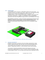
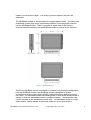
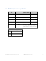
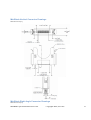
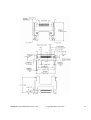
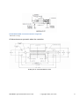
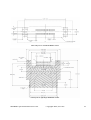
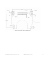
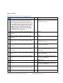
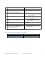
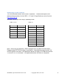
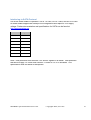
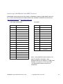
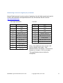
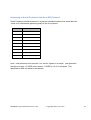
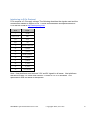
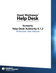
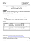
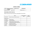
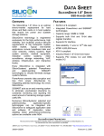
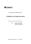
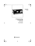
MiniBlade™ SPECIFICATION Revision 1.00 March 6, 2009 IMPORTANT INFORMATION AND DISCLAIMERS The Small Form Factor Special Interest Group, Inc. (SFF-SIG) does not make any warranties with regard to the MiniBlade™ specification (“Specification”) and in particular, neither warrants nor represents that this specification nor any products made in conformance with it will work in the intended manner. Nor does the SFF-SIG assume responsibility for any errors that the Specification may contain or have any liabilities or obligations for damages including, but not limited to, special, incidental, indirect, punitive, or consequential damages whether arising from or in connection with the use of this specification in any way. No representation or warranties are made that any product based in whole or part on this Specification will be free from defects or safe for use for its intended purposes. Any person making, using, or selling such product does so at his or her own risk. THE USER OF THIS SPECIFICATION HEREBY EXPRESSLY ACKNOWLEDGES THAT THE SPECIFICATION IS PROVIDED “AS IS”, AND THAT THE SFF-SIG MAKES NO REPRESENTATIONS, EXTENDS ANY WARRANTIES OF ANY KIND, EITHER EXPRESS OR IMPLIED, ORAL, OR WRITTEN, INCLUDING ANY WARRANTY OF MERCHANTABILITY OR FITNESS FOR ANY PARTICULAR PURPOSE, OR WARRANTY OR REPRESENTATION THAT THE SPECIFICATION OR ANY PRODUCT OR TECHNOLOGY UTILIZING THE SPECIFICATION OR ANY SUBSET OF THE SPECIFICATION WILL BE FREE FROM ANY CLAIMS OF INFRINGEMENT OF ANY INTELLECTUAL PROPERTY, INCLUDING PATENTS, COPYRIGHT AND TRADE SECRETS NOR DOES THE SFF-SIG ASSUME ANY RESPONSIBILITIES WHATSOEVER WITH RESPECT TO THE SPECIFICATION OR SUCH PRODUCTS. THE SFF-SIG DISCLAIMS ALL LIABILITY, INCLUDING LIABILITY FOR INFRINGEMENT OF ANY PROPRIETARY RIGHTS RELATING TO USE OF INFORMATION IN THIS SPECIFICATION. NO LICENSE, EXPRESS OR IMPLIED BY ESTOPPEL, OR OTHERWISE, TO ANY INTELLECTUAL PROPERTY RIGHTS IS GRANTED HEREIN. Designers must not rely upon the absence or characteristics of any features marked “reserved”. The SFF-SIG reserves these for future definition and shall have no responsibility whatsoever for conflicts or incompatibilities arising from future changes to them. Please send comments via electronic mail to [email protected]. Copyright © 2008-2009 Small Form Factor Special Interest Group, Inc. All product names and trademarks, registered trademarks, or service marks are property of their respective owners. MiniBlade Specification Revision 1.00 Copyright 2009, SFF-SIG 2 Revision History Draft Revision Issue Date Comments 1.00 3.06.09 Initial Release MiniBlade Specification Revision 1.00 Copyright 2009, SFF-SIG 3 Table of Contents 1.0 Introduction 5 1.1 General Description 5 1.2 Audience 8 1.3 Related Documents and Organizations 8 2.0 Acronyms and Terms 10 3.0 Connector 11 3.1 Connector and Placement 4.0 11 Power 12 4.1 MiniBlade System Power Specifications Appendix A 13 14 MiniBlade™ Connector Physical Specifications 14 MiniBlade Vertical Connector Drawings 15 MiniBlade Right Angle Connector Drawings 15 Recommended PCB and Stencil Layouts 17 Appendix B 20 MiniBlade Connector Pin Assignments 20 MiniBlade Module Recommended Pin Lengths 21 Interfacing to USB Protocol 22 Interfacing to SATA Protocol 23 Interfacing to MultiMedia Card (MMC) Protocol 24 Interfacing to Secure Digital (SD) Protocol 25 Interfacing to Serial Peripheral Interface (SPI) Protocol 26 Interfacing to PCIe Protocol 27 Table of Figures Figure 1 - MiniBlade Module & MiniBlade Socket (right-angle) Figure 2 - MiniBlade Module MiniBlade Specification Revision 1.00 Copyright 2009, SFF-SIG 5 6 4 1.0 Introduction The MiniBlade system consists of a MiniBlade module and its host socket. The MiniBlade module is a postage stamp-sized, rugged 40-pin card-edge solid-state storage solution intended for embedded system environments. It is complimented by a robust, latching 40-pin socket, available in both vertical and right-angle configurations. Together, the MiniBlade module and MiniBlade socket are known as the MiniBlade storage solution or just MiniBlade technology. This MiniBlade specification contains information (physical and electrical) on the MiniBlade module (the storage device) and the latching MiniBlade socket. This specification affords a design engineer sufficient pertinent information to implement the MiniBlade module storage solution into an embedded system design. Figure 1 - MiniBlade Module & MiniBlade Socket (right-angle) 1.1 General Description MiniBlade technology is intended to meet the storage requirements of highreliability, high-performance and multi-year life-cycle embedded applications. These systems may be deployed in environments that must endure highvibration, temperature extremes, G-forces and other difficult environments. The criteria for developing MiniBlade module technology are small size, mechanically rugged, support an array of common protocols and achieve initial storage capacity of 8GB. As the storage technology matures MiniBlade module MiniBlade Specification Revision 1.00 Copyright 2009, SFF-SIG 5 capacity could become larger. The array of protocol support may also be expanded. The MiniBlade module is encapsulated in a rugged plastic frame. This frame has chamfered corners that act as a polarization feature to ensure proper insertion into the MiniBlade socket. There is a pocket in either side of the frame to accommodate the latches from the MiniBlade socket to ensure a firm insertion. Figure 2 - MiniBlade Module The 40-pin MiniBlade socket is available in a vertical or right-angle configuration. Like the MiniBlade module, the MiniBlade socket is designed to endure environments which require high-reliability, high-performance and long product life cycles. The MiniBlade socket has latching tabs on both sides which provide a secure fit when the MiniBlade module is properly inserted. These latches snap into the pockets on the MiniBlade module shell. The MiniBlade socket is a highspeed socket, able to handle all protocols called out in this specification. MiniBlade Specification Revision 1.00 Copyright 2009, SFF-SIG 6 MiniBlade technology supports the PCIe, SATA, SDIO, MMC and USB interfaces that were originally developed for desktop and mobile environments while leveraging them for use in embedded, medical, instrumentation, communications and industrial applications. A single MiniBlade socket may support more than one protocol simultaneously. While initial MiniBlade modules may support only mass storage, it is the intention of this specification to lay the groundwork for MiniBlade modules that address other I/O capabilities such as wired or wireless networking and GPS. Likely Uses Flash disk drive on single-board computers Operating system boot device Wireless transceivers Likely Applications Industrial control systems Wireless data loggers Process monitoring probes Wearable computers Automotive Medical Military This iteration of MiniBlade technology specifically supports the following I/O connectivity: One (x1) PCIe channel One USB 2.0 channel One SATA 3.0Gbps channel One 8-bit MMC or One 4-bit SDIO channel (Optional SPI is overlaid on this channel). A given MiniBlade module may use one or more of the above interfaces. In the event that a host platform does not include all of the interfaces simultaneously, included interfaces must be clearly declared on all product documentation. MiniBlade Specification Revision 1.00 Copyright 2009, SFF-SIG 7 1.2 Audience This document is written for design engineers that understand the basics of PCstyle peripherals and chipsets. It specifies the electrical and mechanical parameters of the MiniBlade socket and MiniBlade modules in order to ensure multiple sourcing. Since MiniBlade supports high-speed serial bus signals, care must be exercised with respect to best layout practice for high-speed signals. Please reference industry standard organizations’ and special interest groups’ websites listed below for their design and layout recommendations. 1.3 Related Documents and Organizations The MiniBlade specification makes reference to, and is based on the current version of the following specifications and datasheets: MiniBlade Socket Samtec SiliconBlade™ Socket datasheet Samtec, Inc. 520 Park East Boulevard New Albany, IN 47151-1147 USA Phone: +1-812-944-6733 Fax: +1-812-948-5047 http://www.samtec.com MiniBlade Module SiliconSystems SiliconDrive™ Blade Solid-State Drives datasheet SiliconSystems, Inc. 26840 Aliso Viejo Parkway Aliso Viejo, CA 92656 USA Phone: +1-949-900-9400 Fax: +1-949-900-9500 Email: [email protected] http://www.siliconsystems.com MiniBlade Specification Revision 1.00 Copyright 2009, SFF-SIG 8 Interfaces SD Card Association 2400 Camino Ramon, Suite 375 San Ramon, CA 94583 USA Telephone: +1 (925) 275-6615 Fax: +1 (925) 886-4870 E-mail: [email protected] http://www.sdcard.org SATA-IO Administration 3855 SW 153rd Drive Beaverton, Oregon 97006 USA Tel: +1 503-619-0572 Fax: +1 503-644-6708 E-mail: [email protected] http://www.sata-io.org PCI Express Specification PCI-SIG 3855 SW 153rd Drive Beaverton, OR 97006 USA Phone: +1-503-619-0569 Fax: +1-503-644-6708 http://www.pcisig.com USB USB Implementers Forum, Inc. 3855 SW 153rd Drive Beaverton, OR 97006 http://www.usb.org MMC JEDEC 3103 North 10th Street Suite 240 South Arlington, VA 22201-2107 Phone: +1.703.907.7540 Fax: +1.703.907.7583 http://www.jedec.org SPI The SPI bus is a de facto standard, rather than one agreed by any international committee. The reason for this is its essential simplicity. A good reference is http://www.freescale.com/files/microcontrollers/doc/ref_manual/S12SPIV3.pdf MiniBlade Specification Revision 1.00 Copyright 2009, SFF-SIG 9 2.0 Acronyms and Terms ATX-style: Refers to the power supply configuration that allows the computer to be turned off via software. ATX power supplies have two separate five volt signals, one that powers up and down with the system (+5V) and one that remains powered unless the supply is unplugged from the AC source (+5VSB, standby) in order for the system to be capable of waking up from network traffic, keyboard, etc. Lane: A PCI Express link is built around dedicated unidirectional couples of serial (1-bit), point-to-point connections known as "lanes". PCI Express lanes are full-duplex links, meaning that data can be transferred in both directions simultaneously (Tx transmit and Rx receive lines are separate). Lane counts are written with an “x” prefix with “x1” designating a single-lane and ”x4” for a four-lane interface. A x1 (pronounced “by one”) lane is very space efficient compared to the parallel PCI bus that it replaces, with 2.5 times the bandwidth using only five signals. Link: A connection between any two PCI Express devices is known as a "link", and is built up from a collection of one or more lanes. All devices must minimally support single-lane (x1) link. MMC: A memory card form factor that uses SDIO signals. PCIe: Abbreviation for PCI Express. It is a high-speed computer expansion bus designed to replace the general-purpose PCI expansion bus. It is software compatible with PCI in order to be transparent to system software. It is structured around point-topoint full-duplex serial links called lanes. In PCI Express version 1.1 (currently the most common version), each lane operates at a data rate of 250 MB/s in each direction. MiniBlade™ supports two single lanes and one quad lane of data between the baseboard and expansion card. Lane counts are written with an “x” prefix with “x1” designating a single-lane and ”x4” for a four-lane interface. A x1 (pronounced “by one”) lane is very space efficient compared to the parallel PCI bus that it replaces, with 2.5 times the bandwidth using only five signals. Four lanes of 250 MB/s in a x4 link gives a maximum transfer rate of 1 GB/s (250 MB/s x4) in each direction for PCIe 1.1. MiniBlade Specification Revision 1.00 Copyright 2009, SFF-SIG 10 SBC: Abbreviation for Single Board Computer. SBS: Samtec, Inc. SiliconBlade socket . 2X20 positions card edge connector with latches. SDIO: Secure Digital I/O. Secure Digital (SD) is a flash (non-volatile) memory card format developed by Matsushita, SanDisk, and Toshiba for use in portable devices such as digital cameras, handheld computers, PDAs, mobile phones, GPS receivers, and video game consoles. Although SD cards are typically for consumer applications, the interface signals and software are useful for embedded applications when placed on a suitably rugged connector. SMBus: System Management Bus — A simple two-wire bus, derived from I²C and used in the x86 architecture for communication with lowbandwidth devices such as memory sticks, clock generators, and temperature sensors. USB: Universal Serial Bus — It is a serial bus designed to allow peripherals to be connected using a single standardized interface which replaces certain legacy varieties of serial and parallel ports. 3.0 Connector 3.1 Connector and Placement MiniBlade uses a 40-pin card edge connector. Both vertical and right-angle (low profile) sockets are part of the standard. The assignments for the connector pins are shown in Appendix B. MiniBlade can support Generation 1 PCI Express data rates of 2.5Gb/s. Actual test results to demonstrate that it will support data rates of 5Gb/s which is required for PCI Express Generation 2 are not available at the time this specification version was created. In addition, the USB 2.0 data rate of 480Mbps is supported. The Samtec SBS-120-01-S-DV-A-ML socket with a 0.8 mm (0.031-inch) pin pitch is the vertical connector designed specifically for MiniBlade. The right-angle connector part number is SBS-120-01-S-DH-WT-ML . Gold plated pins are mounted in a double row configuration. A total of 40 pins (2X20) are available in the MiniBlade socket. The connector is rugged enough to support many industrial environments. For more information about these connectors, contact Samtec as listed in section 1.3 above. MiniBlade Specification Revision 1.00 Copyright 2009, SFF-SIG 11 Specifications, drawings, and suggested PCB land patterns for the socket and the mating gold-plated PCB traces (card edge fingers) are in Appendix A. Certain chipsets do not support all the interfaces defined on a MiniBlade socket. If an SBC vendor’s board does not or cannot support one or more of the interfaces, it should be clearly marked in the data sheet and technical manuals. 4.0 Power The MiniBlade specification provides for power to be supplied on designated pins. Ground return is supplied through individual pins in each bank populated. The power available to a MiniBlade module is shown below, although the processor board chosen may also limit the total power available to modules somewhat less than the MiniBlade specification. Power requirements in excess of the SBC’s available power specification, or greater than those listed below for the system level definition, must be supplied by a secondary connector on the MiniBlade module itself. In any case, it is up to the system integrator to ensure that the power the processor supplies to the MiniBlade connector(s), the number of modules, and total power consumption for all modules are reconciled and conform to the system available resources. The following tables describe the typical power a host systems should make available for each MiniBlade module in the system. MiniBlade modules that require power in excess of these ratings should document such requirements in the module’s datasheet or user manual. MiniBlade Specification Revision 1.00 Copyright 2009, SFF-SIG 12 4.1 MiniBlade System Power Specifications MiniBlade module type Interface Host-supplied minimum current Voltage tolerance Solid-state storage USB 2.0 200mA +5V ± 10% Solid-state storage SATA 400mA 5V ± 10% Solid-state storage SD 120mA 3.3V ± 10% Solid-state storage MMC 120mA 3.3V ± 10% Solid-state storage PCIe 500mA 3.3V ± 10% Solid-state storage SPI 120mA 3.3V ± 10% Solid-state storage USB 3.0 At the time of publication, this interface has not been built and tested. Please contact SFF-SIG for status of verification Connector Ratings @ +85°C: +3.3V 3A continuous +3VSB 3A continuous +5V 3A continuous MiniBlade Specification Revision 1.00 Copyright 2009, SFF-SIG 13 Appendix A MiniBlade™ Connector Physical Specifications Samtec Part Number SBS-120-01-S-DV-A-ML Materials Housing: Contact: RoHS Compliant: Spec LCP (Liquid Crystal Polymer) Thermoplastic, UL 94-V0 BeCu Yes Contact Finish Socket Interface: Underplate: Spec 30 micro-inches Gold On Contact Area 50 micro-inches Minimum of Nickel Electrical Performance Spec Contact Current Capacity: 3.1 A @ 30°C Temp Rise Solderability Spec Lead-Free Solderable? Yes Processing Temperature: 260°C Produces No Blistering, Distortion, or Discoloration (20 seconds, 3x) 230°C for 60 seconds SMT Lead Coplanarity 0.004” (0.1mm) max MiniBlade Specification Revision 1.00 Copyright 2009, SFF-SIG 14 MiniBlade Vertical Connector Drawings Dimensions in mm [in.] MiniBlade Right Angle Connector Drawings Dimensions in mm [in.] MiniBlade Specification Revision 1.00 Copyright 2009, SFF-SIG 15 MiniBlade Specification Revision 1.00 Copyright 2009, SFF-SIG 16 Recommended PCB and Stencil Layouts Dimensions in mm [in.] All dimensions are symmetric about the centerline. PCB layout for vertical MiniBlade socket MiniBlade Specification Revision 1.00 Copyright 2009, SFF-SIG 17 Stencil layout for vertical MiniBlade socket PCB layout for right angle MiniBlade socket MiniBlade Specification Revision 1.00 Copyright 2009, SFF-SIG 18 Stencil layout for right angle MiniBlade socket MiniBlade Specification Revision 1.00 Copyright 2009, SFF-SIG 19 Appendix B MiniBlade Connector Pin Assignments Pin Notes Pin Notes 1 +3VSB: Optional. Connecting the always-on standby voltage +3VSB to the target electronics allows the module to remain powered during low-power ACPI suspend/standby/sleep states for those SBCs that support ACPI. The module would then be capable of waking up (resuming) the system. Support for optional features must be declared in data sheets and manuals of host boards and MiniBlade modules. If not used, +3VSB must be tied to +3V on the host system. The +3VSB and +3.3V pins must NOT be connected together on a MiniBlade module. Doing so would short-circuit the power supply on an ACPI-enabled SBC. 2 GND: All ground and power pins implemented on MiniBlade modules must be on long gold fingers as defined in the table below. 3 USB3TX+: At the time of publication, this interface has not been built and tested. Please contact SFF-SIG for status of verification. 4 SATA+: 5 USB3TX-: At the time of publication, this interface has not been built and tested. Please contact SFF-SIG for status of verification. 6 SATA-: 7 +3.3V: All ground and power pins implemented on MiniBlade modules must be on long gold fingers as defined in the table below. 8 +5V: All ground and power pins implemented on MiniBlade modules must be on long gold fingers as defined in the table below. 9 USB3RX-: At the time of publication, this interface has not been built and tested. Please contact SFF-SIG for status of verification. 10 PERST# or SDIO_WP: Reserved for future use as a general purpose interrupt 11 USB3RX+: At the time of publication, this interface has not been built and tested. Please contact SFF-SIG for status of verification. 12 BLADE_REQ#: General-purpose interrupt request signal from the MiniBlade module to the host SBC/chipset 13 +3.3V: All ground and power pins implemented on MiniBlade modules must be on long gold fingers as defined in the table below. 14 MMC_SDIO_D0 or SPI_DO: The SPI pin-out is an alternate to SD/MMC and is overlaid in the pin-out. Refer to the table below. 15 GND: All ground and power pins implemented on MiniBlade modules must be on long gold fingers as defined in the table below. 16 MMC_SDIO_D1 or SPI_IRQ: The SPI pin-out is an alternate to SD/MMC and is overlaid in the pinout. Refer to the table below. 17 USB+: 18 MMC_SDIO_D2 19 USB-: 20 MMC_SDIO_D3 or SPI_CS#: The SPI pin-out is an alternate to SD/MMC and is overlaid in the pinout. Refer to the table below. 21 GND: All ground and power pins implemented on MiniBlade modules must be on long gold fingers as defined in the table below. 22 MMC_SDIO_D4 23 A_PETp0 24 MMC_SDIO_D5 MiniBlade Specification Revision 1.00 Copyright 2009, SFF-SIG 20 Pin Notes Pin Notes 25 A_PETn0 26 MMC_SDIO_D6 27 BLADE_PRSNT#: Always grounded by the MiniBlade module. This signal must be on module short pins for PnP (plug-and-play / hot-swap) module applications. 28 MMC_SDIO_D7 29 A_PERp0 30 MMC_SDIO_CMD or SPI_DI: The SPI pin-out is an alternate to SD/MMC and is overlaid in the pinout. Refer to the table below. 31 A_PERn0 32 MMC_SDIO_CLK or SPI_SCLK: The SPI pin-out is an alternate to SD/MMC and is overlaid in the pin-out. Refer to the table below. 33 GND: All ground and power pins implemented on MiniBlade modules must be on long gold fingers as defined in the table below. 34 +5V: All ground and power pins implemented on MiniBlade modules must be on long gold fingers as defined in the table below. 35 A_CLKp 36 SATB- 37 A_CLKn 38 SATB+ 39 PCIe-PRSNT#: Grounded by the MiniBlade module only if PCIe is used to save power and reduce EMI from A_CLK toggling, This signal must be on short pins for PnP (plug-andplay / hot-swap) module applications. 40 GND: All ground and power pins implemented on MiniBlade modules must be on long gold fingers as defined in the table below. Note: Signals are implemented as gold plated card edge signals. An inner layer ground plane must extend to the end of the module underneath the gold fingers. MiniBlade Module Recommended Pin Lengths Signal Type Power and ground BLADE_PRSNT# All other signals MiniBlade Specification Revision 1.00 Pin Length 2.6 mm 1.6mm 2.1 mm Copyright 2009, SFF-SIG 21 Interfacing to USB Protocol The USB standard defines three modes of operation. Detailed descriptions and technical documentation for the USB 1.1, 2.0 and 3.0 specifications can be found at http://www.usb.org. MiniBlade Module pin-outs vary by operating mode. USB 1.1/2.0 USB 3.0 Pin # Signal Pin # Signal 8,34 +5V 3 USB3TX+ 2,15,21,33,40 GND 5 USB3TX- 17 USB+ 8,34 +5V 19 USB- 9 USB3RX+ 27 BLADE_PRSNT# 11 USB3RX- 2,15,21,33,40 GND 17 USB+ 19 USB- 27 BLADE_PRSNT# Note: At the time of publication, USB 3.0 designs have not been built and tested. Please contact SFF-SIG for status of verification. Host platforms must connect 3.3V and 5V signals in all cases. Host platforms that do not supply +3.3VSB must connect +3.3VSB to +3.3V in all cases. This specification does not allow for exceptions. MiniBlade Specification Revision 1.00 Copyright 2009, SFF-SIG 22 Interfacing to SATA Protocol SATA has three modes of operation: SATA 1.5 Gb/s, SATA 3 Gb/s, and SATA 6 Gb/s. All three modes support the same pin-out configuration and require a +5V supply voltage. Further documentation and specifications for SATA can be found at http://www.serialata.org. Pin # Signal 2,15,21,33,40 GND 4 SATA+ 6 SATA- 8,34 +5V 27 BLADE_PRSNT# 36 SATB- 38 SATB+ Note: Host platforms must connect 3.3V and 5V signals in all cases. Host platforms that do not supply +3.3VSB must connect +3.3VSB to +3.3V in all cases. This specification does not allow for exceptions. MiniBlade Specification Revision 1.00 Copyright 2009, SFF-SIG 23 Interfacing to MultiMedia Card (MMC) Protocol MultiMedia Card protocol has two modes of operation: eight-bit (high speed) and fourbit. Further documentation and specifications for the MMC interface can be found at http://www.mmca.org or http://www.jedec.org. 8-bit High Speed MMC 4-bit MMC Pin # Signal Pin # Signal 1 +3VSB 1 +3VSB 2,15,21,33,40 GND 2,15,21,33,40 GND 7,13 +3.3V 7,13 +3.3V 10 PERST# or SDIO_WP 10 PERST# or SDIO_WP 14 MMC_SDIO_D0 or SPI_DO 14 MMC_SDIO_D0 or SPI_DO 16 MMC_SDIO_D1 or SPI_IRQ 16 MMC_SDIO_D1 or SPI_IRQ 18 MMC_SDIO_D2 18 MMC_SDIO_D2 20 MMC_SDIO_D3 or SPI_CS# 20 MMC_SDIO_D3 or SPI_CS# 22 MMC_SDIO_D4 27 BLADE_PRSNT# 24 MMC_SDIO_D5 30 MMC_SDIO_CMD or SPI_DI 26 MMC_SDIO_D6 32 MMC_SDIO_CLK or SPI_SCLK 27 BLADE_PRSNT# 28 MMC_SDIO_D7 30 MMC_SDIO_CMD or SPI_DI 32 MMC_SDIO_CLK or SPI_SCLK MiniBlade Specification Revision 1.00 Note: Host platforms must connect 3.3V and 5V signals in all cases. Host platforms that do not supply +3.3VSB must connect +3.3VSB to +3.3V in all cases. This specification does not allow for exceptions. Copyright 2009, SFF-SIG 24 Interfacing to Secure Digital (SD) Protocol Secure Digital protocol has two modes of operation: four-bit (high speed) and one-bit. Further documentation and specifications for the SD interface can be found at http://www.sdcard.org. 4-bit High Speed SD 1-bit SD Pin # Signal Pin # Signal 1 +3VSB 1 +3VSB 2,15,21,33,40 GND 2,15,21,33, 40 GND 7,13 +3.3V 7,13 +3.3V 10 PERST# or SDIO_WP 10 PERST# or SDIO_WP 14 MMC_SDIO_D0 or SPI_DO 14 MMC_SDIO_D0 or SPI_DO 16 MMC_SDIO_D1 or SPI_IRQ 27 BLADE_PRSNT# 18 MMC_SDIO_D2 30 MMC_SDIO_CMD or SPI_DI 20 MMC_SDIO_D3 or SPI_CS# 32 MMC_SDIO_CLK or SPI_SCLK 27 BLADE_PRSNT# 30 MMC_SDIO_CMD or SPI_DI 32 MMC_SDIO_CLK or SPI_SCLK MiniBlade Specification Revision 1.00 Note: Host platforms must connect 3.3V and 5V signals in all cases. Host platforms that do not supply +3.3VSB must connect +3.3VSB to +3.3V in all cases. This specification does not allow for exceptions. Copyright 2009, SFF-SIG 25 Interfacing to Serial Peripheral Interface (SPI) Protocol Serial Peripheral Interface protocol is a pseudo-standard synchronous serial data link. There is no international governing body for the SPI protocol. Pin # Signal 1 +3VSB 2,15,21,33,40 GND 7,13 +3.3V 14 MMC_SDIO_D0 or SPI_DO 16 MMC_SDIO_D1 or SPI_IRQ 20 MMC_SDIO_D3 or SPI_CS# 27 BLADE_PRSNT# 30 MMC_SDIO_CMD or SPI_DI 32 MMC_SDIO_CLK or SPI_SCLK Note: Host platforms must connect 3.3V and 5V signals in all cases. Host platforms that do not supply +3.3VSB must connect +3.3VSB to +3.3V in all cases. This specification does not allow for exceptions. MiniBlade Specification Revision 1.00 Copyright 2009, SFF-SIG 26 Interfacing to PCIe Protocol PCIe requires a 3.3V supply voltage. The following describes the signals used and the connections needed to support PCIe. Further documentation and specifications for PCIe can be found at http://www.pcisig.com. Pin # Signal 1 +3VSB 2,15,21,33,40 GND 7,13 +3.3V 8,34 +5V 10 PERST# or SDIO_WP 23 A_PETp0 25 A_PETn0 27 BLADE_PRSNT# 29 A_PERp0 31 A_PERn0 35 A_CLKp 37 A_CLKn 39 PCIe-PRSNT# Note: Host platforms must connect 3.3V and 5V signals in all cases. Host platforms that do not supply +3.3VSB must connect +3.3VSB to +3.3V in all cases. This specification does not allow for exceptions. MiniBlade Specification Revision 1.00 Copyright 2009, SFF-SIG 27