1
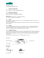
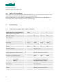
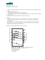
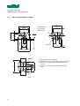
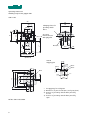
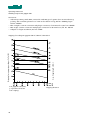
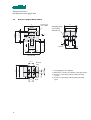
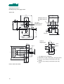
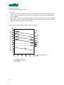
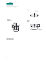
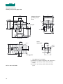
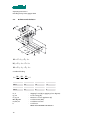
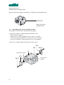
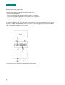
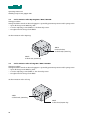
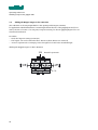
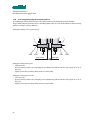
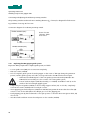
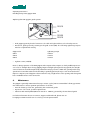
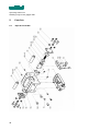
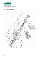
USER MANUAL
HANDLING COMPONENTS
Gripper GPP
BA-100035
starting from serial number 425533
english, edition 06/2007
Operating instructions
Handling Components gripper GPP
Table of contents
1.
Important Information ...................................................................................................................3
1.1.
Manufacturer explanation .......................................................................................................................3
1.2.
Purpose .....................................................................................................................................................3
1.3.
Hazards .....................................................................................................................................................3
1.4.
Additional information.............................................................................................................................3
1.5.
Validity of the User Manual .....................................................................................................................4
2.
Technical Data ................................................................................................................................4
2.1.
Technical data for gripper GPP-1 / GPPI-1 / GPP-ISO-1.......................................................................4
2.2.
Dimension diagram GPP-1 / GPPI-1 .......................................................................................................6
2.3.
Technical data for gripper GPP-2 / GPPI-2 / GPP-ISO-2.......................................................................9
2.4.
Dimension diagram GPP-2 / GPPI-2 .....................................................................................................11
2.5.
Technical data for gripper GPP-3 / GPPI-3 / GPP-ISO-3.....................................................................14
2.6.
Dimension diagram GPP-3 / GPPI-3 .....................................................................................................16
2.7.
Definition and calculation ......................................................................................................................19
3.
Commissioning .............................................................................................................................20
3.1.
Installed position ....................................................................................................................................20
3.2.
Mounting.................................................................................................................................................20
3.3.
Operating modes closed / open depressurized..................................................................................21
3.4.
Maintenance of gripping force..............................................................................................................22
3.5.
Stroke Limitation when Opening GPP / GPPI / GPP-ISO ...................................................................24
3.6.
Stroke Limitation when Closing GPP / GPPI / GPP-ISO .....................................................................24
3.7.
Opening and Closing Rate ....................................................................................................................25
3.8.
Shifting the gripper jaws in the X direction..........................................................................................25
3.9.
Shifting the Gripper Fingers in the Y Direction ...................................................................................26
3.10.
Connecting and Setting the Proximity Switches .................................................................................27
3.11.
Replacing the GPP gripper guide system ............................................................................................28
4.
Maintenance .................................................................................................................................29
5.
Parts lists ......................................................................................................................................30
5.1.
Exploded view GPP................................................................................................................................30
5.2.
Parts lists GPP- gripper..........................................................................................................................31
5.3.
Exploded view GPPI...............................................................................................................................32
5.4.
Parts lists GPPI........................................................................................................................................33
1
Operating instructions
Handling Components gripper GPP
5.5.
Exploded view GPP-ISO ........................................................................................................................34
5.6.
Parts lists GPPI........................................................................................................................................35
6.
Environmental Compatability and Disposal ............................................................................... 36
2
Operating instructions
Handling Components gripper GPP
1.
Important Information
EC Declaration of Conformity (see MRL Appendix II A)
1.1.
Manufacturer explanation
Rules and standards complied with:
Machinery guidelines 89/392/EWG, 91/368/EWG
Manufacturer:
Montech AG, Gewerbestrasse 12 CH-4552 Derendingen
Tel. +41 32 681 55 00, Fax +41 32 682 19 77
1.2.
Purpose
GPP grippers are used where workpieces have to be regularly gripped internally or externally, for
material handling purposes.
Under all circumstances attention must be paid to the performance limits, as given in the technical data in
these instructions.
1.3.
Hazards
The use of GPP grippers in an installation is only permissible when they are guarded by MOVING, ISOLATING PROTECTIVE DEVICES as per EN 292-2, para.4.2.2.3. Failure to comply with this protective
measure can result in injury due to fingers being squeezed, for example.
1.4.
Additional information
The aim of the present User Manual is to enable users to employ gripper GPP correctly and safely. Should
further information be required in relation to your particular application, please contact the manufacturer.
When reordering User Manuals, it is essential to quote the reference number, the product name and
serial number.
This document can be obtained from our homepage www.montech.com.
Nameplate
Reference number
Product name
Serial number
Montech AG
Management
U. D. Wagner
3
C. Wullschleger
Operating instructions
Handling Components gripper GPP
1.5.
Validity of the User Manual
Our products are continually updated to reflect the latest state of the art and practical experience. In line
with product developments, our User Manuals are continually updated.
Every User Manual has an order number (e.g. BA-100035) and an edition number (e.g. 06/2007). The order number and the addition number are shown on the title page.
2.
Technical Data
2.1.
Technical data for gripper GPP-1 / GPPI-1 / GPP-ISO-1
Gripping distance = stroke Gripping
distance (total travel of jaws)
[mm]
Gripping distance adjustable
opening / closing
GPP
GPPI
GPP-ISO
6
6
6
yes
yes
yes
12
12
Piston diameter
[mm]
12
Gripping force F1, F2
[N]
see gripping force diagram
Mass moment of inertia Jz
[kgcm2]
0.87
0.87
0.87
[mm]
±0.005
±0.005
±0.005
Operating pressure
[bar]
3-6
Weight
[kg]
0.25
0.26
0.28
1)
Repetability
air,oiled or unoiled,filtered to 5µm,
dew point <6°C
Operating medium
Pneumatic connection
2)
Check on end position open / closed
3)
Opening / Closing time
4)
détecteur de proximité inductif
[s]
Thread for mounting positioners
Ambient:
Temperatue
[°C]
0.015
0.015
0.015
4xM3
4xM3
4xM3
10–50
Rel. humidity
5% - 85% (without condensation)
Air purity
atmosphère d’atelier normale
Warranty
2 ans à partir de la date de livraison
Maintenance
see maintenance
Mounting position
any
Material
aluminium, steel, bronze, plastic
Noise level
4
[dBA]
<60
Operating instructions
Handling Components gripper GPP
1)
2)
3)
4)
Variation of the gripped end position in 100 successive strokes without the effect of additional, external
forces
GPP M5 (supply see accessories
GPPI pneumatic connection via Quick-Set® clamping collar
GPP-ISO with adjustable M5 exhaust throttles, pluggable, Ø 4 mm hose included in the scope of supply
See accessories
Measured at maximum stroke, between 3 and 6 bar, without spring
Accessories:
– Inductive proximity switch PNP, 6.5 mm dia. with LED, proof against short circuit and wrong
polarity, with a switching clearance of 2 mm and a cable 2 m long, Ref.No. 508842; plug-in
Ref.No. 508843.
– M5 “straight” screw-in connection with plug-in connection for Ø 4 mm hose, Ref. No. 504928
– M5 “angle” screw-in connection with plug-in connection for Ø 4 mm hose, Ref. No. 506319
– Adapter for finger attachment, Ref. No. 39025
max. finger length L [mm ]
Gripping force per gripper finger F1, F2 [N]
Gripping force diagram gripper GPP-1 / GPPI-1 / GPP-ISO-1
Gripping direktion
B in gripped state (mm)
p = pneumat. Pressure
Fed = Spring
5
Operating instructions
Handling Components gripper GPP
2.2.
Dimension diagram GPP-1 / GPPI-1
44
50
Clamping sleeve
for proximity
switch Ø 6.5
40
2
3
28 GPP
32 GPPI
Y
4
36 GPP
40 GPPI
4
40 GPP
ø40 GPPI
X
F 1*
L*
12.5
min. 25.5 1)
max. 31.5
F 2* F 2*
133)
M3x5 (4x)
13 2)
35.5
2.25
F 1*
B min. 50/max. 56 1)
(Stroke 6)
26 ±0.02
10 ±0.02
26 ±0.1
3H7x5
Hole
6
51
66
20 ±0.1
Thread
M4x8
* See gripping force diagram
1) Dimension of jaws closed (min.) and open (max.)
2) Position of proximity switch when jaws fully
closed
3) Position of proximity switch when jaws fully
open
Operating instructions
Handling Components gripper GPP
Air supply per
mounting part
View Y
GPPI
View X
Gripping jaw
14.25
M3x6
11.5 ±0.05
M3x6
7.5
4.75
4.5
24.5
Ref.No. GPP-1 41357
Ref.No. GPPI-1 41358
7
M3x5
View Y
GPP
9.5
4H8
31
Air supply M5
Operating instructions
Handling Components gripper GPP
GPP-1-ISO
50
44
3
Clamping sleeve for
proximity switch
Ø 6.5
32
20 ±0.01
Air supply
Exhaust throttles
with plug Ø 4
4
3
41
5
ø25 g6
2
40
13 3)
X
min. 25.5 1)
max. 31.5
F 1*
F2 * F2 *
L*
12.5
M3x5 (4x)
13 2)
35.5
2.25
F1 *
B min. 50/max. 56 1)
(Stroke 6)
View X
Gripping jaw
14.25
4H8
M3x6
ø6 h6
14.1 14.1
51
66
78
M5x9
14.1 14.1
Ref.No. GPP-1-ISO 39814
8
11.5 ±0.05
20 ±0.01
M3x5
M3x6
7.5
4.75
24.5
* See gripping force diagram
1) Dimension of jaws closed (min.) and open (max.)
2) Position of proximity switch when jaws fully
closed
3) Position of proximity switch when jaws fully
open
Operating instructions
Handling Components gripper GPP
2.3.
Technical data for gripper GPP-2 / GPPI-2 / GPP-ISO-2
Gripping distance = stroke Gripping distance (total travel of jaws)
[mm]
Gripping distance adjustable
opening / closing
GPP
GPPI
GPP-ISO
12
12
12
yes
yes
yes
20
20
Piston diameter
[mm]
20
Gripping force F1, F2
[N]
see gripping force diagram
Mass moment of inertia Jz
[kgcm2]
4.3
4.3
4.3
[mm]
±0.02
±0.02
±0.02
Operating pressure
[bar]
3-6
Weight
[kg]
0.68
0.68
0.72
Repetability
1)
air,oiled or unoiled,filtered to 5µm,
dew point <6°C
Operating medium
Pneumatic connection
2)
Check on end position open / closed
3)
Opening / Closing time
4)
Induktive proximity switches
[s]
Thread for mounting positioners
Ambient:
Temperatue
[°C]
0.045
0.045
0.045
4xM3
4xM3
4xM3
10–50
Rel. humidity
5% - 85% (without condensation)
Air purity
Normal workshop atmosphere
Warranty
2 years from the date of delivery
Maintenance
see maintenance
Mounting position
any
Material
aluminium, steel, bronze, plastic
Noise level
1)
2)
3)
4)
9
[dBA]
<60
Variation of the gripped end position in 100 successive strokes without the effect of additional, external
forces
GPP M5 (for connection, see accessories)
GPPI pneumatic connection via Quick-Set® clamping collar
GPP-ISO with adjustable M5 exhaust throttles, pluggable, Ø 4 mm hose included in the scope of supply
See accessories
Measured at maximum stroke, between 3 and 6 bar, without spring
Operating instructions
Handling Components gripper GPP
Accessories:
– Inductive proximity switch PNP, 6.5 mm dia. with LED, proof against short circuit and wrong
polarity, with a switching clearance of 2 mm and a cable 2 m long, Ref.No. 508842; plug-in
Ref.No. 508843.
– M5 “straight” screw-in connection with plug-in connection for Ø 4 mm hose, Ref. No. 504928
– M5 “angle” screw-in connection with plug-in connection for Ø 4 mm hose, Ref. No. 506319
– Adapter for finger attachment, Ref. No. 39026
max. finger length L [mm]
Gripping force per gripper finger F1, F2 [N]
Gripping force diagram gripper GPP-2 / GPPI-2 / GPP-ISO-2
B in gripped state (mm)
p = pneumat. Pressure
Fed = Spring
10
Gripping direction
Operating instructions
Handling Components gripper GPP
2.4.
Dimension diagram GPP-2 / GPPI-2
Housing contour of GPPI
75
42 GPP
49 GPPI
55
3
Y
4
3
50 GPP
57 GPPI
4
40 GPP
ø40 GPPI
61
Clamping sleeve
for proximity
switch Ø 6.5
1.2
12.5
17.5 3)
L*
X
M3x6 (4x)
max. 501)
min. 38
F 1*
F 2*
F2 *
17.5 2)
46
4.5
F1 *
B min. 75/max. 87 1)
(Stroke 12)
26 ±0.02
Thread
20 ±0.1
3H7x5
26 ±0.1
11
Hole
10 ±0.02
68
72
M4x8
* * See gripping force diagram
1) Dimension of jaws closed (min.) and open (max.)
2) Position of proximity switch when jaws fully
closed
3) Position of proximity switch when jaws fully
open
Operating instructions
Handling Components gripper GPP
Air supply per
mounting part
View Y
GPPI
View X
Gripping jaw
View Y
GPP
21
5H8
12
M4x5
M4x6
18 ±0.05
M4x6
4.5
6
Air supply M5
37
Ref.No. GPP-2 41359
Ref.No. GPPI-2 41361
12
46
12.5
Operating instructions
Handling Components gripper GPP
GPP-2-ISO
61
75
ø25 g6
55
5
3
Clamping sleeve for
proximity switch Ø
6.5
3
45
54
Air supply
Exhaust throttles
4
3
with plug Ø 4
1.2
12.5
max. 50 1)
min. 38
F1 *
F2 *
F 2*
17.5 2)
17.5 3)
L*
X
M3x6 (4x)
4.5
46
F 1*
B min. 75/max. 87 1)
(Stroke 12)
Viewt X
Gripping jaw
20 ±0.01
ø6 h6
14.1 14.1
68
72
95
M4x5
18 ±0.05
M4x6
12.5
6
37
14.1 14.1
13
5H8
M4x6
M5x12
Ref.No. GPP-2-ISO 39817
21
* See gripping force diagram
1) Dimension of jaws closed (min.) and open (max.)
2) Position of proximity switch when jaws fully
closed
3) Position of proximity switch when jaws fully
open
Operating instructions
Handling Components gripper GPP
2.5.
Technical data for gripper GPP-3 / GPPI-3 / GPP-ISO-3
Gripping distance (total travel of jaws)
[mm]
Gripping distance adjustable
opening / closing
GPP
GPPI
GPP-ISO
20
20
20
yes
yes
yes
25
25
Piston diameter
[mm]
25
Gripping force F1, F2
[N]
see gripping force diagram
Mass moment of inertia Jz
[kgcm2]
14
14
14
[mm]
±0.03
±0.03
±0.03
Opening pressure
[bar]
3-6
Weight
[kg]
1.32
1.42
1.42
Repeatability
1)
air,oiled or unoiled,filtered to 5µm,
dew point <6°C
Operating medium
Pneumatic connection
2)
Check on end position open / closed
3)
Opening / Closing time
4)
induktive proximity switches
[s]
Thread for mounting positioners
Ambient:
Temperature
[°C]
0.12
0.12
0.12
4xM4
4xM4
4xM4
10-50
Rel. humidity
5% - 85% (without condensation)
Air purity
normal workshop atmosphere
Warranty
2 years from the date of delivery
Maintenance
see maintenance
Mounting position
any
Material
aluminium, Steel, bronze, plastic
Noise level
1)
2)
3)
4)
14
[dBA]
<60
Variation of the gripped end position in 100 successive strokes without the effect of additional, external forces
GPP M5 connection, see accessories
GPPI pneumatic connection via Quick-Set® clamping collar
GPP-ISO M5 connection, see accessories
See accessories
Measured at maximum stroke, between 3 and 6 bar, without spring
Operating instructions
Handling Components gripper GPP
Accessories:
– Inductive proximity switch PNP, 6.5 mm dia. with LED, proof against short circuit and wrong
polarity, with a switching clearance of 2 mm and a cable 2 m long, Ref.No. 508842; plug-in
Ref.No. 508843.
– M5 “straight” screw-in connection with plug-in connection for Ø 4 mm hose, Ref. No. 504928
– M5 “angle” screw-in connection with plug-in connection for Ø 4 mm hose, Ref. No. 506319
– Adapter for finger attachment, Ref. No. 39027
max. finger length L [mm]
Gripping force per gripper finger F1, F2 [N]
Gripping force diagram gripper GPP-3 / GPPI-3 / GPP-ISO-3
Gripping direction
B in gripped state (mm)
p = pneumat. Pressure
Fed = Spring
15
Operating instructions
Handling Components gripper GPP
2.6.
Dimension diagram GPP-3 / GPPI-3
Clamping sleeve
for proximity
switch Ø 6.5
100
55 GPP
60 GPPI
70
3
Y
3
63 GPP
68 GPPI
4
40 GPP
ø40 GPPI
76
4
1.6
M4x9 (4x)
16
L*
X
min. 50.5 1)
max. 70.5
F1*
F2 *
F2 *
22 3)
22 2)
60
5
F1 *
B min. 100/max. 120 1)
(Stroke 20)
26 ±0.02
Thread
20 ±0.1
10 ±0.02
78
83
M4x8
26 ±0.1
3H7x5
Hole
16
* See gripping force diagram
1) Dimension of jaws closed (min.) and open (max.)
2) Position of proximity switch when jaws fully
closed
3) Position of proximity switch when jaws fully
open
Operating instructions
Handling Components gripper GPP
View Y
GPPI
View X
Gripping jaw
Air supply per
mounting part
View Y
GPP
27.25
5H8
23.5 ±0.05
M4x7
7.25
17.5 17.5
49.5
Ref.No. GPP-3 41363
Ref.No. GPPI-3 41365
17
21.5
M4x7
M4x7
4
62
Air supply M5
Operating instructions
Handling Components gripper GPP
76
100
Clamping sleeve for
proximity switch
Ø 6.5
3
55
64
5
ø25 g6
70
3
3
Air supply M5
4
1.6
M4x9 (4x)
16
min. 50.5 1)
max. 70.5
F1 *
F2 *
F2 *
22 3)
22 2)
L*
X
60
5
F1 *
B min. 100/max. 120 1)
(Stroke 20)
20 ±0.01
View X
Gripping jaw
27.25
5H8
M4x7
M4x7
M4x7
23.5 ±0.05
ø6h6
14.1 14.1
78
83
M5x12
7.25
17.5 17.5
49.5
14.1 14.1
Ref.No. GPP-3-ISO 45094
18
Air supply M5
* See gripping force diagram
1) Dimension of jaws closed (min.) and open (max.)
2) Position of proximity switch when jaws fully
closed
3) Position of proximity switch when jaws fully
open
Operating instructions
Handling Components gripper GPP
2.7.
Definition and calculation
Mx
Mx
Lx
Lx
Fy
Fy
F1
Ly
F1
F2
Lz
Mz
F2
Fz
Fz
Mx = Fz ⋅ L y + Fy ⋅ L z
M y = F 1,2 ⋅ L z + F z ⋅ L x
M z = F 1,2 ⋅ L y + F y ⋅ L x
Combined loading
b=
Mx My Mz
+
+
≤1
K1 K2 K3
K1
K2
K3
GPP-1
2.3
1.9
1.9
GPP-2
9
7.5
7.5
GPP-3
22
18
18
F1, 2
Fy, Fz
Lx, Ly, Lz
Mx, My, Mz
K1, K2, K3
b
19
:
:
:
:
:
:
Gripping force [N] (as gripping force diagram)
Forces acting [N]
Distances of force application [m]
Load moments [Nm]
Load limit constants
Load factor:
MUST NOT EXCEED THE VALUE 1
Operating instructions
Handling Components gripper GPP
3.
Commissioning
3.1.
Installed position
GPP-grippers can be installed in any position.
3.2.
Mounting
The GPP/GPPI grippers can be mounted quickly and easily by QUICK-SET® components.
If no QUICK-SET® components are used, the GPP can be screwed on direct
Attachment using bolts or QUICK-SET®
SLL-55
GPP
GPPI attachment using QUICK-SET® for internal compressed air feed
GPPI
SRR-40
20
Operating instructions
Handling Components gripper GPP
GPP-ISO attachment, gripper attachment in compliance with ISO-9409-1-A40
GPP-ISO
Gripper fixed as per
ISO-9409-1-A40
3.3.
Operating modes closed / open depressurized
The spring is not installed, but is included with each gripper.
Conversion procedure to “Gripper depressurized when closed”
– Depressurize the gripper.
– Remove the four screws (250/G) and remove the cover (70/G).
– Insert the spring (250, supplied loose) in the bottom of the piston.
– Fix the cover (70/G) to casing (10) with the four screws (250/G).
Conversion to “Gripper depressurized when closed / open”
70/G
250
250/G
10
proximity switches
70/O
250/O
250
21
Compressedair input
Operating instructions
Handling Components gripper GPP
Conversion procedure to “Gripper depressurized when open”
– Depressurize the gripper.
– Remove the four screws (250/O) and remove the cover (70/O).
– Insert the spring (250, supplied loose) in the bottom of the piston.
– Fix the cover (70/O) to casing (10) with the four screws (250/O).
3.4.
Maintenance of gripping force
To secure the gripping force, e.g. in the event of an emergency stop, we recommend the use of the stop
valve ref. no. 46582. Compared with the use of springs to secure the gripping force, this has the advantage of maintaining the gripping force at 100%.
Diagram of connections for non-return throttle valve
Load
Two-way valve
If a single-action load is fitted, the connection B1 must be closed.
22
Operating instructions
Handling Components gripper GPP
Internal air supply GPP-1 to GPP-3 and GPP-3-ISO
B
C1
C2
A
(Gewinde M5)
(Gewinde M5
B
Internal air supply GPPI-1 to GPPI-3
C1
C2
B
A
B
Internal air supply GPP-1-ISO and GPPI-2-ISO
C1
C2
A
B
For all size
– If C1 is pressurized, the jaws move in direction A
– If C2 is pressurized, the jaws move in direction B
23
Do not use grippers
without non-return
throttle valve!
Operating instructions
Handling Components gripper GPP
3.5.
Stroke Limitation when Opening GPP / GPPI / GPP-ISO
Setting procedure
Setting should be carried out when the gripper is opened by pneumatic pressure and/or spring action.
– Open blocking screw 380/O by 360°.
– Turn the adjusting screw (390/O) to the desired position.
– Re-tighten the blocking screw 380/O.
Stroke Limitation when Opening
380/O
Innensechskant,
Socket-head, 2,5mm key
390/O
Socket-head, 2,5mm key
3.6.
Stroke Limitation when Closing GPP / GPPI / GPP-ISO
Setting procedure
Setting should be carried out when the gripper is opened by pneumatic pressure and/or spring action.
– Open blocking screw 380/S by 360°.
– Turn the adjusting screw (390/S) to the desired position.
– Re-tighten the blocking screw 380/S.
Stroke Limitation when Closing
380/S
Socket-head, 2,5mm key
390/S
Socket-head, 2,5mm key
24
Operating instructions
Handling Components gripper GPP
3.7.
Opening and Closing Rate
The grippers GPP-1 to GPP-3, GPPI-1 to GPPI-3 and GPP-3 ISO contain internal throttle holes for safety.
The integrated throttles protect the gripping jaws against abrupt opening and closing, are non adjustable
, and eliminate the need for an external throttle.
The grippers GPP-1 ISO and GPP-2 ISO require a non-return throttle valve,
which must be set so that the gripping jaws do not cause a hard impact either
when opening or closing.
3.8.
Shifting the gripper jaws in the X direction
(The X direction is the axis of the opening or closing movement) For applications which demand exact
concentricity between the axis of the gripped part and, for instance, the axis of rotation of a rotary unit, it
may be necessary for the two gripping jaws to be corrected in the X direction.
Setting
– Undo screw (320).
– The two jaws can now be shifted synchronously in the X axis (the distance C and the Y direction
are retained).
– When the exact position of the clamping fingers has been determined, tighten screw (320) with
the torque Md given in the following table.
∆X max.
Md
GPP-1, GPPI-1, GPP-1 ISO
0,6 mm
2 Nm
GPP-2, GPPI-2, GPP-2 ISO
0,8 mm
4 Nm
GPP-3, GPPI-3, GPP-3 ISO
0,8 mm
4 Nm
Shifting the gripper jaws in the X direction
320
Thread for positioner
X
X
SF
DX
25
C
DX
Operating instructions
Handling Components gripper GPP
3.9.
Shifting the Gripper Fingers in the Y Direction
(The Y direction is the axis perpendicular to the opening and closing movements)
For applications which demand exact concentricity between the axis of the gripped part and, for instance, the axis of rotation of a rotary unit, it may be necessary for the two gripping fingers to be corrected in the Y direction.
Procedure
– Undo the finger mounting screws (SF)
– The fingers can now be shifted in the Y direction (the X direction is retained).
– ∆Y max. represents the screw play in the through hole found in the attached finger.
Shifting the Gripper Fingers in the Y Direction
320
DY
Thread for positioner
DY
SF
26
Operating instructions
Handling Components gripper GPP
3.10.
Connecting and Setting the Proximity Switches
The inductive proximity switches may not be set before the stroke limitation has been finalized.
The proximity switches used must have a switching distance (Sn) of 2 mm, be intended for flush mounting
and have a casing 6.5 mm in diameter.
Setting procedure (Jaws open/closed)
i2
LED
i1
430
360
Jaws closed
360
430
LED
Jaws open
Setting procedure (Jaws open)
– Open the jaws.
– Insert proximity switch (i1) in clamping sleeve (430) and together with the sleeve push in as far as
the stop.
– Lightly secure the proximity switch with set-screw (360).
Setting procedure (Jaws closed)
– Close the jaws.
– Insert proximity switch (i2) in clamping sleeve (430) and together with the sleeve push in as far as
the stop.
– Lightly secure the proximity switch with set-screw (360).
27
Operating instructions
Handling Components gripper GPP
Connecting and adjusting the inductive proximity switches
The proximity switches used must have a switching distance (Sn) of 2 mm, be designed for flush mounting, and have a hous-ing -Ø of 6.5 mm.
Connection diagram for inductive proximity switch
Direct current (DC)
braun : brown
schwarz : black
blau : blue
Direct current (DC)
3.11.
Replacing the GPP gripper guide system
Important: Always replace the complete guide system, incl. balls!
– Loosen grub screw (340); do not unscrew completely.
– Remove screws (120/60)
– Lift off complete guide system from the gripper. In the event of damage during the guarantee
period, seal the guide system, incl. balls, in a bag and send to the Montech national agent.
– Lubricate all individual parts of the new guide system with Paraliq P460 (Art. No.
504721) before installing. For the content of the new guide system,
– Fasten inside end piece (120/30; assembly 1 or 120/20; assemblies 2 and 3) on the
inside of the left and right gripping jaws.
– Temporarily fix rail guides (120/10) on the housing support surface (10). To do this, completely
screw in the screws (120/60) and loosen by 0.5 a turn.
– Insert gripping jaw with end pieces (120/30 or 120/20) facing inwards. Ensure that the roller (60)
comes to rest on the slide (30) in the oblique groove of the gripping jaw.
– Push gripping jaws by hand outwards to the open position so that the drive unit (piston slide, 30)
also moves.
– Introduce balls and then mount the end pieces on the outside (120/20).
28
Operating instructions
Handling Components gripper GPP
Replacing the GPP gripper guide system
120/10
10
120/20
120/10
– Push gripping jaws by hand a few times to the left and right and then to both end positions.
– Pretension guide system by screwing in the grub screws (340). The following tightening torques
must be complied with exactly.
Gripper side
GPP-1
GPP-2
GPP-3
tightening torque
10 Ncm
12 Ncm
15 Ncm
– Tighten screws (120/60).
Note: If, during operation of the GPP gripper with compressed air, impacts or clearly audible impact noises occur, for example due to heavy gripping fingers and high opening and closing speeds, the straight
screw connections should be replaced by exhaust throttles, by means of which the opening and closing
speed can be somewhat reduced. The throttling is optimally performed only to such an extent that the
impacts or impact noises disappear. This measure has only a slight effect on the opening and closing time
but considerable effect on the service life.
4.
Maintenance
The gripper is generally maintenance-free up to 10 mio. cycles]. We recommend the following preventative maintenance to ensure optimum performance of the unit:
– Periodic cleaning of the unit, particularly the mechanical guide.
– Inspection of the seals, possible replacement
– Lubricate with Paraliq P460 (Montech article no. 504721), particularly the mechanical guide
For further information about our services, support and downloads, please visit our
homepage at www.montech.com or contact your local representative.
29
Operating instructions
Handling Components gripper GPP
5.
Parts lists
5.1.
Exploded view GPP
30
Operating instructions
Handling Components gripper GPP
5.2.
No.
Parts lists GPP- gripper
Sym.
Part
Ref.No.
Material
Size 1
Size 2
Size 3
◘
GPP- gripper
41357
41359
41363
Various
10
◊
Casting GPP
48735
48731
48708
Aluminium
20
●
Set of jaws
56895
56905
56906
Steel
30
◊
Piston
38006
37927
38049
Bronze
40
◊
Slide-valve
43802
40913
40914
Steel
50
◊
Roller
43803
–
–
Steel
50
●
Needle bearing
–
503597
503597
Steel
60
◊
Cover GPP
38012
37933
38054
Aluminium
70
◊
Jib
47641
47641
47641
POM
80
●
Clamping sleeve
42009
42009
42009
POM
100
●
Seal kit for
507249
507250
507251
NBR
100/10
◊
O-Ring
504819
501466
505031
NBR
100/20
◊
O-Ring
503109
503140
503803
NBR
110
●
Comp. spring
503011
503142
503334
Steel
120
◊
Ribbed washer 3.2
502363
502363
502363
Steel
130
◊
Chhd screw M3x8
501603
501603
501603
Steel
140
◊
Set-screw M5
501913
501914
501915
Steel
150
◊
Set-screw M3
501887
501889
501888
Steel
160
◊
Set-screw M3
501884
501889
501890
Steel
170
◊
Set-screw M5
501908
501910
506005
Steel
180
◊
Chhd screw M3
501603
501621
501622
Steel
190
◊
Cyl. pin ø3x10h6
502020
–
–
Steel
190
◊
Bearing pin
–
40915
40915
Steel
200
◊
Prot. stopper
503536
503536
503536
Polyurethan
● These are wearing parts and available ex stock.
◊ Not available ex stock individually (upon request)
◘ Price-listed items available ex stock
31
Operating instructions
Handling Components gripper GPP
5.3.
32
Exploded view GPPI
Operating instructions
Handling Components gripper GPP
5.4.
No.
Parts lists GPPI
Sym.
Part
Ref.No.
Material
Size 1
Size 2
Size 3
◘
GPPI- gripper
41358
41361
41365
Various
10
◊
Casting GPPI
41185
41186
41187
Aluminium
20
●
Set of jaws
56895
56905
56906
Steel
30
◊
Piston
38006
37927
38049
Bronze
40
◊
Slide-valve
43802
40913
40914
Steel
50
◊
Roller
43803
–
–
Steel
50
●
Needle bearing
–
503597
503597
Steel
60
◊
Deckel GPPI
38012
37933
38054
Aluminium
70
◊
Jib
47641
47641
47641
POM
80
●
Clamping sleeve
42009
42009
42009
POM
100
●
Seal kit for
507249
507250
507251
NBR
100/10
◊
O-ring
504819
501466
505031
NBR
100/20
◊
O-ring
503109
503140
503803
NBR
110
●
Comp. spring
503011
503142
503334
Steel
120
◊
Ribbed washer 3.2
502363
502363
502363
Steel
130
◊
Chhd screw M3x8
501603
501603
501603
Steel
140
◊
Set-screw M5
501913
501914
501915
Steel
150
◊
Set-screw M3
501887
501889
501888
Steel
160
◊
Set-screw M3
501884
501889
501890
Steel
170
◊
Set-screw M5
501908
501910
506005
Steel
180
◊
Chhd screw M3
501603
501621
501622
Steel
190
◊
Cyl. pin ø3x10h6
502020
–
–
Steel
190
◊
Bearing pin
–
40915
40915
Steel
210
◊
Set-screw M3x3
501885
501885
501885
Steel
220
◊
Set-screw M3
501886
501885
501885
Steel
● These are wearing parts and available ex stock.
◊ Not available ex stock individually (upon request)
◘ Price-listed items available ex stock
33
Operating instructions
Handling Components gripper GPP
5.5.
34
Exploded view GPP-ISO
Operating instructions
Handling Components gripper GPP
5.6.
No.
Parts lists GPPI
Sym.
Part
Ref.No.
Material
Size 1
Size 2
Size 3
◘
GPP-ISO- gripper
39814
39817
45094
Various
10
◊
Casting GPP-ISO
39815
39818
45093
Aluminium
20
●
Set of jaws
56895
56905
56906
Steel
30
◊
Piston
38006
37927
38049
Bronze
40
◊
Slide-valve
43802
40913
40914
Steel
50
◊
Roller
43803
–
–
Steel
50
●
Needle bearing
–
503597
503597
Steel
60
◊
Deckel GPPI
40195
40196
38054
Aluminium
70
◊
Jib
47641
47641
47641
POM
80
●
Clamping sleeve
42009
42009
42009
POM
90
◊
Seal kit for
39816
39816
39816
Steel
100
●
Seal kit for
507249
507250
507251
NBR
100/10
◊
O-ring
504819
501466
505031
NBR
100/20
◊
O-ring
503109
503140
503803
NBR
110
●
Comp. spring
503011
503142
503334
Steel
120
◊
Ribbed washer 3.2
502363
502363
502363
Steel
130
◊
Chhd screw M3x8
501603
501603
501603
Steel
140
◊
Set-screw M5
501913
501914
501915
Steel
150
◊
Set-screw M3
501887
501889
501888
Steel
160
◊
Set-screw M3
501884
501889
501890
Steel
170
◊
Set-screw M5
501908
501910
506005
Steel
180
◊
Chhd screw M3
501603
501621
501622
Steel
190
◊
Cyl. pin ø3x10h6
502020
–
–
Steel
190
◊
Bearing pin
–
40915
40915
Steel
200
◊
Prot. stopper
-
-
503536
Polyurethan
230
◊
Non-return throttle valve M5x4 505023
505023
-
brass
● These are wearing parts and available ex stock.
◊ Not available ex stock individually (upon request)
◘ Price-listed items available ex stock
35
Operating instructions
Handling Components gripper GPP
6.
–
–
–
–
–
–
–
Environmental Compatability and Disposal
Materials used
Aluminium
Steel
Bronze
Acrylnitrile butadiene rubber (NBR to ISO 1629)
Polyoxymethylene (polyacetal) (POM)
Paraffinic mineral oil, synthetic hydrocarbnon oil
Surface treatment
– Anodizing of aluminium
– Surface hardening of alloy steels
– Blackening of steel
– Shaping processes
– Machining of Al, Steel, POM, Bronze
– Moulding of NBR seals
Emissions during operation
– None
– When the equipment is used with oiled air, it is advisable to return the exhaustair to atmosphere
through an oil filter or separator.
Disposal
Grippers which cannot be used any more should be recycled, not as complete units, but dismantled to
components and disposed of according to the type of material. The kind of material used for each part is
shown in the spare parts list. Material which cannot be recycled should be appropriately disposed of.
36