1
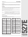
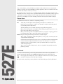
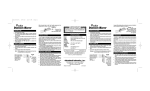
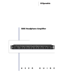
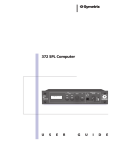
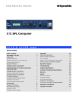
527E User’s Guide
527E Voice Processor
Table of Contents
Introduction
1
Chapter 2
Operator Safety Summary
2
Chapter 3
Fast Setup
3
Chapter 4
Front Panel Overview
5
Chapter 5
Rear Panel Overview
7
Chapter 6
Using the 527E
8
Chapter 7
Applications
11
Chapter 8
Troubleshooting
13
Chapter 9
Specifications
14
Chapter 10
Block Diagram
16
Chapter 11
Warranty & Service
17
Appendix A
Declaration of Conformity
19
527E
Chapter 1
Rev A.00, 1 September, 1999
Symetrix part number 53527-0A00
Subject to change without notice.
©1999, Symetrix, Inc. All right reserved.
Symetrix is a registered trademark of Symetrix, Inc.
Mention of third-party products is for informational
purposes only and constitutes neither an endorsement nor
a recommendation. Symetrix assumes no responsibility
with regard to the performance or use of these products.
Under copyright laws, no part of this manual may be
reproduced or transmitted in any form or by any means,
electronic or mechanical, including photocopying,
scanning, recording or by any information storage and
retrieval system, without permission, in writing, from
Symetrix, Inc.
i
14926 35th Ave. West
Lynnwood, WA 98037 USA
Tel (425) 787-3222
Fax (425) 787-3211
Email: [email protected]
Chapter 1
Introduction
The Symetrix 527E traces its heritage back to the Symetrix 528, the first signal processor specifically
designed for voice applications. Revered as the rackmount equivalent of a studio console strip, the
classic 528E is still the most widely-used voice processor in the broadcast industry. To this
benchmark design, we added new controls and connections, and we refined it according to the
needs of installed sound applications. The result: An ideal product for installations requiring great
sounding key microphones. When used on announcement mics in stadiums and gymnasiums,
wireless and lapel mics in church systems, and paging mics in acoustically challenging
environments, the 527E provides voice-optimized processing from the company than invented it.
Simply stated, the 527E consists of a high-quality microphone preamp coupled to a three-band
parametric equalizer, high and low pass filters, and a dynamic range processor.
The dynamic range processor combines an interactive compressor/limiter and a downward
expander. Typically, the downward expander helps reduce background noise as well as the artifacts
of close miking. The compressor/limiter gives you overall control over the dynamic range of the
output signal and helps maintain a high overall signal level.
The filter section of the 527E features tunable low cut and high cut filters. These 12 db per octave
filters allow the user to remove objectionable low frequency noises, such as rumble and muddiness,
and high frequency noises, such as sibilance and air conditioning noise.
The three-band parametric equalizer is a reciprocal-curve design. Each band is connected in series
with the next to ensure that each filter band sums with its neighbors smoothly.
We recommend that you read this manual from cover to cover. Somewhere between the confines of
the two covers you should find the answers to most (98%) of your questions. Should you have
any comments or questions, please do not hesitate to contact us at the numbers/addresses below.
Your calls are always welcome.
Phone:
(425) 787-3222
Fax:
(425) 787-3211
Email:
[email protected]
Website:
www.symetrixaudio.com
EXPANDER
INPUT
MIC GAIN
MIX
COMPRESSOR
THRESHOLD
THRESHOLD
VOICE
PROCESSOR
CLIP
60
MIC
LINE
GR
-25
3
3
-10
2
CLIP
6
6
0
12
9
-10
20
BYP
0
12 -40
+20
1
10
-20 -15
FILTERS
BYPASS
IN
BYPASS
GAIN
X:1
GR
20
OUTPUT
RATIO
(dB)
527E
LOW CUT (Hz)
0
22
EXP/COMP
+15
MID EQ
HIGH EQ
FREQUENCY
BANDWIDTH
CUT/BOOST
FREQUENCY
BANDWIDTH
CUT/BOOST
FREQUENCY
BANDWIDTH
CUT/BOOST
(Hz)
(OCT)
(dB)
Hz
OCT
dB
Hz
OCT
dB
160
1.5
0
2.5K
1.5
0
6.8K
1.5
18K
0
42K
5K
8
LOW EQ
HIGH CUT (Hz)
50
115
6
260
3K
65K
16
500
.3
4
-15
+15
160
6.3K
.3
4
-15
+15
680
22K
.3
4
EQ/
FILTERS
MUTE
-15
+15
POWER
Front panel
PROCESSOR
527E VOICE
OUTPUTS
MUTE CONTROL
LINE
AC INPUT
15 WATTS
MAXIMUM
FABRIQUÉ AUX E.-U. PAR SYMETRIX INC., LYNNWOOD, WASHINGTON.
RÉFÉREZ TOUTE RÉPARATION À UN TECHNICIEN QUALIFIÉ.
INPUTS
LINE
NC
-15dB
0dB
MANUFACTURED BY SYMETRIX INC.
LYNNWOOD, WA USA
THIS PRODUCT CONTAINS NO
USER SEVICEABLE PARTS.
LINE
MIC
LINE
MIC
ON
OFF
MIC PAD PHANTOM
Rear panel
1
527E
The 527E accepts both mic and line inputs. The microphone input uses a balanced transformerless
design. It works with any phantom-powered condenser microphone or any low-impedance microphone having a balanced, floating output. The line input also uses a balanced transformerless
design and its matched resistors permit the 527E to attain a high, wideband, CMRR (common-mode
rejection ratio). Multistage RFI filters prevent radio frequency interference problems. The 527E’s
output section can drive balanced loads at line or mic levels.
Operator Safety Summary
Equipment Markings
CAUTION
RISK OF ELECTRIC SHOCK
DO NOT OPEN
TO REDUCE THE RISK OF FIRE OR
SHOCK DO NOT EXPOSE
WARNING: ELECTRIC
THIS EQUIPMENT TO RAIN OR MOISTURE
DE CHOC ELECTRIQUE
AVIS: RISQUE
NE PAS OUVRIR
SEE OWNERS MANUAL. VOIR CAHIER D’INSTRUCTIONS.
No user serviceable parts inside. Refer servicing to qualified service personnel.
Il ne se trouve a l’interieur aucune piece pourvant entre reparée l’usager.
S’adresser a un reparateur compétent.
The lightning flash with arrowhead symbol within an
equilateral triangle is intended to alert the user of the
presence of uninsulated “dangerous voltage” within
the product's enclosure that may be of sufficient
magnitude to constitute a risk of electric shock to
persons. The exclamation point within an equilateral
triangle is intended to alert the user of the presence of
important operating and maintenance (servicing)
instructions in the literature accompanying the
product (i.e. this manual).
Caution To prevent electric shock, do not use the
polarized plug supplied with the unit with
any extension cord, receptacle, or other
outlet unless the blades can be fully
inserted.
Terms
527E
Several notational conventions are used in this
manual. Some paragraphs may use Note, Caution,
or Warning as a heading. Certain typefaces and
capitalization are used to identify certain words.
These are:
Note
Caution
Warning
CAPITALS
Boldface
Identifies information that needs
extra emphasis. A Note generally
supplies extra information to help
you to better use the 527E.
Identifies information that, if not
heeded, may cause damage to the
527E or other equipment in your
system.
Identifies information that, if
ignored, may be hazardous to your
health or that of others.
Controls, switches or other markings
on the 527E’s chassis.
Strong emphasis.
Important Safety Instructions
Please read and keep these instructions. Heed
and follow all warnings and instructions. Install
in accordance with the manufacturer’s instructions.
Power Source This product is intended to
operate from a power source that does not apply
more than 120V rms between the power supply
conductors or between either power supply
conductor and ground. A protective ground
2
Chapter 2
connection, by way of the grounding conductor
in the power cord, is essential for safe operation.
Grounding The chassis of this product is
grounded through the grounding conductor of
the power cord. To avoid electric shock, plug the
power cord into a properly wired receptacle
before making any connections to the product. A
protective ground connection, by way of the
grounding conductor in the power cord, is
essential for safe operation. Do not defeat the
safety purpose of the grounding plug. The
grounding plug has two blades and a third
grounding prong. The third prong is provided for
your safety. When the provided plug does not fit
your outlet, consult an electrician for replacement
of the obsolete outlet.
Danger from Loss of Ground If the protective
ground connection is lost, all accessible conductive parts, including knobs and controls that may
appear to be insulated, can render an electric
shock.
Proper Power Cord Use only the power cord
and connector specified for the product and your
operating locale. Use only a cord that is in good
condition. Protect the power cord from being
walked on or pinched, particularly at plugs,
convenience receptacles, and the point where
they exit from the apparatus.
Operating Location Do not operate this equipment under any of the following conditions:
explosive atmospheres, in wet locations, in
inclement weather, improper or unknown AC
mains voltage, or if improperly fused. Do not
install near any heat source such as radiators,
heat registers, stoves, or other apparatus
(including amplifiers) that produce heat. Unplug
this apparatus during lightning storms or when
unused for long periods of time.
Stay Out of the Box To avoid personal injury (or
worse), do not remove the product covers or
panels. Do not operate the product without the
covers and panels properly installed. Only use
accessories specified by the manufacturer. Clean
only with a damp cloth.
User-serviceable parts There are no user
serviceable parts inside the 527E. In case of
failure, refer all servicing to the factory. Servicing
is required when the 527E has been damaged in
any way, such as when a power supply cord or
plug is damaged, liquid has been spilled or
objects have fallen into the apparatus, the
apparatus has been exposed to rain or moisture,
does not operate normally, or has been dropped.
Fast Setup
Chapter 3
Fast Setup
Follow these instructions to get your 527E up-and-running as quickly as possible. The intent of
this section is fast setup. If you need something clarified, then you’ll find the answer elsewhere in
this manual.
Connections
Connect your input source to the appropriate XLR or Euroblock connector. Connect the 527E’s
output to line-level input using the line-level XLR or Euroblock output connector. If you need to
feed a mic-level input, use the mic-level XLR output connector.
If you are using a condenser microphone, refer to “Phantom Powering Condenser Microphones” in
Chapter 6 before depressing the PHANTOM POWER switch.
Caution
Failure to connect the 527E to the proper AC mains voltage may cause fire and/or
internal damage. There are no user serviceable parts inside the chassis. Refer all
service to qualified service personnel or to the factory.
Warning
Lethal voltages are present inside the chassis. There are no user serviceable parts
inside the chassis. Refer all service to qualified service personnel or to the factory.
Connect the AC input to an AC power source of the proper voltage and frequency, as marked on the
rear of the unit.
Settings for Initial Setup
Set the controls and switches on the front and rear panel as follows:
Se tting
Front Pane l
Control
Se tting
MIC GAIN
12 o'clock
EQ Low
FREQUENCY
160 (12 o'clock)
MIX
12 o'clock
EQ Low
BANDWIDTH
1.5 octaves (12 o'clock)
Expander
THRESHOLD
0 (max CW)
EQ Low
CUT/BOOST
0 (12 o'clock)
Compressor
Threshold
- 10 (12 o'clock)
EQ Mid
FREQUENCY
2.5K (12 o'clock)
Compressor
RATIO
2:1 (12: o'clock)
EQ Mid
BANDWIDTH
1.5 octaves (12 o'clock)
GAIN
0 (12 o'clock)
EQ Mid
CUT/BOOST
0 (12 o'clock)
BYPASS
EXP/COMP
IN
EQ High
FREQUENCY
2.5K (11 o'clock)
EQ High
BANDWIDTH
1.5 octaves (12 o'clock)
EQ High
CUT/BOOST
0 (12 o'clock)
BYPASS
EQ/FILTERS
IN
LOW CUT
22 (10 o'clock)
HIGH CUT
18K (3 o'clock)
527E
Front Pane l
Control
3
The 527E’s controls and switches are now set
according to the preceding section. The 527E
should now pass signal. The OUTPUT LEVEL LED
display and the POWER LED should be illuminated.
Depending upon the signal levels, the
compressor’s gain-reduction display may be
illuminated.
Refining Your Settings
Temporarily put the Exp/Comp and EQ sections
into bypass mode, set the MIC GAIN control so that
the OUTPUT LED display indicates a signal level
between -10 and 0 VU. The CLIP LED should almost
never illuminate.
Use the downward expander to reduce background
noise and/or mouth noises. Set the THRESHOLD
control to allow low level speech sounds to pass
while still blocking unwanted sounds which are at a
lower level than the lowest-level speech audio.
Re ar Pane l
Output
Se tting
Connect to input of
console, tape recorder,
etc.
If you wish to use the
Mute Control mute control, please
refer to Chapter 6.
Line Input
Connect line- level
source here.
Mic Input
Connect microphone
here.
Mic Pad
0dB (Out)
Phantom
Power
Depress if mic requires
phantom powering.
Use the threshold control to vary the amount of
gain reduction, as indicated on the compressor’s
gain-reduction display. Generally, 3 to 6 dB is
sufficient, unless you are using a low compression ratio (below 2:1), or you want a special effect.
Pick a ratio suited to the task at hand: low ratios and low thresholds for unobtrusive level control,
medium ratios for overall level control and consistency, high ratios (> 8:1) for limiting or in-yourface sorts of sounds.
527E
The frequency settings given will work well with male voices. For women, the low-EQ range shifts
up to 200 or 300Hz, the mid-EQ range shifts up to 3-5 kHz.
If you are using a microphone that exhibits proximity effect when you close-talk it, then you’ll
probably need to reduce (cut) the bass (low) response somewhat. 3-6 dB should be fine (don’t do
this if you want a big, ballsy sound). A bit of mid-EQ will help make voices cut and seem loud. The
high-EQ adds brightness and intimacy.
If you are using a microphone that has minimal proximity effect (like the ElectroVoice RE-20), then
you’ll probably need to increase (boost) the bass response somewhat. 3 to 6 dB should do the job.
The same mid- and high- EQ recommendations given previously still apply.
For many applications, setting the output GAIN control at 0 dB (12:00 o’clock) works fine. If you are
adding a bunch of EQ (which tends to cause an overall level increase), then you may need to
decrease the GAIN setting. On the other hand, if you are using a fair amount of compression, you
may need to add some gain to compensate for the level lost in compression. Pick a setting that
gives you enough signal downstream, yet still keeps the CLIP LED from illuminating. The output
display is peak responding, so you can’t quite set levels as if it were a VU meter (which responds
more slowly).
The output CLIP LED monitors the output stage. Large amounts of boost and/or high signal levels
can cause CLIP indications. If this occurs, lower the signal level via the GAIN control.
4
Chapter 4
Front Panel Overview
EXPANDER
INPUT
MIC GAIN
MIX
COMPRESSOR
THRESHOLD
THRESHOLD
VOICE
PROCESSOR
GR
-25
3
3
6
20
60
MIC
LINE
-10
2
CLIP
20
0
12 -40
22
EXP/COMP
MID EQ
HIGH EQ
FREQUENCY
BANDWIDTH
CUT/BOOST
FREQUENCY
BANDWIDTH
CUT/BOOST
FREQUENCY
BANDWIDTH
CUT/BOOST
(Hz)
(OCT)
(dB)
Hz
OCT
dB
Hz
OCT
dB
160
1.5
0
2.5K
1.5
0
6.8K
1.5
0
18K
42K
5K
8
LOW EQ
HIGH CUT (Hz)
50
115
-10
9
BYP
LOW CUT (Hz)
0
0
6
12
CLIP
GAIN
X:1
GR
FILTERS
BYPASS
IN
BYPASS
OUTPUT
RATIO
(dB)
527E
+20
1
10
-20 -15
+15
6
260
3K
65K
16
500
.3
4
-15
+15
160
6.3K
.3
4
-15
+15
680
22K
.3
4
-15
+15
EQ/
FILTERS
MUTE
POWER
Input
MIC GAIN
Sets the gain of the mic preamp for best compromise between signal-to-noise ratio
and headroom.
MIX
Selects between the Mic input and Line input, or allows a mix of both inputs.
CLIP LED
Monitors mic inputs for clipping. Illuminates 3 dB below the actual clip point.
MUTE LED
Lights when the output of the 527E has been muted by a remote switch connected to
the 527E’s rear panel MUTE CONTROL Euroblock connector.
EXPANDER THRESHOLD
Sets the threshold level for the downward expander. Signals below this
threshold are downward expanded (reduced in level).
COMPRESSOR THRESHOLD
Sets the threshold level for the compressor. Signals above this
threshold cause gain reduction in the compressor.
COMPRESSOR RATIO
Sets the compression ratio of the compressor. This determines the
amount by which above-threshold signals will be compressed.
DOWNWARD
EXPANDER
LED Display
Indicates the amount of downward expander activity (gain reduction) at
any instant in time.
COMPRESSOR
LED Display
Indicates the amount of compressor activity (gain reduction) at any
instant in time.
527E
Downward Expander / Compressor
Output Section
GAIN
Sets the overall gain of the 527E’s output over a ±15 dB range. The actual adjustment
point is in the expander/compressor’s VCA, which is pre-EQ.
OUTPUT LED
Display
Indicates the peak output level of the527E relative to the balanced output. 0 VU
on the display corresponds to +4dBu at the balanced output. For unbalanced
applications, the actual output level is 6 dB lower than that shown by the display.
Note
The 527E’s mic output will have an output level of -36dBu when the display
indicates 0 VU.
Bypass
EXP/COMP
IN/BYPASS Switch
Defeats the downward expander/compressor. This is not a hard-wire
bypass.
EQ/FILTERS
IN/BYPASS Switch
Disengages the EQ and Filter section when set to the Bypass (Out)
position. This is a hardwire bypass.
5
Filters
LOW CUT
Selects the cutoff frequency of the LOW CUT FILTER (variable from 6 Hz to 260 Hz).
This filter will uniformly pass frequencies above the cutoff frequency.
HIGH CUT
Selects the cutoff frequency of the HIGH CUT FILTER (variable from 3kHz to 65 kHz).
This filter will uniformly pass frequencies below the cutoff frequency.
Parametric EQ Low
FREQUENCY
Varies the center frequency of the low-frequency equalizer from 16Hz to 500 Hz.
BANDWIDTH
Varies the bandwidth of the low-frequency equalizer from 0.3 to 4 octaves.
(Q=4.8 to 0.27).
CUT/BOOST
Sets the degree of boost or cut; ±15 dB.
Parametric EQ Mid
FREQUENCY
Varies the center frequency of the mid-frequency eq from 160 Hz to 6300 Hz.
BANDWIDTH
Varies the bandwidth of the mid-frequency eq from 0.3 to 4 octaves.
(Q=4.8 to 0.27).
CUT/BOOST
Sets the degree of boost or cut; ±15 dB.
Parametric EQ High
Varies the center frequency of the equalizer from 680 Hz to 22 kHz.
BANDWIDTH
Varies the bandwidth of the high-frequency equalizer from 0.3 to 4 octaves.
(Q=4.8 to 0.27).
CUT/BOOST
Sets the degree of boost or cut; ±15 dB.
527E
FREQUENCY
POWER LED
6
Indicates the presence of AC power.
Chapter 5
Rear Panel Overview
VOICE
527E PROCESSOR
OUTPUTS
MUTE CONTROL
LINE
AC INPUT
15 WATTS
MAXIMUM
LINE
FABRIQUÉ AUX E.-U. PAR SYMETRIX INC., LYNNWOOD, WASHINGTON.
RÉFÉREZ TOUTE RÉPARATION À UN TECHNICIEN QUALIFIÉ.
SERIAL NUMBER
INPUTS
LINE
NC
-15dB
0dB
MANUFACTURED BY SYMETRIX INC.
LYNNWOOD, WA USA
THIS PRODUCT CONTAINS NO
USER SEVICEABLE PARTS.
MIC
LINE
MIC
ON
OFF
MIC PAD PHANTOM
[Please send us the completed warranty card.]
AC POWER INPUT IEC-power connector. Connect only to appropriate AC power source. Refer to
rear-panel marking for correct AC source voltage.
Outputs
LINE OUTPUT
XLR connector or a Euroblock connector. Balanced, line-level output.
Connections are:
XLR
Pin 1
Pin 2
Pin 3
Euroblock
+
-
Ground
High
Low
To feed an unbalanced load, connect the Ground (shield) side to Pin 1 (ground)
only, and the Hot (center conductor) side to Pin 2 (+).
MIC OUTPUT
XLR connector. Balanced, mic-level output. Connections are Pin 1 ground, Pin
2 high (+), and Pin 3 low (-).
MUTE CONTROL
Euroblock terminal connector. Unbalanced muting port for “cough switch”
control. A simple contact closure between the + and ground terminals of the
MUTE connector will silence the output. Any SPST switch or relay contact will
work.
If you would like to use the mute feature as a “push-to-talk” function, use a
normally-closed relay or switch contact. When the switch is pushed (or the relay
is energized), the contacts will open and un-mute the audio signal.
The open-circuit voltage at the + terminal is about 15 volts DC, limited by a 20,000
Ohm resistor. Take care not to apply any foreign voltage potential to these
terminals.
Inputs
LINE INPUT
XLR connector or Euroblock connector. 10-kilohm balanced bridging line input
intended for signals ranging from -10 dBu to +4 dBu. Connections are Pin 1
ground, Pin 2 high (+), and Pin 3 low (-). For unbalanced connection to the LINE
INPUT, we recommend connecting the input cable shield to both Pins 1 and 3, and
the center cable conductor to Pin 2.
MIC INPUT
XLR connector. Balanced input suitable for low-impedance microphones.
48V phantom powering available. Connections are Pin 1 ground, Pin 2 high (+),
and Pin 3 low (-). We do not recommend feeding the MIC INPUT from an
unbalanced source.
MIC PAD
Pushbutton switch inserts a 15dB pad for strong mic signals.
PHANTOM POWER Pushbutton switch enabling phantom power on MIC INPUT.
7
527E
Mute Control
Using the 527E
Chapter 6
Following are some tips and techniques for using the 527E. You should consider any settings
given as starting points for developing your own settings.
Metering
The 527E has several LED bargraphs that serve as gain reduction and output meters. The gainreduction meters indicate the change, from unity gain, for their respective function and the LEDs
read (and move) from top to bottom. When operating as a level meter, the LEDs read (and move)
from bottom to top. Each meter has its own scale markings, as shown on the front panel.
Gain Setting
There are two places to adjust the gain of the 527E: at the mic input, before any processing, and at
the output.
First, the mic input gains. You make best use of the 527E’s signal-to-noise ratio by ensuring that
your mic-level input signals are adjusted to fit within the headroom of the mic preamp. Doing so
ensures optimum dynamic range through the mic preamp and succeeding processors. With the
Expander/Compressor, Filter, and EQ sections temporarily set to BYPASS and the OUTPUT GAIN
control set to 0 dB (12:00 o’clock), set the MIC GAIN control so that the OUTPUT LEVEL display
indicates levels in the -10 to 0 VU range. The CLIP LED should never illuminate on signal peaks.
Remember to restore the settings of the various bypass switches.
Finally, the OUTPUT GAIN. After adjusting all of the other processors, set this control so that the 0
VU LED on the OUTPUT LEVEL meter illuminates. The red CLIP LED should never illuminate.
The output CLIP LED also monitors the EQ section. If the CLIP LED illuminates, reduce the OUTPUT
GAIN control setting slightly and/or reduce the amount of boost that you are applying in the EQ
section. You may need to increase the gain of some device following the 527E to achieve the same
overall level.
527E
Downward Expander
Expander operation is easily misunderstood unless it’s remembered that what’s being expanded is
the dynamics, or changes, of signals passing through the circuit. Expanders come in two very
different types: linear, and downward.
Linear expanders increase the dynamic range of all signals, no matter what their actual level. The
linear expander simply makes all changes greater by some ratio, which is sometimes user adjustable. In the real world, linear expanders aren’t too practical because clipping occurs when signals
just below maximum output level are expanded.
For instance, an unprocessed signal 3 dB below clipping that increases 2 dB won’t distort, because
it’s still 1 dB below maximum. But if that same signal is passed through an expander operating at a
1:2 ratio, the same 2 dB change at the expander’s input becomes a 4 dB change at its output.
However, that signal would be 1 dB over maximum, causing distortion. Linear expanders must be
used with care, because very few systems have enough headroom to handle the upward dynamic
range increase they produce.
The kind of processor most commonly called an expander is really a downward expander, because
it only affects signals below threshold. This gives the operator control over the expander’s
activities, allowing it to be used to expand the usable dynamic range of the system without running
out of headroom. The 527E uses a downward expander.
The lower limit restriction of a system is the noise floor, which is usually well below the 527E’s
lowest expander threshold. It’s important to keep in mind that while the signal levels may change
greatly, the noise usually doesn’t change very much. The action of the expander increases the
dynamic range of all signals below threshold. This action increases the apparent loudness of
signals, while decreasing the apparent loudness of the noise.
8
For example, an expander operating at a ratio of 1:2 will cause an input signal that falls 10 dB below
threshold to fall 20 dB at its output. The downward action of the expander reduces the noise floor
by the same ratio applied to the signal. Since the relationship between the signal and the noise
stays the same, the noise is reduced 20 dB by the action of expander, which is responding to a 10
dB drop in the signal with its 1:2 ratio.
Think about using the expander when you are faced with a noisy signal (not necessarily hiss) or
when heavily compressing a voice and you want to remove some of the less desirable artifacts
(false teeth rattling, lip smacking, tongue noise, etc.) You can also use the expander to help remove
microphone leakage from a signal.
Start by setting the threshold so that the expander causes gain reduction (left LED meter) as the
signal falls in level. Increasing threshold levels (less negative numbers) cause further reductions in
the overall gain as the signal level falls.
Compression
The compressor generally controls peak levels and helps to maintain a high overall average signal
level. Used in this manner, the compressor’s action is generally inaudible. Compressors can also be
used creatively, to make a source sound louder than it really is, or to create a special effect.
For most level control applications, moderate settings yield the best results. We recommend a
starting point of: COMP THRESHOLD control setting sufficient to cause about 6 to 8 dB of gain
reduction on peaks using a COMP RATIO setting of 4:1.
For a highly compressed sound (you know, the used car salesman during the 3AM movie), use a
10:1 ratio setting and 10 dB or more of gain reduction.
The filter section of the 527E features a low cut filter, useful for cleaning up muddiness and
eliminating rumble, and a high cut filter, for removal of objectionable high frequency noises, such
as sibilance and tape hiss. The low cut filter is tunable and reduces frequencies below the userselected cutoff frequency by 12 dB per octave. The high cut filter is tunable and reduces frequencies above the user-selected cutoff frequency by 12 dB per octave.
Equalization
The 527E’s parametric equalizer has three overlapping bands. Each band can operate as a peaking
or dipping equalizer. The boost and cut range for each band is ±15 dB. The bandwidth may be
varied from 0.3 to 4-octaves wide.
Since the bands overlap, it is possible to apply equalization at the same frequency in two places.
Doing so could conceivably increase the signal level by 30 dB at one frequency. You may need to
reduce the INPUT or OUTPUT GAIN to avoid distortion. Likewise, large amounts of boost in any one
band may require reducing the setting of the OUTPUT GAIN control to prevent overload. Let the
OUTPUT CLIP LED be your guide.
A parametric equalizer offers perhaps the greatest flexibility of any type of equalizer, however it can
be more difficult to arrive at a setting than with other equalizers. A good strategy for setting any
equalizer is to set the level control for maximum boost, then vary the Frequency and Bandwidth
until you locate the portion of the spectrum that you wish to modify. Then refine the setting of the
Level control for that band. Next refine the setting of the Bandwidth control. You may have to go
back and forth between Level and Bandwidth to find the magic setting. Toggling the EQ Bypass
switch between in and out can help too.
As a rule, it is much easier to hear changes in amplitude (level) than it is to hear bandwidth
changes. It is also easier to hear the abundance of something rather than the absence of the same
thing. Even if you intend to apply cut (negative level) to a particular frequency, it is still easier to
find that frequency by boosting first, tuning second, and resetting the boost/cut last according to
9
527E
Filtering
taste or need. Finally, you may find that more natural sounds result when you use wider bandwidths for boosting, narrower bandwidths for cutting. Regardless, there are no hard and fast rules
and in the end, whatever works for you is best.
It’s generally easier to apply boost to a sound for shaping (and that’s how many engineers start).
Many times, however, you may want to experiment with removing an offending sound (as opposed
to drowning it out with something else). In a complex mix, this may work better because it may
require less overall EQ to remove the offending sound; the end result will sound more natural.
Phantom Power
In a nutshell, here are the do’s and don’ts of phantom powering:
DO:
Verify that your microphone can be phantom powered (if it is a condenser mic).
Ensure that your microphone’s output is low impedance, balanced and floating. This is
especially important for ribbon mics.
Turn the phantom power off when connecting vintage ribbon microphones.
Mute your monitor speakers or headphones when turning the phantom power on or off.
If you don’t, there will be a loud, nasty pop.
Mute your monitor speakers or headphones whenever you plug in or unplug a phantom
powered microphone. If you don’t, there will be a loud, nasty pop.
DON’T: Plug in an A-B powered microphone without a suitable adapter.
Worry about your dynamic or ribbon microphones, as long as they are wired so that the
output is balanced and floating.
Use the microphone input for line-level sources, especially those that are transformerless.
527E
Use the microphone input with unbalanced sources. Use a direct box to convert the
unbalanced source to balanced. Then, connect the balanced direct box output to the
527E’s microphone input.
Worry about your tube condenser mics. They are compatible (although they cannot be
phantom powered).
Mute Control
A contact closure between the positive and ground terminals of the 527E’s rear-panel MUTE
CONTROL will mute the output by at least 60dB. Any SPST switch or relay contact will work.
Note
Do not apply any external power source to the mute connector. Do not use the ground
terminal for any purpose other than mute switching.
The open-circuit voltage at the positive terminal is 5 V (DC limited by approximately 20k Ohms).
10
Chapter 7
Applications
The 527E Voice Processor was designed to make the same kind of specialized processing that’s
applied to voice-overs and vocal tracks in recording studios available for use in paging, public
address and sound reinforcement. Typical applications will include a range of installations from
stadiums to churches. For example, use the 527E on stadium announcement mics where extra vocal
processing is required to help overcome the inherent acoustic problems that hinder intelligibility in
large venues. Churches often have key mics needing extra processing, such as lapel or wireless
mics. Adding the 527E to a key mic prior to the automatic mixer in churches yields significant
control advantages.
The following discussions illustrate some of the more useful applications for the 527E. As a result
of its versatility, combinations of the applications described here will normally be used.
Microphones - Compressing, Limiting, Expanding
The 527E’s dynamic range processor is used to control both over-modulation and noise. Noise, in
this case, may be electrically induced (hum, buzz, etc.), or acoustically transferred (paper rattling,
air conditioning, etc.), since the downward expander attenuates all below-threshold signals without
regard to origin. Careful adjustment of the two threshold controls allows the operator to put the
527E to work on any portion of the dynamic range. The expand threshold control governs the
527E’s activity in the lower part of the dynamic range, while the comp threshold governs activity in
the upper part of the range.
The soft-knee transition characteristic of the interactive processor allows the use of much higher
compressor/limiter ratios with much lower thresholds. The expander’s rapid rise below its threshold, combined with the compressor’s smooth transition through its threshold, makes processing go
unnoticed. Use this application to “tighten up” voice signals. The expander eliminates noise and
adds “punch.”
Use the expander to remove background noise whether or not the compressor is being used. Be
sure the expander threshold is set low enough to allow even the lowest level speech sounds to
pass. If set correctly, the threshold will attenuate whenever a mic is not in use, eliminating extraneous pickup of stage sounds and reducing feedback. To remove the compressor, set the compression ratio to 1 (essentially out of the circuit).
Likewise, the compressor/limiter may be used without the expander to control only the upper end of
the dynamic range. For general purpose overall gain control, use compression. Set the ratio
between 2:1 and 3:1, with a comp threshold setting that results in 6dB to 10dB attenuation.
Limiting is used for very definite control of the maximum level. As the name implies, limiting sets
the upper limit, but is not intended for general purpose overall gain control. For limiting, set the
ratio at 10:1, with the comp threshold control set to provide no more than 3dB to 6dB attenuation.
Bear in mind that limiting is an extreme dynamic control action intended to prevent overload farther
down the line. Limiting may be more pleasing to the ear than clipping distortion, but it doesn’t
generally sound good enough to be used for more than 6dB attenuation.
Increasing Gain Before Feedback
To optimize a PA system’s response for minimum feedback, tune out the feedback using the
parametric equalizer. To find and eliminate resonances that can become feedback problems, turn the
system on, with the microphone(s) and speaker(s) in place as they will normally be used, then
follow the sequence below. Gain before feedback should increase about 6dB (perhaps as much as
15dB) with this technique.
11
527E
For smooth overall dynamic range processing that will tend to “homogenize” the sound and
remove only very low level noises, use a gentle compression ratio with a relatively high comp
threshold, and a relatively low expand threshold.
1.
Note the settings of each of the compressor controls.
2.
Temporarily set the compressor ratio to 10:1. Increase system gain very carefully until a
feedback frequency becomes slightly audible.
3.
With the bandwidth set at about .3 octave, and the cut/boost control set for about -15dB, tune
the frequency control of one section until the feedback is no longer audible.
4.
Increase system gain until feedback becomes slightly audible again.
A. If it’s the same frequency that was heard first, readjust the same frequency and bandwidth
controls until it again subsides.
B. If it’s a new frequency, repeat Step 2 using another of the EQ sections.
5.
Increase gain again to find the third most prominent feedback frequency. Repeat Step 2 using
yet another of the EQ sections.
6.
Reduce system gain to normal operating levels.
The high cut and low cut filters may also be used to eliminate feedback that falls within their
ranges. However, using the filters in this manner may result in a larger amount of the frequency
spectrum being removed than if you used the parametric EQ (depending on the setting of the
parametric EQ’s bandwidth controls).
High Level Paging and Public Address Systems - Dynamic Processing
Public address and sound reinforcement situations that require compression/limiting are often
plagued by feedback problems. Usually the “make up gain” used with compression causes an
overall increase in level which in turn, can cause feedback in the absence of signal, when the
compressor releases and brings the gain back up to normal.
527E
The 527E’s interactive dynamics processor allows the use of large amounts of comp/limiting
without serious side effects. When compression is applied to “normal” signal levels, the compressor returns to unity gain when the signal goes away. This action increases overall system gain.
The 527E’s expander, on the other hand, decreases gain whenever signals fall below threshold.
Careful setting of the two threshold controls tells the 527E how and when to adjust the gain.
Pages and announcements can be made much “tighter” with compression, but in high-sound-level
situations, feedback problems may make even gentle, low-ratio compression impossible. The
527E’s interactive processor performs exceedingly well in this situation, because the expander
decreases gain to compensate for the gain increase that results from compression.
Careful adjustment of the expander threshold control will prevent feedback in the absence of
signal, even with substantial compression. Note that in most cases the expander threshold must be
set lower than the compressor threshold.
12
Chapter 8
Troubleshooting
Troubleshooting Chart
SYMPTOM
PROBABLE CAUSE
No output
Check cables and connections.
Are inputs driven by outputs, and outputs driving inputs?
Verify cables, source and load by patching input and output
connections together at the unit.
Check for AC power presence. Power LED on?
Check output by plugging headphones into output connector
(use an adapter).
Are the LED displays operating?
Did you use the correct output (mic or line-level)?
Is the MIX CONTROL set correctly?
Hum or buzz in output
Check input and output connector wiring.
Ground loop. Check related system equipment grounding. Are
all system components on the same AC ground?
Distortion
Check input signal. Is it too hot, or is it already distorted?
Is the OUTPUT display indicating clipping ?
Is the input clipping?
Check output loading. Should be above 600 ohms.
Are the power amplifiers clipping?
Is something else clipping?
Noise (hiss)
Check input signal levels and level control settings.
527E
The OUTPUT display should indicate signal up to but not
including the CLIP LED.
Check gain settings on upstream equipment.
Is the input signal already noisy?
The system gain structure should be such that the 527E
operates at or near unity.
Is the 527E set for mic-level output, driving a line-level input,
with the 527E’s gain set fairly high and upstream devices
contributing a significant amount of gain?
No LED displays
Is the unit plugged in and turned on?
Is the AC outlet OK?
No nothing
If you are using a condenser microphone, is the phantom
power switched on?
Did you connect to the proper input and output?
Is everything downstream really live?
Is the DOWNWARD EXPANDER THRESHOLD set too high?
13
Specifications
Chapter 9
527E Specifications
Inputs
Microphone Input Clip LED
Fires at 1 dB
below clipping of mic preamp
Microphone Input Type
Balanced Transformerless,
Low Impedance
Phantom Power
+48V nominal
Microphone Preamp Gain
20 to 60 dB (pad out),
5 to 45 dB(pad in)
Microphone Input Maximum Input Level
0 dBu (pad out)
Equivalent Input Noise (EIN)
-126 dBu
(60 dB gain, 20 kHz noise bandwidth)
THD+Noise (Preamp only)
0.02%
(1 kHz, 50 dB gain, +10 dBu output)
Microphone Preamp CMRR
> 60 dB (40 dB gain, 20 Hz to 20 kHz)
Line Input Type and Impedance
10k Ohms Transformerless,
Balanced Bridging
Line Input Maximum Input Level
+20 dBu
Line Input Nominal Input Level
+4 dBu
Line Input CMRR
> 50 dB (0 dBu, 20 Hz to 20 kHz)
Filters
Low Cut Filter Slope
Cutoff Frequency Range
High Cut Filter Slope
Cutoff Frequency Range
Parametric Equalizer
Type
Frequency Ranges of Bands
Peak/Dip Bandwidth
Maximum Boost/Cut
12 dB/octave
6 Hz to 260 Hz @ -3dB
12 dB/octave
3 kHz to 65 kHz @ -3dB
Three-band Parametric Equalizer
Low: 16 to 500 Hz
Mid: 160 to 6300 Hz
High: 680 Hz to 22 kHz
0.3 to 4 octaves,
measured at maximum boost
±15 dB
Metering
Type
Output Level
Expander Gain Reduction
Compressor Gain Reduction
Overall Performance Data
Frequency Response
THD+Noise
Noise Floor
Multi-segment LED bar graph
-20, -10, 0, Clip (0 VU = +4 dBu),
VU calibrated, peak responding
3, 6, 12, 20 dB
3, 6, 9, 12 dB
20 Hz to 20 kHz (+0, -0.5 dB), EQ out
compressor out, downward expander out
<0.08%, 20 Hz to 20 kHz, +4 dBm output
-89 dBu (all functions enabled)
-95 dBu (with EQ function bypassed)
Dynamic Range Processor
Type
Interactive Comp/Limiter-Downward Expander
Comp/Limiter Ratio
1:1 to 10:1
Downward Expansion Ratio (max)
1:1.8
Outputs
Output Section Type
Maximum Output Level
Output Clip LED
Output Source Impedance
Minimum Load Impedance
Output Gain
Physical
Size (hwd)
Weight
Electrical
Power Requirements
Balanced, Transformerless
+21 dBu Balanced
Fires 3 dB below clipping
200 Ohms, Balanced
600 Ohms Balanced or Unbalanced
±15 dB
1.72 x 19 x 6 inches,
4.37 x 48.26 x 15.24 centimeters
5.1 lbs (2.3kg) net
115V nominal, 105 to 125V AC,
50 to 60 Hz, 15 watts maximum
230V nominal, 205 to 253V AC,
50 to 60 Hz, 15 watts maximum
527E
Note The maximum operating ambient temperature is 25 degrees C.
Specifications subject to change without notice.
14
527E Architects and Engineers Specifications
The voice processor shall be capable of microphone signal preamplification, line input buffering,
downward expansion, compression/limiting, filtering, and parametric equalization.
The unit shall have a low-noise, low distortion microphone preamplifier with variable gain (20 dB to
60 dB) and switchable (on/off) +48V phantom power. A 15 dB pad shall be provided to accommodate high output microphone signals. A balanced-bridging line input suitable for +4 dBu input
signals shall also be provided along with a mix control to select either the microphone or line
inputs, or a combination of both inputs.
The dynamics processing section shall contain an interactive compressor/limiter and downward
expander. There shall be front panel controls for compression ratio (1:1 to 10:1), compressor
threshold (-50 dBm to +20 dBm), expander threshold (-30 dBm to 0 dBm), and a bypass switch.
There shall be a 12 dB/Oct high cut filter with a user-adjustable cutoff frequency range 3 kHz to
65 kHz, and a 12 dB/Oct low cut filter with a cutoff frequency range from 6 Hz to 260 Hz.
There shall be a three-band parametric equalizer. Each band shall have ±15 dB maximum boost/cut,
and continuously variable bandwidth (.3 octaves to 4 octaves). The equalizer bands shall have
substantially overlapping frequency ranges, with a combined range of 16 Hz to 22 kHz. There shall
be a front panel bypass switch.
The microphone input shall be an active balanced bridging design terminated with 3-pin XLRfemale connector (AES/IEC standard wiring). The microphone preamp shall be capable of an
equivalent input noise specification of at least -126 dBu (60 dB gain, 20 kHz noise bandwidth). The
line input shall be a balanced, transformerless design using a 3-pin XLR-female connector (AES/
IEC standard wiring) and a Euroblock terminal connector. All input circuitry shall incorporate RFI
filters of the LC or RC low-pass type.
The line output shall be an active balanced design terminated with a 3-pin XLR-male connector
(AES/IEC standard wiring) and a Euroblock terminal connector. The mic output shall terminate with
a 3-pin XLR-male connector (AES/IEC standard wiring).
The voice processor shall be capable of operating by means of its own built-in power supply
connected to 115V AC nominal (105 to 130V), 50 to 60 Hz or 230V AC nominal (207 to 253V), 50 to
60 Hz.
The unit shall be a Symetrix Incorporated model 527E Voice Processor.
15
527E
The voice processor shall be equipped with the following LED displays: A four-segment LED
display that monitors the overall output level, a four-segment LED display that monitors the
compressor/limiter, and a four-segment LED display that monitors the downward expander. All
displays shall be independent. There shall also be a single LED clip indicator to indicate clipping
within the mic preamplifiers.
+V
PHANTOM
MIC PAD
MIC GAIN
CLIP
MIC
PREAMP
MIX
NC
REMOTE
CONTROL
CONTROL
VOLTAGE
CIRCUITRY
VCA
OUTPUT GAIN
MUTE
MUTE
CIRCUIT
EXP/COMP
BYPASS
COMPRESSOR
THRESHOLD
COMPRESSOR
RATIO
LO CUT
LOW CUT
FILTER
CIRCUIT
GR
3
6
9
12
FREQUENCY
CUT/BOOST
BANDWIDTH
LOW EQ
PARAMETRIC FILTER
CIRCUIT
FREQUENCY
CUT/BOOST
BANDWIDTH
EQ
BYPASS
HI CUT
MID EQ
PARAMETRIC FILTER
CIRCUIT
FREQUENCY
CUT/BOOST
BANDWIDTH
HIGH CUT
FILTER
CIRCUIT
CLIP
0
-10
-20
LINE
OUTPUT
LINE
OUTPUT
MIC
OUTPUT
527E
MIC
INPUT
LINE
INPUT
LINE
INPUT
EXPANDER
THRESHOLD
GR
3
6
12
20
HIGH EQ
PARAMETRIC FILTER
CIRCUIT
16
Chapter 10
Block Diagram
Chapter 11
Warranty & Service
527E Limited Warranty
Symetrix, Inc. expressly warrants that the product will be free from defects in material and workmanship for one (1) year. Symetrix’s obligations under this warranty will be limited to repairing or
replacing, at Symetrix’s option, the part or parts of the product which prove defective in
material or workmanship within one (1) year from date of purchase, provided that the Buyer
gives Symetrix prompt notice of any defect or failure and satisfactory proof thereof. Products
may be returned by Buyer only after a Return Authorization number (RA) has been obtained
from Symetrix. Buyer will prepay all freight charges to return the product to the Symetrix
factory. Symetrix reserves the right to inspect any products which may be the subject of any
warranty claim before repair or replacement is carried out. Symetrix may, at its option, require
proof of the original date of purchase (dated copy of original retail dealer’s invoice). Final
determination of warranty coverage lies solely with Symetrix. Products repaired under warranty
will be returned freight prepaid by Symetrix via United Parcel Service (surface), to any location
within the Continental United States. At Buyer’s request the shipment may be returned via
airfreight at Buyer’s expense. Outside the Continental United States, products will be returned
freight collect.
The foregoing warranties are in lieu of all other warranties, whether oral, written, express,
implied or statutory. Symetrix, Inc. expressly disclaims any IMPLIED warranties, including
fitness for a particular purpose or merchantability. Symetrix’s warranty obligation and
buyer’s remedies hereunder are SOLELY and exclusively as stated herein.
This limited warranty, with all terms, conditions and disclaimers set forth herein, shall extend
to the original purchaser and anyone who purchases the product within the specified warranty
period.
Warranty Registration must be completed and mailed to Symetrix within thirty (30) days of the
date of purchase.
Symetrix does not authorize any third party, including any dealer or sales representative, to
assume any liability or make any additional warranties or representation regarding this product
information on behalf of Symetrix.
This limited warranty gives the buyer certain rights. You may have additional rights provided
by applicable law.
Limitation of Liability
The total liability of Symetrix on any claim, whether in contract, tort (including negligence) or
otherwise arising out of, connected with, or resulting from the manufacture, sale, delivery,
resale, repair, replacement or use of any product will not exceed the price allocable to the
product or any part thereof which gives rise to the claim. In no event will Symetrix be liable for
any incidental or consequential damages including but not limited to damage for loss of
revenue, cost of capital, claims of customers for service interruptions or failure to supply, and
costs and expenses incurred in connection with labor, overhead, transportation, installation or
removal of products or substitute facilities or supply houses.
17
527E
This Symetrix product is designed and manufactured for use in professional and studio audio
systems and is not intended for other usage. With respect to products purchased by consumers for personal, family, or household use, Symetrix expressly disclaims all implied warranties, including but not limited to warranties of merchantability and fitness for a particular
purpose.
If you have determined that your 527E requires repair services and you live outside of the
United States please contact your local Symetrix dealer or distributor for instructions on how
to obtain service. If you reside in the U.S. then proceed as follows:
At the Symetrix factory, Symetrix will perform in-warranty or out-of-warranty service on any
product it has manufactured for a period of five years from date of manufacture.
Before sending anything to Symetrix, contact our Customer Service Department for a return
authorization (RA) number. The telephone number is (425) 787-3222, Monday through Friday,
8AM (800 hours) though 4:30 PM (1630 hours), Pacific Time.
In-warranty Repairs
To get your 527E repaired under the terms of the warranty:
1.
Call us for an RA number.
2.
Pack the unit in its original packaging materials.
3.
Include your name, address, daytime telephone number, and a brief
statement of the problem.
4.
Write the RA number on the outside of the box.
5.
Ship the unit to Symetrix, freight prepaid.
We do not accept freight collect shipments.
Just do these five things, and repairs made in-warranty will cost you only one-way freight
charges. We’ll prepay the return (surface) freight.
527E
If you choose to send us your product in some sort of flimsy packaging, we’ll have to charge
you for proper shipping materials. If you don’t have the factory packaging materials, then do
yourself a favor by using an oversize carton, wrap the unit in a plastic bag, and surround it
with bubble-wrap. Pack the box full of Styrofoam peanuts. Be sure there is enough clearance in
the carton to protect the rack ears (you wouldn’t believe how many units are returned with
bent ears). We won’t return the unit in anything but Symetrix packaging for which we will have
to charge you. Of course, if the problem turns out to be operator inflicted, you’ll have to pay
for both parts and labor. In any event, if there are charges for the repair costs, you will pay for
the return freight. All charges will be COD unless you have made other arrangements (prepaid,
Visa or Mastercard).
Out-of-warranty Repairs
If the warranty period has passed, you’ll be billed for all necessary parts, labor, packaging
materials, and freight charges. Please remember, you must call for an RA number before
sending the unit to Symetrix.
18
Appendix A
Declaration of Conformity
Declaration of Conformity
We, Symetrix Incorporated,
14926 35th Ave. West, Lynnwood, Washington, USA,
declare under our sole responsibility that the product:
527E Voice Processor
to which this declaration relates,
is in conformity with the following standards:
EN 60065
Safety requirements for mains operated electronic and related
apparatus for household and similar general use.
EN 55103-1
Electromagnetic compatibility - Generic emission standard
Part 1: Residential, commercial, and light industry.
EN 55103-2
Electromagnetic compatibility - Generic immunity standard
Part 1: Residential, commercial, and light industry.
527E
The technical construction file is maintained at:
Symetrix, Inc.
14926 35th Ave. West
Lynnwood, WA, 98037-2303
USA
The authorized representative located within the European Community is:
World Marketing Associates
P.O. Box 100
St. Austell, Cornwall, PL26 6YU, U.K.
Date of issue: July 20, 1999
Place of issue: Lynnwood, Washington, USA
Authorized signature:
Dane Butcher, President, Symetrix Incorporated.
19
527E
20
Symetrix, Inc.
14926 35th Ave. West
Lynnwood, WA, 98037-2303
USA
Tel: (425) 787-3222
Fax: (425) 787-3211
Website: http://www.symetrixaudio.com
Email: [email protected]