1
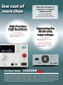
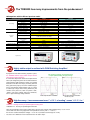
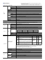
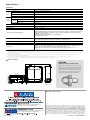
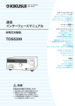
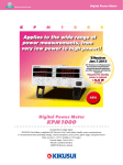
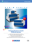
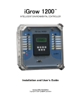
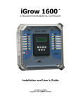
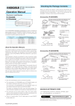
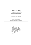
AC Hipot Tester
M O D E L
T O S 5 2 0 0
An ideal AC Hipot Tester
with low cost of ownership
realized, built on more than
50 years of experience in market
NEW
Hipot (Withstanding Voltage) Tester
AC Hipot Tester
TOS5200
Highly-stable output with PWM Amp System
5 kV/100 mA (500 VA) AC Hipot test
Short-circuit current 200 mA or more
Rise time/Fall time control
Equipped with RS232C and USB Interface
An ideal AC Hipot Tester with
ownership realized, built on
50 years of experience !
Rise/Fall Time
control function of
the applied voltage
Equipped with a Rise time/
Fall time control function
Prevents from an excessive stress applied
to the EUT or for standard tests.
Highly stable output
Newly developed, high-efficiency
PWM switching amplifier !
Providing a stable output of high voltage without being
affected by AC line variation. Ensure the user to perform highly
reliable testing with confidence, even in regions with large
voltage variations. (Input voltage fluctuation rate: ±0.3 %)
Variation of
input voltage
Distortion of
input voltage
Input waveform
( phrases in these circles)
Rise Time
Stable High-voltage output !
Fall Time
Pursuing usability
and safety
All new smart design of control panel and
output terminals!
Eliminates the projected components of
output terminals, and equips with a new
type of the LOW terminal. Pursuing the
improvement of safety and a convenience
in production line, such as providing the
protection cover for the front panel.
s Output terminal
Left: HIGH (red)
Right: LOW
(black, with lock function)
s View with the protection cover
removed from front panel
Reducing
the tact time
Increasing the productivity!
Capable of setting the test time from 0.1 s
2
low cost of
more than
High Precision
High Resolution
± 1.5 % of reading*
High-precision measurement ±1.5 % of
reading *(with voltmeter 500 V or higher,
Ammeter 1 mA or higher)
More than 50 years of
experience to support
"JAPAN-quality"
Our electronic safety tester
has more than 50 years of history
since the first product was released in 60's.
Supporting the
World-wide
input voltage
Universal usability !
Usable in any country without changing
the input power supply.
Selectable output frequency !
Not rely on the input power environment.
It supplies the stable test voltage with
50/60 Hz frequencies.
s Rear panel
AC Hipot Tester
TOS5200
NEW
TOS5200 is designed for AC Hipot Test with 500 VA capacity and 200 mA short circuit current output capability.
Equipped with the PWM amplifier, the TOS5200 can provide a stable & reliable output without being affected by AC
power line. Therefore, it is a perfect solution for electronic equipment or devices complied to IEC, EN, UL, VDE and
JIS etc. requirement. As TOS5200 covers most of features of our upper class model for AC Hipot Test, it achieves the
superb cost / performance ratio for those who need 200 VA or 500 VA capacity, or both. Also, as it equips the Interlock
function together with other safety features, operator can carry out the test with higher current value in safe.
3
The TOS5200 has many improvements from the predecessor !
VALUE!
lComparison with the Kikusui previous model
Specification comparison item
Output method
Test voltage
Test time
TOS5050A
Slide transformer method
Distortion
3 % or less
As per commercial power supply waveform
Frequency
50 Hz or 60 Hz
Synchronized with commercial power supply waveform
Output voltage waveform
Sine
Commercial power supply waveform
Voltage regulation
10 % or less
15 % or less
Input voltage variation
±0.3 %
-
Minimum setting value
0.1 s
0.5 s
Accuracy
±(100 ppm + 20 ms) excluding Fall Time
±(100 ppm + 20 ms)
Upper limit setting
AC: 0.01 mA to 110 mA
AC: 0.1 mA to 110 mA
Lower limit setting
AC: 0.01 mA to 110 mA
AC: 0.1 mA to 110 mA
Accuracy
1.00 mA ≤ i: ±(1.5 % of set),
i <1.00 mA: ±(1.5 % of set +30 μA)
Upper limit: ±(5 % + 20 μA)
Rise Time and Fall Time
control features
3
Digital, analog
Judgment
feature
Display
Digital
Measurement accuracy
±1.5 % of reading (V>500V)
±1.5 % f.s
Measurement method
True rms
Average value response/rms value indication
RS-232C Interface
POWER Switch and all function except Key lock
Output for data, test result
Weight
Approx. 14 kg (30.9 lbs)
Approx. 15 kg (33.07 lbs)
100 Vac to 240 Vac
100 V ± 10 %
Voltmeter
Voltmeter/Ammeter
Other
TOS5200
PWM switching amp system
Input power supply
Appearance
VALUE!
Highly stable output is realized with PWM Switching Amplifier!
Equipped with the PWM switching amplifier system,
the TOS5200 realizes highly stable output without
influenced by input form AC line.
A conventional Hipot Tester boosts and outputs the AC
line's input voltage through the use of a slide transformer
system With this slide transformer system, input voltage
fluctuations will affect the output, preventing test from
being performed properly. Since the TOS5200 equips
with a high-efficient PWM amplifier that can output
a stable high-voltage without being affected by the
variation of AC power line, users can perform "safe",
"stable", and highly "reliable" tests with confidence,
even in regions with large voltage variations.
VALUE!
The output waveform is essential factor
in Hipot (Withstanding oltage) testing!
s AC output waveform of TOS5200
s AC output waveform of the slide
transformer system
High-Accuracy = Less measurement error! "+/-1.5 % of reading" versus "+/-1.5 % f.s."
TOS5200 } reading: Accuracy is specified against reading value.
TOS5050A } f.s:Accuracy is specified against full scale.
4
When using TOS5200 at 1500 V output measurement, the max error would be 1500 V(reading value) x 1.5 % = 22.5 V
On the other hand, when using equipment which specifies its accuracy with "+/- 1.5 % f.s.",
the max error could be 2500 V(max voltage) x 1.5 % =37.5 V (it needs to set the range 0 to 2.5 kV)
So, there is 15 V difference of max measurement error at 1500 V output.
Hipot (Withstanding Voltage)Tester
VALUE!
Capable of Test Time setting from 0.1s, which enables to reduce the tact time !
TOS5200 can set the test time from 0.1 sec without sacrificing
measurement accuracy.
This makes test time 5 times faster compared to the TOS5050A (max
test time:0.5sec) and it leads to reduce the tact time.
Reduction of the tact time leads to improve the productivity, so it
has been an issue that reducing the tact time may cause to worsen
the measurement accuracy when the test time is faster than
measurement respond speed.
VALUE!
Cycle time
minimize to
0.32 s
Rise time / Fall time control function
The rise time control function is to prevent the excessive stress that
is being applied to the EUT (test object). The Hipot (Withstanding
voltage) test is conducted to verify the safety performance of the EUT
and which test voltage for Hipot (Withstanding voltage) test is applied
approximately five to ten times greater than the voltage that handles
by the EUT. If a high voltage is applied rapidly with no rise time, the
transitional large voltage (current) will be occurred, and it may cause
a damage to the EUT. For this reason, safety standards stipulate the
procedure of Hipot (Withstanding voltage) test, and the test voltage
must be gradually increased to the specified voltage when the test
is performed. The rise time control function adopted in the in the
TOS5300 Series can set the voltage rise time from 0.1s to 10.0 s (at
a resolution of 0.1 s) and also it is capable to set the 50 % (fixed)
of the applied test voltage. In addition, the fall time control function
enables to decrease the test voltage gradually after the completion of
a PASS judgement. The voltage fall time is fixed at 0.1 s (OFF is also
selectable).
Start
voltage
value
Rise Time control function
The Rise time control
function enables you
t o i n c re a s e s t h e t e s t
voltage gradually to
reach the setting voltage
while the AC Hipot
(Withstanding voltage)
test is conducted. The
voltage rise time can be
set from 0.1 s to 10.0 s
at a resolution of 0.1s.
sRise time control waveform (example)
Fall Time control function
The Fall time control
function enables you to
decrease the test voltage
gradually when the PASS
judgment is made at the
AC Hipot (W ithstanding
voltage) test. The voltage
fall time is fixed at 0.1 s.
(OFF is also selectable).
Output ON
Output OFF
Voltage Rise Time
sStart voltage can be set at 50 % of the test voltage
VALUE!
TOS5200
sFall time control waveform (example)
Improved the setting resolution of the leak current by 0.01 mA !
TOS5200 is can set the current limit from0.01 mA to 110 mA.
(TOS5050A: 0.1 mA to 110 mA)
l Enable to clarify the actual value of device under test (DUT)
l The setting resolution of the lower limit setting has been improved from the previous
model ,it enables to defect the failure more accurately.
sAC Hipot (Withstanding voltage) test settings display (example)
5
n Specifications
Unless specified otherwise, the specifications are for the following settings and conditions.
• The warm-up time is 30 minutes.
• TYP: These are typical values. These values do not guarantee the performance of the product.
• rdng: Indicates the readout value. • set: Indicates a setting. • f.s: Indicates full scale.
n Withstanding voltage tester
Output range
AC
Output
section
0.05 kV to 5.00 kV
Accuracy
± (2 % of set + 20 V) when no load is connected
Operating range
0.00 kV to 5.50 kV
Resolution
10 V steps
Max. rated output *1
500 VA (5 kV/100 mA)
Max. rated voltage
5 kV
Max. rated current
100 mA (when the output voltage is 0.5 kV or greater)
Transformer rating
500 VA
Output voltage waveform *2
Sine
Distortion
Crest factor
If the output voltage is 0.5 kV or more: 3 % or less (when no load or a pure resistive load is connected)
√2 ± 3 % less than (when the output voltage is 800 V or greater, no load)
Frequency
50 Hz or 60 Hz
Accuracy
± 0.5 % (excluding during voltage rise time)
Voltage regulation
10 % or less (when changing from maximum rated load to no load)
Input voltage variation
±0.3 % (5 kV when no load is connected; power supply voltage: 90 V to 250 V)
Short-circuit current
200 mA or more (when the output voltage is 1.0 kV or greater)
Output method
PWM switching
Start voltage
The voltage at the start of withstanding voltage tests can be set to 50 % of the test voltage.
Limit voltage
The test voltage upper limit can be set . AC: 0.00 kV to 5.50 kV
Output voltage monitor feature
If output voltage exceeds the specified value + 350 V or is lower than the specified value - 350 V,
output is turned off, and protective features are activated.
Measurement range
Voltmeter
Digital
0.000 kV to 6.500 kV AC
Display
c . ccc kV
Accuracy
V < 500 V: ± (1.5 % of reading + 20 V), V ≥ 500 V: ±1.5 % of reading
Response *3
True rms, Average value response/rms display switchable
Hold feature
After a test is finished, the measured voltage is retained until the PASS or FAIL judgment is cleared.
Measurement range
0.00 mA to 110 mA
i = measured current
Display
Ammeter
Digital
i < 1 mA
1 mA ≤ i < 10 mA
10 mA ≤ i < 100 mA
100 mA ≤ i
c . ccc mA
c . ccc mA
cc . cc mA
ccc . c mA
Accuracy *4
1.00 mA ≤ i: ± (1.5 % of reading), i < 1.00 mA: ± (1.5 % of reading + 30 μA)
Response *3
True rms, Average value response/rms display switchable
Hold feature
After a test is finished, the measured current value is retained until the PASS judgment is cleared.
Judgment
UPPER
FAIL
Judgment method and
judgment operation
If a current that is less than or equal to the lower limit is
detected, the output is turned off, and a LOWER FAIL
LOWER
judgment occurs. This judgment is not performed during
FAIL
voltage rise time (Rise Time) of all tests and during the
voltage fall time (Fall Time) of AC withstanding voltage tests.
PASS
Judgment feature
Judgment method
Display
If a current that is greater than or equal to the upper limit FAIL LED lights;
is detected, the output is turned off, and an UPPER FAIL UPPER is displayed
on the screen
judgment occurs.
FAIL LED lights;
LOWER is
displayed on the
screen
PASS LED lights;
If the specified time elapses without any problems, the
displayed on the
output is turned off, and a PASS judgment occurs.
screen
Buzzer SIGNAL I/O
ON
Generates
a U-FAIL
signal
ON
Generates
a U-FAIL
signal
ON
Generates
a PASS signal
• If PASS HOLD is enabled, the PASS signal is generated continuously until the TOS5300 Series receives a STOP signal.
• The UPPER FAIL and LOWER FAIL signals are generated continuously until the TOS5300 Series receives a STOP signal.
• The FAIL and PASS buzzer volume levels can be changed.
• For PASS judgments, the length of time that the buzzer sounds for is fixed to 0.2 seconds.
Even if PASS HOLD is enabled, the buzzer turns off after 0.2 seconds.
Upper limit setting
0.01 mA to 110 mA
Lower limit setting
0.01 mA to 110 mA / OFF
Judgment accuracy *4
1.00 mA ≤ i: ± (1.5 % of set), i < 1.00 mA: ± (1.5 % of set + 30 μA)
Current detection method
Calculates the current’s true rms value and compares this value with the reference value
Calibration
Calibrated with the rms of a sine wave using a pure resistive load
Voltage rise time
0.1 s to 10.0 s
Resolution
Time
Voltage fall time
0.1 s / OFF (only enabled when a PASS judgment occurs)
Test Time
0.1 s to 999 s, can be turned off (TIMER OFF)
Resolution
6
Accuracy
0.1 s
0.1 s to 99.9 s: 0.1 s/100 s to 999 s: 1 s
±(100 ppm + 20 ms) excluding Fall Time
Hipot (Withstanding Voltage)Tester
n Specifications
TOS5200
*1. Regarding the output time limits:
Taking size, weight, and cost into consideration, the heat dissipation capability of the voltage generator that is used for withstanding
voltage tests has been designed to be one half that of the rated output. Use the TOS5300 Series within the following limits. If you
use the product in a manner that exceeds these limits, the output section may overheat, and the internal protection circuits may be
activated. If this happens, stop testing, and wait until the TOS5300 Series returns to its normal temperature.
Ambient temperature
t ≤ 40 °C
Pause time
Output time
50 mA < i ≤ 110 mA
Greater than or equal to the output time
30 min. max.
i ≤ 50 mA
Not necessary
Continuous output possible
(Output time = voltage rise time + test time + voltage fall time)
*2. Regarding the test voltage waveform:
Waveform distortions may occur if an DUT whose capacitance is dependent on voltage (for example, an DUT that consists of ceramic
capacitors) is connected as the load. However, if the test voltage is 1.5 kV, the effect of a capacitance of 1000 pF or less can be
ignored.Because the product’s high-voltage power supply uses the PWM switching method, if the test voltage is 500 V or less, the
switching and spike noise proportions are large. The lower the test voltage, the greater the waveform is distorted.
*3. For both True rms and Mean-value response, 50 ms or above response time is required to satisfy the measurement accuracy.
*4. Regarding ammeter and judgment accuracy:
During AC withstanding voltage tests, current also flows in the stray capacitance of items such as the measurement leads and jigs.
This current that flows in the stray capacitances is added to the current that flows in the DUT, and the sum of these currents is
measured.Especially if you want to perform judgments with high sensitivity and accuracy, it is necessary to consider methods to limit
the current that flows in these stray capacitances, such as by adding upper and lower limits.
Output voltage
1 kV
2 kV
5 kV
When using 350 mm long test leads
that are suspended in air (TYP)
2 μA
4 μA
10 μA
When using the accessory,
high test lead TL31-TOS (TYP)
16 μA
32 μA
80 μA
In case of 70 % humidity or higher, it is considerable to add 50 μA on the Limit value.
n Other features / Interfaces
Test mode
Double action feature
Tests can only be started by pressing and releasing STOP and then pressing START within 0.5 seconds of releasing the STOP switch.
Length of time to maintain a PASS judgment result
You can set the length of time to maintain a PASS judgment: 50 ms, 100 ms, 200 ms, 1 s, 2 s,5 s, or HOLD.
Momentary feature
Tests are only executed while the START switch is held down.
Fail mode feature
This feature enables you to prevent remotely transmitted stop signals from clearing FAIL judgments and PROTECTION modes.
Timer feature
This feature finishes tests when the specified time elapses.
Output voltage monitor feature
If output voltage exceeds “setting + 350 V” or is lower than “setting - 350 V,”
the TOS5200 switches to PROTECTION mode, output is turned off, and testing finishes.
Memory
Up to three sets of test conditions can be saved to memory.
Key lock
Locks panel key operations (settings and changes).
Under any of the following conditions, the TOS5200 switches to the PROTECTION state,
immediately turns output off, and stops testing. A message is displayed on the screen.
Protective features
Interlock Protection
An interlock signal has been detected.
Power Supply Protection
An error was detected in the power supply.
Volt Error Protection
While monitoring the output voltage, a voltage outside of the rated limits was detected.
AC or DC withstanding voltage tests: ±350 V
Over Load Protection
During a withstanding voltage test, a value that is greater than or equal to the output limit power was specified.
AC withstanding voltage test: 550 VA.
Over Heat Protection
The internal temperature of the TOS5200 became too high.
Over Rating Protection
During a withstanding voltage test, the output current was generated for a length of time that exceeds the regulated time.
Remote Protection
A connection to or disconnection from the front-panel REMOTE connector was detected.
SIGNAL I/O Protection
The rear-panel SIGNAL I/O connector’s ENABLE signal has changed.
USB Protection
Interfaces
The USB connector has been disconnected while the TOS5200 was being controlled through the USB interface.
USB
USB Specification 2.0
RS-232C *1
D-SUB 9-pin connector on the rear panel (compliant with EIA-232-D)
All functions other than the POWER switch and KEY-LOCK
REMOTE
Front-panel 9-pin MINI DIN connector. By connecting an optional device to this connector,
you can control the starting and stopping of tests remotely.
SIGNAL I/O
Rear-panel D-sub 25-pin connector
*1. "Talk mode" can be set, when RS232-C is used as comunication interface.
Talk mode
Description
0
It responds only for commands from PC. (Default setting)
It responds automatically for start and end test, and returns the status, setting value, measured value.
1
Response at start
Response at
end of test
<START>
Status
<PASS>, <U_FAIL>, <L_FAIL>, <PROT>, <ABOUT>
Setting value, Measured value
Test No., Programme No., Test mode, Measured voltage, Measured current, Test time
7
n Specifications
n General
Display
LCD: LED back custom indicators
Installation location
Indoors, at a height of up to 2000 m
Environ- Spec guaranteed range temperature/humidity
ment
Operating range temperature/humidity
5 °C to 35 °C (41 °F to 95 °F)/20 %rh to 80 %rh (no condensation)
Storage range temperature/humidity
-20 °C to 70 °C (-4 °F to 158 °F)/90 %rh or less (no condensation)
Nominal voltage range (allowable voltage range)
100 VAC to 240 VAC (90 VAC to 250 VAC)
Power
supply
Power
consumptio
0 °C to 40 °C (32 °F to 104 °F)/20 %rh to 80 %rh (no condensation)
When no load is connected (READY)
100 VA or less
When rated load isconnected
800 VA max.
Allowable frequency range
47 Hz to 63 Hz
Insulation resistance (between AC LINE and the chassis)
30 MΩ or more (500 VDC)
Withstanding voltage (between AC LINE and the chassis)
1500 VAC, one minute
Earth continuity
25 AAC, 0.1 Ω or less
Electromagnetic compatibility (EMC) *1
Complies with the requirements of the following directive and standard.
EMC Directive 2004/108/EC, EN 61326-1(ClassA *2), EN 55011(ClassA *2, Group1 *3), EN 61000-3-2, EN 61000-3-3
Applicable under the following conditions The maximum length of all cabling and wiring connected to the
TOS5200 must be less than 2.5 m.
The shielded cable is being used when using the SIGNAL I/O.
The high test lead TL31-TOS
Safety *1
Complies with the requirements of the following directive and standard.
Low Voltage Directive 2006/95/EC, EN 61010-1ed3 (Class I *4 Pollution degree 2)
Dimensions (mm(inches))(maximum)
320 (12.6") (330(12.99")) W × 132(5.2") (150(5.91")) H × 350(13.78") (420(16.54")) D
Weight
Approx. 14 kg (30.9 lbs)
Accessories
Power cord : 1pc. / High test lead (TL31-TOS) : 1set (1 red wire and 1 black wire, each with alligator clips); 1.5 m /
D-sub 25-pin plug : 1set ; assembly type / High-voltage warning sticker : 1pc. /
Setup Guide / Quick Reference(1 each for English and Japanese) / Safety informaion / CD-R *5
*1 Only on models that have the CE marking on the panel. Although signals are insulated with output terminals, each signal is common. Logic setting is also possible.
*2 This is a Class A equipment. This product is intended for use in an industrial environment.
This product may cause interference if used in residential areas. Such use must be avoided unless the user takes special measures to reduce electromagnetic emissions to prevent interference to the reception of
radio and television broadcasts.
*3 This is a Group 1 equipment. This product does not generate and/or use intentionally radio-frequency energy, in the form of electromagnetic radiation, inductive and/or capacitive coupling,
for the treatment of material or inspection/analysis purpose.
*4 This is a Class I equipment. Be sure to ground this product’s protective conductor terminal. The safety of this product is only guaranteed when the product is properly grounded.
*5 Contains the User's Manual, the Cimmunication Interface Manual, VISA library (KI-VISA), IVI-COM driver, and Safety evaluation test.
n Outline drawing
TU01-TOS
Option(s) for Electrical Safety Testers
The TU01-TOS is a terminal unit that converts the 25 pin
SIGNAL I/O connector of the Kikusui TOS5200 Withstanding
Voltage Tester to the 14 pin SIGNAL I/O connector of the
TOS5050A/ 5051A. You can insert this unit between a
controller and a TOS5200 to perform the same external
control that you can perform on the TOS5050A/ 5051A.
294 (11.57”)
350 (13.78”)
265 (10.43”)
MAX20
(0.79”)
38
(1.50”)
132 (5.20”)
MAX150 (5.91”)
MAX330 (12.99”)
320 (12,60”)
MAX420 (16.54”)
250 (9.84”)
Unit: mm (inch)
●Distributor/Representative
1-877-876-2807 www.kikusuiamerica.com
2975 Bowers Avenue, Suite 307, Santa Clara, CA 95051
Phone : 408-980-9433 Facsimile : 408-980-9409
www.kikusui.cn
Room 216,Building 4, No.641,Tianshan Road, Shanghai City, China
Phone : 021-5887-9067 Facsimile : 021-5887-9069
Printed in Japan
■ All products contained in this catalogue are equipment and devices that are premised on use under the supervision
of qualified personnel, and are not designed or produced for home-use or use by general consumers. ■ Specifications,
design and so forth are subject to change without prior notice to improve the quality. ■ Product names and prices are
subject to change and production may be discontinued when necessary. ■ Product names, company names and
brand names contained in this catalogue represent the respective registered trade name or trade mark. ■ Colors,
textures and so forth of photographs shown in this catalogue may differ from actual products due to a limited fidelity
in printing. ■ Although every effort has been made to provide the information as accurate as possible for this catalogue,
certain details have unavoidably been omitted due to limitations in space. ■ If you find any misprints or errors in this
catalogue, it would be appreciated if you would inform us. ■ Please contact our distributors to confirm specifications,
price, accessories or anything that may be unclear when placing an order or concluding a purchasing agreement.
Issue:Oct.2014 2014101KPRIEC11