1
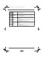
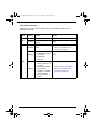
5051 A UM EN CR SP100.fm Page 1 Friday, September 13, 2002 3:26 PM
Centricity™ SP100
User manual
5051 A UM EN CR SP100.fm Page 2 Friday, September 13, 2002 3:26 PM
© GE Medical Systems Information Technologies 2002.
No parts of this document may be reproduced, copied, adapted or transmitted in any form or by any means
without the written permission of GE Medical Systems Information Technologies.
GE Medical Systems Information Technologies makes no warranties or representation, expressed or
implied, with respect to the accuracy, completeness or usefulness of the information contained in this
document and specifically disclaims warranties of suitability for any particular purpose. GE Medical Systems
Information Technologies shall under no circumstances be liable for any damage arising from the use or
inability to use any information, apparatus, method or process disclosed in this document.
GE Medical Systems Information Technologies reserves the right to make changes to this document without
prior notice.
GE Medical Systems Information Technologies, 8200 W. Tower Avenue, Milwaukee, WI 53223, USA.
GE Medical Systems Information Technologies GmbH, Munzinger Strasse 3, D-79111, Freiburg, Germany.
Centricity™ SP100 is a trademark of GE Medical Systems Information Technologies, USA.
GEMS and the GE signature are trademarks of General Electronics Company, USA.
2
5051A EN 20020912
5051 A UM EN CR SP100.fm Page 3 Friday, September 13, 2002 3:26 PM
Table of contents
Chapter 1: Introducing the Centricity™ SP100 ...................................................... 5
Centricity™ SP100 features .................................................................................... 6
Safety precautions .................................................................................................. 7
Safety compliance................................................................................................... 8
Operating modes .................................................................................................... 9
Configurations....................................................................................................... 10
The user interface ................................................................................................. 12
Switching on the Centricity™ SP100..................................................................... 20
Switching off the Centricity™ SP100..................................................................... 22
Chapter 2: Basic operation (‘Operator mode’) ..................................................... 23
Workflow ............................................................................................................... 24
Reading an image plate ........................................................................................ 25
Reading an emergency image plate...................................................................... 31
Re-erasing an image plate .................................................................................... 38
Reading the identification data of a cassette (Dedicated configuration only)......... 42
Changing the image plate type (Dedicated configuration only) ............................. 44
Chapter 3: Advanced operation (‘Key-operator mode’) ...................................... 47
Survey of advanced functions (‘Key-operator mode’) ............................................ 48
Checking the image quality ................................................................................... 49
Troubleshooting checklist...................................................................................... 50
Appendix A: Equipment information sheet .......................................................... 55
5051A EN 20020912
3
5051 A UM EN CR SP100.fm Page 4 Friday, September 13, 2002 3:26 PM
4
5051A EN 20020912
5051 A UM EN CR SP100.fm Page 5 Friday, September 13, 2002 3:26 PM
Chapter
1
Introducing the Centricity™ SP100
This chapter draws attention to important safety precautions and
introduces the Centricity™ SP100.
❑ Centricity™ SP100 features
❑ Safety precautions
❑ Safety compliance
❑ Operating modes
❑ Configurations
❑ The user interface
❑ Switching on the Centricity™ SP100
❑ Switching off the Centricity™ SP100
5051 A UM EN CR SP100.fm Page 6 Friday, September 13, 2002 3:26 PM
Centricity™ SP100 features
The Centricity™ SP100 is a Digitizer for image plates retaining latent X-ray
images. It has been developed for GEMS.
■
The Centricity™ SP100 accepts one cassette containing one image plate at a
time. The Centricity™ SP100:
• takes the cassette containing the image plate from the cassette slot;
• removes the image plate from the cassette;
• scans the image plate;
• converts the information of the latent image to digital data;
• transmits the image data to the preview station;
• erases the image plate and re-inserts it into the cassette;
• gives the cassette ID data the status ‘erased’;
• returns the cassette;
• transmits the digital image data to an image processing station (‘destination’).
■
The Centricity™ SP100 permits assigning the status ‘emergency’ to an image.
An emergency image will be given priority by the image processing station.
■
The Centricity™ SP100 permits re-erasing an image plate before re-using it. In
specific cases, this is necessary to prevent ghost images caused by previous
exposures or stray radiation from interfering with the image of interest.
■
If the Centricity™ SP100 is dedicated to one ID Station, additional features are
available:
• quickly identifying cassettes without the need for an ID Tablet;
• reading the identification data of a cassette;
• initializing a cassette, i.e. changing the image plate type.
■
6
The Pathspeed™ CR Digitizers (Pathspeed™ MP3010, Pathspeed™ SP1001
and Pathspeed™ SP100) and the Centricity™ CR Digitizers (Centricity™
MP3010, Centricity™ SP1001 and Centricity™ SP100) are designed for operation
with Agfa CR cassettes and Agfa CR phosphor plates. Contact your local GE
Medical Systems sales agent for product and ordering information.
5051A EN 20020912
5051 A UM EN CR SP100.fm Page 7 Friday, September 13, 2002 3:26 PM
Safety precautions
General safety instructions
• The Centricity™ SP100 has been designed for scanning medical X-ray image
plates and should only be used for these purposes.
• The Centricity™ SP100 must only be operated by qualified staff.
• Make sure that the Centricity™ SP100 is constantly monitored in order to avoid
inappropriate handling, especially by children.
• Only trained service personnel must make repairs. Only authorized service
personnel must make changes to the Centricity™ SP100.
• If there is any visible damage to the machine casing, do not start nor use the
Centricity™ SP100.
• If you want to connect the Centricity™ SP100 with other devices, components or
assemblies and if the technical data do not permit determining whether the
combination with these devices, components or assemblies involves hazards, you
must consult the respective manufacturers to avoid danger for operating
personnel or the environment.
• Do not override or disconnect the integrated safety features.
• Switch off the Centricity™ SP100 before performing any maintenance work or
repairs. Disconnect the Centricity™ SP100 from the mains before making repairs
or performing any maintenance activities during which live electrical components
may be exposed.
• As is the case for all technical devices, the Centricity™ SP100 must be operated,
cared for and serviced correctly.
• If you don’t operate the Centricity™ SP100 correctly or if you don’t have it
serviced correctly, GE Medical Systems Information Technologies is not liable for
resulting disturbances, damages or injuries.
• When installing the Centricity™ SP100, care must be taken to ensure that there is
either a mains plug or an all-cable disconnecting device in the internal installation
fitted near the Centricity™ SP100 and that it is easily accessible.
5051A EN 20020912
7
5051 A UM EN CR SP100.fm Page 8 Friday, September 13, 2002 3:26 PM
• If you notice conspicuous noise or smoke, disconnect the Centricity™ SP100
immediately.
• Check that the voltage setting of the machine matches the power supply voltage
before connecting the machine to the mains.
Safety instructions for laser products
The Centricity™ SP100 is a Class 1 Laser Product. Under normal operating
conditions - when the service doors are closed - there can be no laser radiation
outside the Centricity™ SP100.
• Open the lower front door only to replace the erasure lamps or the fuses. Open
the right side panel only to solve cassette or image plate jams. When you open the
lower front door or the right side panel, the power supply is switched off
automatically as a precaution.
• Follow meticulously the operation and troubleshooting instructions in the
Centricity™ SP100 User and Reference Manual. Other actions can be hazardous.
Safety compliance
The Centricity™ SP100 complies with:
• the general safety regulations EN 60950, EN 60601-1-2, UL 1950 and
CSA C22.2 No. 950;
• the radio interference regulations EN 55022:1997, Class B and FCC 47, Part 15,
Subchapter B, Class A;
• the laser safety regulations EN 60825-1:1994 and DHHS/FDA 21 CFR,
Parts 1040.10 and 1040.11.
8
5051A EN 20020912
5051 A UM EN CR SP100.fm Page 9 Friday, September 13, 2002 3:26 PM
Operating modes
The Centricity™ SP100 can be operated in three modes: operator mode, keyoperator mode, and service mode.
Operator mode
The operator mode groups all basic functions which are aimed at radiographers:
• Reading an image plate;
• Reading an emergency image plate;
• Re-erasing an image plate;
• Reading the identification data of a cassette (Dedicated configuration only);
• Changing the image plate type (Dedicated configuration only).
All functions of the operator mode are described in Chapter 2, ‘Basic operation
(‘Operator mode’)’.
Key-operator mode
The key-operator mode groups advanced functions which are aimed at
technicians.
The key-operator mode can be accessed via the Key-operator key on the
keypad and is menu-driven. The key-operator functions are described in
Chapter 3, ‘Advanced operation (‘Key-operator mode’)’ of the Centricity™
SP100 Reference manual.
Service mode
The service mode functions are reserved for trained service personnel. They are
password protected.
5051A EN 20020912
9
5051 A UM EN CR SP100.fm Page 10 Friday, September 13, 2002 3:26 PM
Configurations
The Centricity™ SP100 can be used in two configurations: either one or more ID
Stations serve a range of Digitizers, or one ID Station is dedicated to one
Digitizer. The ID Software installed on the ID Station is slightly different
depending on the configuration. For more information, contact your local service
organization.
Interchangeable configuration
One or more ID Stations can serve a range of Digitizers, provided that each ID
Station has an ID Tablet. There is no physical link required between the ID
Station and the Digitizer.
In this configuration, a cassette can be identified via any of the ID Stations and
subsequently be scanned using any of the Digitizers. The patient demographic
data and examination data are entered via the ID Station and stored in the
memory chip of the Centricity™ CR compatible cassette via the ID Tablet. As a
result the identification data are linked to the cassette and any Digitizer can be
used to scan the cassette.
The interchangeable configuration permits the flexible use of several Digitizers
and ID Stations depending on the workload.
Centricity™
SP100
ID Station with
ID Tablet
Interchangeable configuration
10
5051A EN 20020912
5051 A UM EN CR SP100.fm Page 11 Friday, September 13, 2002 3:26 PM
Dedicated configuration
If one ID Station is dedicated to one Digitizer, cassettes can be identified without
using an ID Tablet. The identification data are transmitted from the ID Station to
the Digitizer via the network.
The dedicated configuration reduces the time required for identifying and
scanning a cassette because both actions can be performed simultaneously.
Centricity™ SP100
ID Station without ID Tablet
Dedicated configuration
❖
In the dedicated configuration, you can still use the Centricity™ SP100 to
digitize cassettes which have been identified on other ID Stations.
5051A EN 20020912
11
5051 A UM EN CR SP100.fm Page 12 Friday, September 13, 2002 3:26 PM
The user interface
The Centricity™ SP100 has three operation modes:
• the operator mode for basic operation;
• the key-operator mode for advanced operation;
• the service mode reserved for trained service personnel.
The functions of the operator mode are described in Chapter 2, ‘Basic operation
(‘Operator mode’)’. An overview of the functions of the key-operator mode is
given in ‘Survey of advanced functions (‘Key-operator mode’)’ on page 48. For
detailed information on the key-operator mode, refer to the Centricity™ SP100
Reference manual.
The Centricity™ SP100 interfaces with the user via:
• a keypad and a display;
• a status indicator;
• emergency buttons;
• audio signals.
1 2
12
3
1
Status indicator
2
Emergency buttons
3
Keypad and display
5051A EN 20020912
5051 A UM EN CR SP100.fm Page 13 Friday, September 13, 2002 3:26 PM
The keypad
The Centricity™ SP100 keypad features the following keys:
5051A EN 20020912
Emergency
key
To give an image the status ‘emergency’ when it is
sent to the image processing station.
This key can only be used for cassettes with ID data.
Erase key
To erase images without digitizing them.
This must be done if:
• an image plate has not been used for more than
3 days;
• an image plate has been exposed to an
exceptionally high X-ray dose.
Keyoperator
key
To access advanced functions (‘key-operator
functions’).
Service key
To access service-level functions.
Reserved for trained service personnel.
Escape key
To quit the current function or exit a menu without
saving modifications.
Confirm key
In key-operator mode:
• to select a menu.
• to accept an entry in a menu and go back to
operator mode.
13
5051 A UM EN CR SP100.fm Page 14 Friday, September 13, 2002 3:26 PM
14
Up key
• To move the cursor to the previous entry field.
• To scroll upwards.
• To increment the number in a numeric entry field.
Down key
• To move the cursor to the next entry field.
• To scroll downwards.
• To decrement the number in a numeric entry field.
Left key
• To scroll backwards through multiple choices within
a field.
• To move the entry position in a numerical entry field
from right to left.
• To toggle between values in a field.
Right key
• To scroll forwards through multiple choices within a
field.
• To move the entry position in a numerical entry field
from left to right.
• To toggle between values in a field.
5051A EN 20020912
5051 A UM EN CR SP100.fm Page 15 Friday, September 13, 2002 3:26 PM
The display
The Centricity™ SP100 control panel has a backlit LCD display with 8 lines of 40
characters each. Its lay-out depends on the operating mode.
◆ In operator mode, the display has dedicated areas for specific information:
2
1
Set-up
8.1
8.2
8.3
3
4
STATUS
OPERATION MODE
1ST MESSAGE
2nd Message
Patient_Last_Name
Sub_Exam
Patient_Last_Name
Sub_Exam
Patient_Last_Name
Sub_Exam
Station Name
ERROR
5
6
7
1
Set-up of image processing station:
•
•
•
•
[blank]: Default image processing station selected.
Off line: Transmission to all image processing stations disabled.
[process.station] not ready: Image processing station not available.
[process.station] rerouted: Images rerouted to other image processing
station.
2
Type of message
3
Extra comment or action to take
4
System status:
• READY: The Centricity™ SP100 is ready for operation.
• BUSY: The Centricity™ SP100 is treating an image plate.
• ERROR: An error has occurred. Refer to ‘Troubleshooting checklist’ on
page 50.
• LOCKED: id.
• WARNING: id.
5051A EN 20020912
15
5051 A UM EN CR SP100.fm Page 16 Friday, September 13, 2002 3:26 PM
5
Operation mode:
• [blank]: Normal operation mode.
• EMERGENCY: Emergency function for image plates with ID data.
• EMERGENCY BUTTON: Emergency function for image plates without
ID data.
• ERASURE: Re-erasure function.
• DIRECT ID: Operation in dedicated configuration.
6
Error status: service code (SERVICE XXXXX) or error code (CODE XXXXX)
7
Station name of the Centricity™ SP100
Identifier of image plate being treated:
8.1
After image ID data is read;
8.2
During scanning of image plate and transmittal of image data;
8.3
During transmittal of image data to image processing station.
The operator main screen is:
READY
SP100
16
5051A EN 20020912
5051 A UM EN CR SP100.fm Page 17 Friday, September 13, 2002 3:26 PM
When the Centricity™ SP100 is treating an image plate, it displays the following
screen:
BUSY
Miller
Chest AP
◆ In key-operator mode, operation is menu driven. The menu displays the keyoperator functions, the active keys, and the service code.
1
Queue management
Digitizer set-up
Date and Time
Send test image
System info
Install
Save configuration
Fast preview
KEY-OPERATOR
MENU
: quit
: ok
: select
SERVICE XXXXX
1
Key-operator functions
2
Active keys
3
Service code
2
3
◆ In operator mode and in key-operator mode, both informational and warning
messages can be displayed. Informational messages are displayed as black text
against a white background; warning messages are displayed in reverse mode.
5051A EN 20020912
17
5051 A UM EN CR SP100.fm Page 18 Friday, September 13, 2002 3:26 PM
The status indicator
The light at the top of the Centricity™ SP100 indicates the status of the
Centricity™ SP100.
Color
Green
Constant/
Flashing
Status
Action
Constant
Ready.
Proceed.
Flashing
Busy (treating image
plate).
Wait.
Constant
Error.
• Check display for messages.
• Refer to ‘Troubleshooting
checklist’ on page 50.
Flashing
• Reading
identification data of
a cassette.
• Initializing a
cassette.
Wait.
Flashing
• Locked or warning.
• Power on/self-test in
progress.
• Key-operator mode.
• Service mode.
• Centricity™ SP100
not connected to
image processing
station.
• Check display for messages.
• Refer to ‘Troubleshooting
checklist’ on page 50.
Red
18
5051A EN 20020912
5051 A UM EN CR SP100.fm Page 19 Friday, September 13, 2002 3:26 PM
Emergency buttons
Two emergency buttons are located at the front of the Centricity™ SP100. The
emergency buttons determine the speed class, i.e. the sensitivity, which will be
used to digitize the image plate. The sensitivity associated with the emergency
buttons has been set during the configuration of your system. For more
information, contact your local service organization.
The emergency buttons have the following labels:
For digitizing images of the trunk.
For digitizing images of the limbs.
■
In the interchangeable configuration, the emergency buttons permit you to
digitize emergency image plates without ID data.
■
In the dedicated configuration, the emergency buttons permit you to digitize
an image plate while you are entering the identification data via the ID Station.
Audio signals
The Centricity™ SP100 gives status information via beeps. The length of the
beep indicates the response of the system to a key command.
• A short beep means that Centricity™ SP100 has accepted the key command and
is starting the operation.
• A long beep means that you have pressed a non-active key or that the
Centricity™ SP100 has rejected the key command.
• An interval beep accompanies an error, locked or warning message. Refer to
‘Troubleshooting checklist’ on page 50.
5051A EN 20020912
19
5051 A UM EN CR SP100.fm Page 20 Friday, September 13, 2002 3:26 PM
Switching on the Centricity™ SP100
1
Make sure that the setting of the voltage selector at the back of the machine
matches the power supply voltage.
120
230-240
100
2
20
Locate the main switch and place it in position ‘I’.
5051A EN 20020912
5051 A UM EN CR SP100.fm Page 21 Friday, September 13, 2002 3:26 PM
The machine starts a self-test which may take up to 3 minutes. The following screen
is displayed:
WAIT
Self test proceeding
❖
During the self-test, you cannot activate any functions.
If the Centricity™ SP100 has completed the self-test successfully, the Centricity™
SP100 enters the operator mode and displays the operator main screen:
READY
SP100
❖
If the Centricity™ SP100 displays:
ERROR
Self test failed
SERVICE XXXXX
contact your local service organization.
5051A EN 20020912
21
5051 A UM EN CR SP100.fm Page 22 Friday, September 13, 2002 3:26 PM
Switching off the Centricity™ SP100
Before switching off
Check that the Centricity™ SP100 is not scanning an image plate. If the
Centricity™ SP100 is scanning an image plate, the status indicator at the top of
the machine is green and flashing.
Switching off
It is recommended to switch off the Centricity™ SP100 at the end of the day.
Only switch off the Centricity™ SP100 if you do not intend to digitize
emergency image plates overnight. Switching on the Centricity™ SP100
takes approximately 3 minutes. During this time emergency digitizing is not
possible!
Place the main switch in position ‘0’.
22
5051A EN 20020912
5051 A UM EN CR SP100.fm Page 23 Friday, September 13, 2002 3:26 PM
Chapter
Basic operation
(‘Operator mode’)
This chapter provides basic information on how to digitize
image plates under normal conditions and in emergency
situations. It also treats how to re-erase an image plate to
prevent ghost images caused by previous exposures or by
stray radiation. These functions are available in operator
mode.
❑ Workflow
❑ Reading an image plate
❑ Reading an emergency image plate
❑ Re-erasing an image plate
❑ Reading the identification data of a cassette (Dedicated
configuration only)
❑ Changing the image plate type (Dedicated configuration
only)
2
5051 A UM EN CR SP100.fm Page 24 Friday, September 13, 2002 3:26 PM
Workflow
The workflow for identifying cassettes and digitizing image plates depends on
the configuration of your system.
■
In the interchangeable configuration a cassette is uniquely identified by the
identification data in the cassette chip. Therefore, you must first identify the
cassette via the ID Station with ID Tablet before you can digitize the image plate.
Refer to ‘Reading an image plate in the interchangeable configuration’ on
page 25.
❖
■
24
An exception are emergency image plates which you can digitize without
having identified the cassette. The unidentified emergency image plate will
be given default ID data. Refer to ‘Reading an emergency image plate in the
interchangeable configuration’ on page 31.
In the dedicated configuration the identification data are transmitted from the
ID Station to the dedicated Centricity™ SP100 via the network. Therefore, the
Centricity™ SP100 can digitize the image plate while you are entering the
identification data on the ID Station. Refer to ‘Reading an image plate in the
dedicated configuration’ on page 28.
5051A EN 20020912
5051 A UM EN CR SP100.fm Page 25 Friday, September 13, 2002 3:26 PM
Reading an image plate
The main function of the Centricity™ SP100 is digitizing image plates and
transmitting the digital image data to the preview station and the image
processing station. The actual workflow depends on the configuration of your
system.
Reading an image plate in the interchangeable configuration
In the interchangeable configuration, you must first identify the cassette via an
ID Station with ID Tablet before you can digitize the image plate.
To read an image plate:
1
Make sure the cassette has been identified properly via the ID Station.
2
Check that the Centricity™ SP100 is ready for operation:
• the Centricity™ SP100 must display the operator main screen with ‘Ready’ status,
e.g.:
QS not ready
READY
Status field
SP100
• the status indicator at the top of the Centricity™ SP100 must be green and be lit
constantly.
❖
The Centricity™ SP100 is operational if the status field equals ‘READY’,
even if status messages of the destination are shown (e.g. ‘QS not ready’).
5051A EN 20020912
25
5051 A UM EN CR SP100.fm Page 26 Friday, September 13, 2002 3:26 PM
3
Insert the cassette containing the image plate into the cassette slot of the
Centricity™ SP100 as shown below.
Make sure to insert the cassette with the hinge [1] at the top and the locking
mechanism [2] at the bottom.
1
2
While treating the image plate, the Centricity™ SP100 will display the following
screen:
BUSY
Miller
Chest AP
SP100
The Centricity™ SP100:
• reads the cassette identification data;
• converts the information of the latent image to digital data;
• if fast preview is enabled, transmits the digital image data in blocks of typical 100
lines to the preview station;
• erases the image plate and re-inserts it into the cassette;
• gives the cassette ID data the status ‘erased’;
• returns the cassette;
• transmits the digital image data to the image processing station (‘destination’).
26
5051A EN 20020912
5051 A UM EN CR SP100.fm Page 27 Friday, September 13, 2002 3:26 PM
When the Centricity™ SP100 has treated the cassette, it displays the operator main
screen.
❖
4
If the Centricity™ SP100 displays an error message, refer to ‘Troubleshooting
checklist’ on page 50.
Remove the cassette from the cassette slot.
When the Centricity™ SP100 returns the cassette, it is ready to be re-used
immediately. However, if you leave it for more than 3 days before re-using it,
you must re-erase it first. Refer to ‘Re-erasing an image plate’ on page 38.
5051A EN 20020912
27
5051 A UM EN CR SP100.fm Page 28 Friday, September 13, 2002 3:26 PM
Reading an image plate in the dedicated configuration
In the dedicated configuration, the Centricity™ SP100 can digitize the image
plate while you are entering the identification data via the ID Station.
To read an image plate:
1
Check that the Centricity™ SP100 is ready for operation:
• the Centricity™ SP100 must display the operator main screen with ‘Ready’ status,
e.g.:
QS not ready
READY
Status field
SP100
• the status indicator at the top of the Centricity™ SP100 must be green and be lit
constantly.
❖
2
The Centricity™ SP100 is operational if the status field equals ‘READY’,
even if status messages of the destination are shown (e.g. ‘QS not ready’).
Press the appropriate emergency button at the front of the Centricity™ SP100.
The emergency button determines the speed class, i.e. the sensitivity, which will be
used to digitize the image plate.
For digitizing images of the trunk.
For digitizing images of the limbs.
The button which you have pressed will be lit and the display will read:
BUSY
DIRECT ID
IDENTIFY AT ID STATION
or press
to use emergency data
SP100
28
5051A EN 20020912
5051 A UM EN CR SP100.fm Page 29 Friday, September 13, 2002 3:26 PM
3
Insert the cassette containing the image plate into the cassette slot of the
Centricity™ SP100 as shown below.
Make sure to insert the cassette with the hinge [1] at the top and the locking
mechanism [2] at the bottom.
1
2
The Centricity™ SP100 starts digitizing the image plate. You can enter the
identification data, refer to step 4.
While treating the image plate, the Centricity™ SP100 will display the following
screen:
BUSY
DIRECT ID
IDENTIFY AT ID STATION
or press
to use emergency data
SP100
The Centricity™ SP100 converts the information of the latent image to digital data.
❖
If the Centricity™ SP100 displays an error message, refer to Chapter 3,
‘Advanced operation (‘Key-operator mode’)’.
5051A EN 20020912
29
5051 A UM EN CR SP100.fm Page 30 Friday, September 13, 2002 3:26 PM
4
Enter the identification data via the ID Station.
For detailed information, refer to the User manual of the Centricity™ CR ID Software.
As soon as you have entered the identification data, the Centricity™ SP100 displays:
BUSY
Miller
Chest AP
SP100
If fast preview is enabled, the image data are sent to the preview station as soon as
you have entered the identification data. The image data are sent in blocks of typical
100 lines. For more information, refer to the User manual of the Centricity™ CR
Preview Software.
As soon as the Centricity™ SP100 has digitized the entire image plate and you have
entered the identification data:
• the Centricity™ SP100 erases the image plate and re-inserts it into the cassette;
• the Centricity™ SP100 gives the cassette ID data the status ‘erased’.
• the cassette is returned to the cassette slot;
• the digital image data is sent to the image processing station (‘destination’).
When the Centricity™ SP100 has treated the cassette, it displays the operator main
screen.
5
Remove the cassette from the cassette slot.
When the Centricity™ SP100 returns the cassette, it is ready to be re-used
immediately. However, if you leave it for more than 3 days before re-using it,
you must re-erase it first. Refer to ‘Re-erasing an image plate’ on page 38.
30
5051A EN 20020912
5051 A UM EN CR SP100.fm Page 31 Friday, September 13, 2002 3:26 PM
Reading an emergency image plate
You may have an image plate which you wish to give priority over other image
plates which are being processed by the image processing station. Such image
plates are referred to as 'emergency image plates'. The actual workflow
depends on the configuration of your system.
Reading an emergency image plate in the interchangeable
configuration
In the interchangeable configuration, you can treat either:
◆ emergency image plates with ID data via the Emergency key on the keypad;
◆ emergency image plates without ID data via the emergency buttons at the
front of the Centricity™ SP100.
Reading emergency image plates with ID data
To read an emergency image plate with ID data:
1
Make sure the cassette has been identified properly via the ID Station.
2
Check that the Centricity™ SP100 is ready for operation:
• the Centricity™ SP100 must display the operator main screen with ‘Ready’ status,
e.g.:
QS not ready
READY
Status field
SP100
• the status indicator at the top of the Centricity™ SP100 must be green and be lit
constantly.
❖
The Centricity™ SP100 is operational if the status field equals ‘READY’,
even if status messages of the destination are shown (e.g. ‘QS not ready’).
5051A EN 20020912
31
5051 A UM EN CR SP100.fm Page 32 Friday, September 13, 2002 3:26 PM
3
Press the Emergency key on the keypad.
The display will read:
READY
EMERGENCY
WARNING
Next cassette gets emergency status
SP100
The emergency status will only be assigned to the first image plate which
you insert into the Centricity™ SP100 cassette slot after pressing the
Emergency key.
4
Insert the cassette containing the emergency image plate into the cassette slot
as shown below. Make sure to insert the cassette with the hinge [1] at the top
and the locking mechanism [2] at the bottom.
1
2
When the Centricity™ SP100 has treated the emergency image plate, it displays the
operator main screen. The image processing station will give the emergency image
priority over the other images in the image processing queue.
❖
5
32
If you do not enter a cassette within 1 minute after pressing the Emergency
key or if you enter a cassette without ID data, the Centricity™ SP100 will quit
the emergency function and return to the operator main screen.
Remove the cassette from the cassette slot.
5051A EN 20020912
5051 A UM EN CR SP100.fm Page 33 Friday, September 13, 2002 3:26 PM
Reading emergency image plates without ID data
To read an emergency image plate without ID data:
1
Check that the Centricity™ SP100 is ready for operation:
• the Centricity™ SP100 must display the operator main screen with ‘Ready’ status,
e.g.:
READY
Status field
SP100
• the status indicator at the top of the Centricity™ SP100 must be green and be lit
constantly.
❖
2
The Centricity™ SP100 is operational if the status field equals ‘READY’,
even if status messages of the destination are shown (e.g. ‘QS not ready’).
Press the appropriate emergency button at the front of the Centricity™ SP100.
The emergency button determines the speed class, i.e. the sensitivity, which will be
used to digitize the image plate.
For digitizing unidentified emergency images of the trunk.
For digitizing unidentified emergency images of the limbs.
The button which you have pressed will be lit and the display will read:
READY
EMERG. BUTTON
WARNING
Please enter unidentified cassette
SP100
The emergency status will only be assigned to the first image plate which
you insert in the Centricity™ SP100 cassette slot after pressing the
emergency button.
5051A EN 20020912
33
5051 A UM EN CR SP100.fm Page 34 Friday, September 13, 2002 3:26 PM
3
Insert the cassette containing the emergency image plate into the cassette slot
as shown below.
Make sure to insert the cassette with the hinge [1] at the top and the locking
mechanism [2] at the bottom.
1
2
The image plate will be digitized using the speed class, i.e. the sensitivity,
corresponding to the emergency button as defined during configuration.
When the Centricity™ SP100 has treated the emergency image plate, it displays the
operator main screen. The digital image data are transmitted to the image
processing station accompanied by default ID data. The image processing station will
give the emergency image priority over the other images in the image processing
queue.
4
34
❖
If you do not enter a cassette within 15 seconds after pressing the
emergency button, the Centricity™ SP100 will quit the emergency button
function and return to the operator main screen.
❖
To change the speed class corresponding to the emergency button, contact
your local service organization.
Remove the cassette from the cassette slot.
5051A EN 20020912
5051 A UM EN CR SP100.fm Page 35 Friday, September 13, 2002 3:26 PM
Reading an emergency image plate in the dedicated configuration
In the dedicated configuration, you can digitize unidentified emergency image
plates. The digital image data will be assigned default ID data.
To digitize an emergency image plate, you must press the Confirm key after
you have inserted the cassette (refer to step 4). Image data transmission to
the preview and the image processing station will be suspended until you
have pressed the Confirm key.
To read an emergency image plate:
1
Check that the Centricity™ SP100 is ready for operation:
• the Centricity™ SP100 must display the operator main screen with ‘Ready’ status,
e.g.:
QS not ready
READY
Status field
SP100
• the status indicator at the top of the Centricity™ SP100 must be green and be lit
constantly.
❖
2
The Centricity™ SP100 is operational if the status field equals ‘READY’,
even if status messages of the destination are shown (e.g. ‘QS not ready’).
Press the appropriate emergency button at the front of the Centricity™ SP100.
The emergency button determines the speed class, i.e. the sensitivity, which will be
used to digitize the image plate.
For digitizing images of the trunk.
For digitizing images of the limbs.
5051A EN 20020912
35
5051 A UM EN CR SP100.fm Page 36 Friday, September 13, 2002 3:26 PM
The button which you have pressed will be lit and the display will read:
BUSY
DIRECT ID
IDENTIFY AT ID STATION
or press
to use emergency data
SP100
3
Insert the cassette containing the image plate into the cassette slot of the
Centricity™ SP100 as shown below.
Make sure to insert the cassette with the hinge [1] at the top and the locking
mechanism [2] at the bottom.
1
2
The Centricity™ SP100 starts digitizing the image plate.
While treating the image plate, the Centricity™ SP100 will display the following
screen:
BUSY
DIRECT ID
IDENTIFY AT ID STATION
or press
to use emergency data
SP100
36
5051A EN 20020912
5051 A UM EN CR SP100.fm Page 37 Friday, September 13, 2002 3:26 PM
4
Press the Confirm key.
The Centricity™ SP100 displays:
BUSY
SP100 EMERGENCY
[Examination type]
SP100
• If you pressed the emergency button for digitizing images of the limbs,
[Examination type] equals ‘Extremities‘.
• If you pressed the emergency button for digitizing images of the trunk,
[Examination type] equals ‘Corpus’.
When the Centricity™ SP100 has treated the emergency image plate, it displays the
operator main screen. The digital image data are transmitted to the image
processing station accompanied by default ID data. The image processing station will
give the emergency image priority over the other images in the image processing
queue.
5
Remove the cassette from the cassette slot.
5051A EN 20020912
37
5051 A UM EN CR SP100.fm Page 38 Friday, September 13, 2002 3:26 PM
Re-erasing an image plate
At the end of a normal or emergency digitizing cycle, the Centricity™ SP100
returns an erased image plate. However, in the following cases, you must reerase the image plate before re-using it in order to prevent ghost images from
interfering with the image of interest:
• If the image plate has not been used for more than 3 days.
In this case, the image plate may have been exposed to stray radiation.
• If an image plate has been exposed to an exceptionally high X-ray dose.
In this case, deep layers of the image plate may still retain a latent image after
standard erasure. Leave the image plate to rest at least one day before re-erasing
it.
You can erase image plates which you have given the status ‘to be erased’ via
the ID Station or image plates which have the status ‘erased’.
Re-erasing image plates with status ‘erased’
To re-erase an image plate which has been erased as part of a normal or
emergency digitizing cycle:
1
Check that the Centricity™ SP100 is ready for operation:
• the Centricity™ SP100 must display the operator main screen with ‘Ready’ status,
e.g.:
READY
Status
SP100
• the status indicator at the top of the Centricity™ SP100 must be green and be lit
constantly.
2
38
Press the Erase key on the keypad.
5051A EN 20020912
5051 A UM EN CR SP100.fm Page 39 Friday, September 13, 2002 3:26 PM
The display will read:
READY
ERASURE
WARNING
The next cassette will be erased
Put cassette in slot or press
3
to quit
Insert the cassette into the cassette slot.
While erasing, the Centricity™ SP100 will still display the above screen. When the
Centricity™ SP100 has erased the image plate, it displays the operator main screen.
Warning
If the above screen is not displayed but the display reads:
LOCKED
ERASURE
ERASE “PATIENT NAME”?
Press
to erase or
to scan
You have entered a cassette with ID data not having the status ‘erased’. You
now have the choice: either cancel erasing or erase the image plate.
◆ To cancel erasing and make a regular scan: press the Escape key.
5051A EN 20020912
39
5051 A UM EN CR SP100.fm Page 40 Friday, September 13, 2002 3:26 PM
◆ To erase the image plate: press the Confirm key.
While erasing, the Centricity™ SP100 will display:
READY
ERASURE
WARNING
The next cassette will be erased
Put cassette in slot or press
to quit
When the Centricity™ SP100 has erased the image plate, it displays the operator
main screen.
4
40
Remove the cassette from the cassette slot.
5051A EN 20020912
5051 A UM EN CR SP100.fm Page 41 Friday, September 13, 2002 3:26 PM
Re-erasing image plates with status ‘to be erased’
To re-erase an image plate which you have given the status ‘to be erased’ via
the ID station:
1
Check that the Centricity™ SP100 is ready for operation:
• the Centricity™ SP100 must display the operator main screen with ‘Ready’ status,
e.g.:
READY
Status
SP100
• the status indicator at the top of the Centricity™ SP100 must be green and be lit
constantly.
2
Insert the cassette into the cassette slot.
The Centricity™ SP100 will automatically erase the image plate. The display will
read:
BUSY
* * * ERASING * * *
When the Centricity™ SP100 has erased the image plate, it displays the operator
main screen.
3
Remove the cassette from the cassette slot.
5051A EN 20020912
41
5051 A UM EN CR SP100.fm Page 42 Friday, September 13, 2002 3:26 PM
Reading the identification data of a cassette
(Dedicated configuration only)
In the dedicated configuration, the identification data stored in the memory chip
of the cassette can be read via the Centricity™ SP100.
To read the identification data of a cassette:
1
Check that the Centricity™ SP100 is ready for operation:
• the Centricity™ SP100 must display the operator main screen with ‘Ready’ status,
e.g.:
QS not ready
READY
Status field
SP100
• the status indicator at the top of the Centricity™ SP100 must be green and be lit
constantly.
❖
2
The Centricity™ SP100 is operational if the status field equals ‘READY’,
even if status messages of the destination are shown (e.g. ‘QS not ready’).
In the ID Software on the ID Station, select the mode for reading cassettes.
Refer to the User manual of the ID Software.
The display of the Centricity™ SP100 will read:
BUSY
DIRECT ID
READ CASSETTE MODE
Enter cassette or press
to cancel
SP100
42
5051A EN 20020912
5051 A UM EN CR SP100.fm Page 43 Friday, September 13, 2002 3:26 PM
3
Insert the cassette containing the image plate into the cassette slot of the
Centricity™ SP100 as shown below.
Make sure to insert the cassette with the hinge [1] at the top and the locking
mechanism [2] at the bottom.
1
2
While the Centricity™ SP100 reads the identification data from the cassette chip, the
status indicator at the top of the machine is red and flashing.
The identification data will be displayed on the ID Station. Subsequently, the
Centricity™ SP100 returns the cassette to the cassette slot and displays the operator
main screen.
4
Remove the cassette from the cassette slot.
5051A EN 20020912
43
5051 A UM EN CR SP100.fm Page 44 Friday, September 13, 2002 3:26 PM
Changing the image plate type (Dedicated
configuration only)
If you use new generation Centricity™ CR compatible phosphor plates, the
cassettes containing the plates must first be initialized. The new generation of
plates can be identified by the plate type and the initializing code printed on the
back (e.g. MD 30 19).
If you purchased cassettes already containing Centricity™ CR compatible
phosphor plates, the cassettes are ready for use. If you purchased
Centricity™ CR compatible phosphor plates or cassettes separately, the
cassettes must be initialized first.
In the dedicated configuration, you can initialize cassettes via the Centricity™
SP100.
To initialize a cassette:
1
Check that the Centricity™ SP100 is ready for operation:
• the Centricity™ SP100 must display the operator main screen with ‘Ready’ status,
e.g.:
QS not ready
READY
Status field
SP100
• the status indicator at the top of the Centricity™ SP100 must be green and be lit
constantly.
❖
44
The Centricity™ SP100 is operational if the status field equals ‘READY’,
even if status messages of the destination are shown (e.g. ‘QS not ready’).
5051A EN 20020912
5051 A UM EN CR SP100.fm Page 45 Friday, September 13, 2002 3:26 PM
2
In the ID Software on the ID Station, select the mode for initializing cassettes.
Refer to the User manual of the ID Software.
The display of the Centricity™ SP100 will read:
BUSY
DIRECT ID
SET PLATE TYPE MODE
Enter cassette or press
to cancel
SP100
3
Insert the cassette containing the image plate into the cassette slot of the
Centricity™ SP100 as shown below.
Make sure to insert the cassette with the hinge [1] at the top and the locking
mechanism [2] at the bottom.
1
2
4
Enter the initialization code in the ID Software.
Refer to the User manual of the ID Software.
While the Centricity™ SP100 the initializes the cassette, the status indicator at the
top of the machine is red and flashing.
When the cassette has been initialized, the Centricity™ SP100 returns the cassette
to the cassette slot and displays the operator main screen.
5
Remove the cassette from the cassette slot.
5051A EN 20020912
45
5051 A UM EN CR SP100.fm Page 46 Friday, September 13, 2002 3:26 PM
46
5051A EN 20020912
5051 A UM EN CR SP100.fm Page 47 Friday, September 13, 2002 3:26 PM
Chapter
3
Advanced operation
(‘Key-operator mode’)
This chapter gives an overview of the key-operator functions,
preventive maintenance actions and troubleshooting. For detailed
information on these topics, refer to the Reference manual.
❑ Survey of advanced functions (‘Key-operator mode’)
❑ Checking the image quality
❑ Troubleshooting checklist
5051 A UM EN CR SP100.fm Page 48 Friday, September 13, 2002 3:26 PM
Survey of advanced functions
(‘Key-operator mode’)
A survey of the functions which are available in key-operator mode is given
below. For detailed information, refer to Chapter 3, ‘Advanced operation (‘Keyoperator mode’)’ of the Centricity™ SP100 Reference manual.
Function in
key-operator main menu
48
Section in Reference Manual
Page
Queue management
‘Consulting the image transmission
queue (‘Queue management’)’.
48
Digitizer set-up
‘Customizing the Centricity™ SP100
(‘Digitizer set-up’)’.
52
Date and Time
‘Setting the date and time’.
57
Send test image
‘Sending test images’.
58
System info
‘Consulting information on the
Centricity™ SP100’.
59
Install
‘Installing a new software version’.
59
‘Installing a new language’.
69
‘Installing new customer parameters’.
75
Save configuration
‘Saving the configuration data on a
diskette (backup)’.
81
Fast preview
‘Enabling/disabling fast preview’
85
‘Setting the fast preview station for
emergency image plates’
87
5051A EN 20020912
5051 A UM EN CR SP100.fm Page 49 Friday, September 13, 2002 3:26 PM
Checking the image quality
The only maintenance action which you must perform is checking the image
quality. Refer to the Reference manual of the image processing system.
5051A EN 20020912
49
5051 A UM EN CR SP100.fm Page 50 Friday, September 13, 2002 3:26 PM
Troubleshooting checklist
A survey of possible problems is listed below. If corrective actions are
straightforward, they are given below. The more elaborate troubleshooting
procedures are explained in detail in Chapter 4, ‘Preventive maintenance and
troubleshooting’ of the Centricity™ SP100 Reference manual
General errors
Error
Action
The Centricity™ SP100 does not
Refer to ‘Checking the voltage supply’ on
page 101 of the Reference manual.
start up.
Errors during operation
Set-up display
STATUS
FUNCTION MODE
1ST MESSAGE ARRAY
2nd Message Array
Patient_Last_Name
Sub_Exam
Patient_Last_Name
Sub_Exam
Patient_Last_Name
Sub_Exam
Station Name
ERROR
Status field:
Error field:
ERROR
‘SERVICE XXXXX’
Contact your local service organization.
Status field:
Error field:
ERROR
‘CODE XXXXX’
MESSAGE 1
Message 2
POWER SUPPLY OUT
OF TOLERANCE
1. Check setting of
voltage selector
switch on back
panel.
2. Check fuses of
the machine
Action
Refer to ‘Checking the voltage
supply’ on page 101 of the
Reference manual.
3. Check supply
voltage.
50
5051A EN 20020912
5051 A UM EN CR SP100.fm Page 51 Friday, September 13, 2002 3:26 PM
Status field:
Error field:
ERROR
‘CODE XXXXX’
IP JAM
1. Remove right side
panel
2. Put plate back
into cassette.
3. Close right side
panel.
Refer to ‘Solving image plate
and cassette jams’ on page 104
of the Reference manual.
Status field:
WARNING
MESSAGE 1
Message 2
Action
ERASURE LAMP
[X], [Y], [Z] DEFECTIVE
Press to
complete, IP is not
erased
• Press Confirm key.
• Refer to ‘Replacing the
erasure lamps’ on page 96 of
the Reference manual.
SCANNER WARNING
Possible bad image,
press
• Press Confirm key.
• Contact your local service
organization.
[PPNAME] NOT READY
Please check and
press
• Check image processing
station.
• If image processing station is
ready, press Confirm key.
CORRUPTED
MESSAGE IN QUEUE
UNKNOWN
DESTINATION
[PPNAME]
5051A EN 20020912
Please press
check queue
Please press
check queue
and
and
• Press Confirm key.
• Refer to ‘Consulting the
image transmission queue
(‘Queue management’)’ on
page 48 of the Reference
manual.
• Press Confirm key.
• Refer to ‘Consulting the
image transmission queue
(‘Queue management’)’ on
page 48 of the Reference
manual.
51
5051 A UM EN CR SP100.fm Page 52 Friday, September 13, 2002 3:26 PM
Status field:
WARNING
MESSAGE 1
Message 2
ERROR WHILE
LOADING LANGUAGE
FILE
Default language is
used, please press
PARTLY SCANNED IP
DETECTED
Possible loss of
image, press
Status field:
LOCKED
MESSAGE 1
Message 2
IP NOT
SUFFICIENTLY
ERASED
Press
again
EMPTY CASSETTE
Press to get
cassette
CASSETTE WRITE
ERROR
WRONG CASSETTE
CASSETTE
IDENTIFICATION
ERROR
52
and erase
Press to get
cassette
Action
• Press Confirm key. English
will be used.
• Restart Centricity™ SP100.
• If the problem persists,
contact your local service
organization.
• Press Confirm key.
• Check image at destination.
Action
• Press Confirm key.
• Refer to ‘Re-erasing an
image plate’ on page 38.
• Press Confirm key.
• Remove cassette.
• Insert cassette containing
image plate.
•
•
•
•
Press Confirm key.
Remove cassette.
Use another cassette.
If problem persists with other
cassettes, contact your local
service organization.
Press and remove
cassette.
• Press Confirm key.
• Remove cassette.
• Insert correct cassette in the
right way.
Press , remove
and identify
•
•
•
•
Press Confirm key.
Remove cassette.
Re-identify cassette.
Re-insert cassette.
5051A EN 20020912
5051 A UM EN CR SP100.fm Page 53 Friday, September 13, 2002 3:26 PM
Status field:
LOCKED
MESSAGE 1
Message 2
CASSETTE READ/
WRITE ERROR
Press , remove
and try again
CASSETTE NOT
IDENTIFIED
Press , remove
and identify
Action
•
•
•
•
Press Confirm key.
Remove cassette.
Re-insert cassette.
If problem persists, initialize
and identify cassette via ID
Station.
• If problem persists with other
cassettes, contact your local
service organization.
•
•
•
•
Press Confirm key.
Remove cassette.
Identify cassette.
Re-insert cassette.
• Press Confirm key to treat
24 x 30 cm image plate
without calibration or press
Cancel key to treat cassettes
with other formats.
• Contact your local service
organization.
24 X 30 CM
CALIBRATION
MISSING
Press
or
SERVICE MODE
Please wait
Wait.
CASSETTE SLOT
BLOCKED
Remove cassette,
press
• Remove cassette.
• Remove obstructing objects.
• Press Confirm key.
Check queue
• Refer to ‘Consulting the
image transmission queue
(‘Queue management’)’ on
page 48 of the Reference
manual.
• Check that the Centricity™
SP100 is not off line (Refer to
‘The display’ on page 15).
IMAGE-QUEUE FULL
5051A EN 20020912
to accept
53
5051 A UM EN CR SP100.fm Page 54 Friday, September 13, 2002 3:26 PM
Status field:
LOCKED
MESSAGE 1
Message 2
Action
•
•
•
•
•
Press Confirm key.
Remove cassette.
Identify cassette.
Re-insert cassette.
Check the configuration of
the system.
UNKNOWN
DESTINATION
[PPNAME]
Press , remove
cassette and identify
RIGHT SIDE PANEL
NOT CLOSED
Close right side
panel
Close the right side panel.
UNKNOWN IP-TYPE
Press , remove
cassette, call
Service
• Press Confirm key.
• Remove cassette.
• Contact your local service
organization.
EMERGENCY DATA
NOT DEFINED
Emergency keys
disabled, press
• Press Confirm key
• Contact your local service
organization.
Errors when handling diskettes
54
Error
Action
Wrong or missing volume label
• Remove floppy.
• Insert floppy with correct label.
• Press Confirm key.
Floppy not formatted
• Remove floppy.
• Insert formatted floppy.
• Press Confirm key.
Floppy full
• Remove floppy.
• Insert empty formatted floppy.
• Press Confirm key.
Floppy write protected
•
•
•
•
Remove floppy.
Remove write protection from floppy.
Re-insert floppy.
Press Confirm key.
5051A EN 20020912
5051 A UM EN CR SP100.fm Page 55 Friday, September 13, 2002 3:26 PM
Appendix
Equipment information sheet
A
5051 A UM EN CR SP100.fm Page 56 Friday, September 13, 2002 3:26 PM
Specifications
Product description
Type of product
Digitizer
Commercial name
Centricity™ SP100
Model number
5155/205
Manufactured for
GE Medical Systems Information
Technologies
Labelling
CE
93/42 EEC ‘Medical Devices’ (Europe)
UL
UL 1950, CSA 22.2 No. 950
(North America)
CUL
(North America)
Dimensions
Length, at cassette slot
730 mm
Length, at foot
700 mm
Width
450 mm
Height
1408 mm
Weight
Unpacked
215 kg
Electrical connection
Europe: 230 V ± 10%
Operating voltage
USA: 120 V + 6%, -10%
Japan: 100 V ± 10%
Mains fuse protection
Mains frequency
56
Europe: 16 A, slow blow
USA & Japan: 15 A, slow blow
50/60 Hz
5051A EN 20020912
5051 A UM EN CR SP100.fm Page 57 Friday, September 13, 2002 3:26 PM
Power consumption
Standby
• 230 V/ 50 Hz configuration
230 W
• USA: 120 V/ 60 Hz configuration
216 W
• Japan: 100 V/ 60 Hz
220 W
During operation
• 230 V/ 50 Hz configuration
max. 1610 W
• 120 V/ 60 Hz configuration (USA)
max. 1440 W
• 100 V/ 60 Hz (Japan)
max. 1500 W
Environmental requirements
Room temperature
15 °C - 30 °C
Maximum temperature change
0.5 °C/min.
Relative humidity
10 % - 75 %
Magnetic field (Dynamic)
compliant with EN 61000-4-8, Level 5
Sunlight exposure
not to be operated in full sunlight
Warming-up time
• Cold start
fully operational after max. 30 min.
• Warm start
fully operational after self-test
if not switched off for more than 3 min.,
after 30 min. operation
Cassette format
corresponding IP format
24 x 18 cm
238 x 178 mm
30 x 24 cm
298 x 238 mm
35 x 35 cm
354 x 354 mm
35 x 43 cm
354 x 430 mm
30 x 15 cm
298 x 148 mm
12 x 10”
303 x 252 mm
10 x 8”
252 x 201 mm
5051A EN 20020912
57
5051 A UM EN CR SP100.fm Page 58 Friday, September 13, 2002 3:26 PM
Physical emissions
Noise emission (sound power level according to ISO 7779)
• During scanning
max. 65 dB(A)
• Standby
max. 45 dB(A)
Radio frequency emission
according to EN 55022:1997, Class B and
FCC, Part 15, Subchapter B, Class A
Heat emission
• During scanning
max. 1610 W
• Standby
230 W
Performance
Throughput
25 plates/h (depends on size)
End of Life
Estimated product life
(if regularly serviced and maintained
according to GEMS instructions)
58
7 yrs.
5051A EN 20020912
5051 A UM EN CR SP100.fm Page 59 Friday, September 13, 2002 3:26 PM
5051A EN 20020912
59
5051 A UM EN CR SP100.fm Page 60 Friday, September 13, 2002 3:26 PM
Made in Belgium
Published by GE Medical Systems Information Technologies,
Milwaukee, WI 53223-USA
5051A EN 20020912