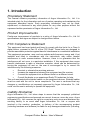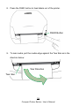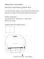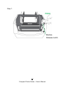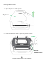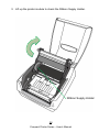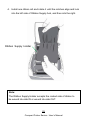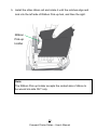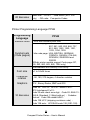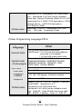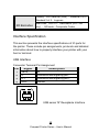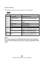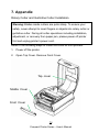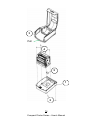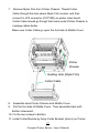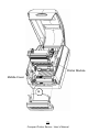
1
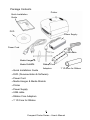
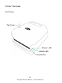
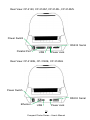
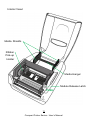
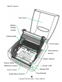
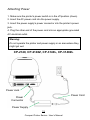
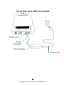
COMPACT PRINTER SERIES USER’S MANUAL CP-2140 / CP-2140Z / CP-2140E CP-3140L / CP-3140ZL CP-3140E / CP-3140LE 1 Website: http://www.argox.com Compact Printer Series - User’s Manual Table of Contents 1. Introduction................................................................... 5 Proprietary Statement ................................................... 5 Product Improvements ................................................. 5 FCC Compliance Statement ......................................... 5 Liability Disclaimer ........................................................ 5 2. Getting Started .............................................................. 7 Unpacking Printer ......................................................... 7 Package Contents .................................................... 8 Printer Overview ........................................................... 9 Front View: ............................................................... 9 Rear View: CP-2140, CP-2140Z, CP-3140L, CP-3140ZL......................................................... 10 Rear View: CP-2140E, CP-3140E, CP-3140LE ..... 10 Interior View I ......................................................... 11 Interior View II ........................................................ 12 Attaching Power ......................................................... 13 Loading Media ............................................................ 15 Preparing Media ..................................................... 15 Placing Media Roll ................................................. 15 Media Sensor Type Setting ........................................ 20 Multi-Column Label Setting by Software/ Driver ..... 20 Multi-Column Label Setting Manually ..................... 21 Loading Ribbon .......................................................... 26 Preparing Ribbon ................................................... 26 Placing Ribbon Rolls .............................................. 27 3. Printer Operations ...................................................... 32 Printing Media Calibration & Configuration ................. 32 Steps to Start Media Calibration & Configuration ... 32 Sample of Printer Configuration Label ................... 33 2 Compact Printer Series - User’s Manual Resetting Printer to Factory Defaults .......................... 35 Printer Controls and Indicators ................................... 36 Troubleshooting by LED Indicators Diagnosis ............ 39 Miscellaneous ............................................................. 42 Recovery..................................................................... 43 4. Communications ......................................................... 44 Interfaces and Requirements ...................................... 44 USB Interface Requirements .................................. 44 Serial (RS-232) Interface Requirements ................. 45 Parallel Interface Requirements.............................. 45 Serial and Parallel Cabling Requirements .............. 45 Ethernet 10/100 Internal Printer Server Option ....... 46 Ethernet Module Status Indicators .......................... 46 Communicating with the Printer .................................. 47 Installing a Plug and Play printer driver (for USB only) ........................................................................... 47 Installing a Printer Driver (for other interfaces except USB) ................................................................... 53 5. Caring for Your Printer ............................................... 61 Print Head Maintenance Guide ................................... 61 Cleaning Interval ..................................................... 61 Cleaning Material .................................................... 61 Cleaning Direction .................................................. 61 6. Product Specification ................................................. 63 General Specification .................................................. 63 Fonts, Barcodes, and Graphics Specification ............. 65 Printer Programming Language PPLA.................... 65 Printer Programming Language PPLB.................... 66 Printer Programming Language PPLZ .................... 67 Interface Specification................................................. 68 USB Interface ......................................................... 68 3 Compact Printer Series - User’s Manual Serial Interface ....................................................... 69 Parallel (Centronics) Interface ................................ 70 Ethernet Interface ................................................... 71 7. Appendix ..................................................................... 74 Rotary Cutter and Guillotine Cutter Installation ...... 74 Rotary Cutter and Guillotine Cutter Settings .......... 80 Rotary Cutter with Paper Jam ................................ 83 Guillotine Cutter with Paper Jam ............................ 84 4 Compact Printer Series - User’s Manual 1. Introduction Proprietary Statement This manual contains proprietary information of Argox Information Co., Ltd. It is intended solely for the information and use of parties operating and maintaining the equipment described herein. Such proprietary information may not be used, reproduced, or disclosed to any other parties for any other purpose without the expressed written permission of Argox Information Co., Ltd. Product Improvements Continuous improvement of products is a policy of Argox Information Co., Ltd. All specifications and signs are subject to change without notice. FCC Compliance Statement This equipment has been tested and found to comply with the limits for a Class A digital device, pursuant to Part 15 of the FCC Rules. These limits are designed to provide reasonable protection against harmful interference in a residential installation. This equipment generates, uses, and can radiate radio frequency energy and, if not installed and used in accordance with the instructions, may cause harmful interference to radio communications. However, there is no guarantee that the interference will not occur in a particular installation. If this equipment does cause harmful interference to radio or television reception, which can be determined by turning the equipment off and on, the user is encouraged to try to correct the interference by the following measures: Reorient or relocate the receiving antenna. Increase the separation between the equipment and the receiver. Connect the equipment into a different outlet on a different circuit. Consult the dealer or an experience Radio/TV technician for help. This unit was tested with shielded cables on the peripheral devices. Shielded cables must be used with the unit to insure compliance. The user is cautioned that any changes or modifications not expressly approved by Argox Information Co., Ltd. could void the user’s authority to operate the equipment. Liability Disclaimer Argox Information Co., Ltd. takes steps to assure that the company’s published engineering specifications and manuals are correct; however, errors do occur. Argox Information Co., Ltd. reserves the right to correct any such errors and disclaims any resulting liability. In no event shall Argox Information Co., Ltd. or anyone else involved in the creation, production, or delivery of the accompanying product (including hardware and software) be liable for any damages whatsoever (including, 5 Compact Printer Series - User’s Manual without limitation, damages for loss of business profits, business interruption, loss of business information, or other pecuniary loss) arising out of the use of or the results of use of or inability to use such product, even if Argox Information Co., Ltd. has been advised of the possibility of such damages. CAUTION: Any changes or modifications not expressly approved by the party responsible for compliance could void the user's authority to operate the equipment. 6 Compact Printer Series - User’s Manual 2. Getting Started Congratulations on choosing CP compact printer series, made by Argox Information Co., a leader in the world-wide barcode industry. CP compact printer series are ideally designed to easily bring more efficiency for your business. This manual will help you get to know your new printer and provide sufficient information needed. Unpacking Printer After receiving your printer, please check for possible shipping damage: Inspect the outside of both the box and the printer for possible damage. 1. Open the top cover of the printer to see if all parts are in order. Note: If shipping damage has been discovered, contact your shipping company immediately to file a claim. 2. Check whether you have received the following accessories together with the printer. If there is any item missing, please contact your local dealer. 7 Compact Printer Series - User’s Manual Package Contents Printer Quick Installation Guide DVD Power Supply Power Cord USB cable Media Hanger & Media Shields Ribbon Core Adaptors Quick Installation Guide DVD (Documentation & Software) Power Cord Media Hanger & Media Shields Printer Power Supply USB cable Ribbon Core Adaptors 1” ID Core for Ribbon 1” ID Core for Ribbon 8 Compact Printer Series - User’s Manual Printer Overview Front View: Top Cover Power LED Ready LED Feed Button 9 Compact Printer Series - User’s Manual Rear View: CP-2140, CP-2140Z, CP-3140L, CP-3140ZL Power Switch RS232 Serial Parallel Port USB Power Jack Rear View: CP-2140E, CP-3140E, CP-3140LE Power Switch RS232 Serial Ethernet Power Jack USB 10 Compact Printer Series - User’s Manual Interior View I Media Shields Ribbon Pick-up Holder Media Hanger Module Release Latch PUSH 11 Compact Printer Series - User’s Manual Interior View II Top Cover Ribbon Supply Holder Media Shaft Print Head Transmissive Sensor Media Guides Platen Roller Power LED Reflective sensor Ready LED Front Cover Feed Button Head-Open Sensor 12 Compact Printer Series - User’s Manual Attaching Power 1. Make sure the printer’s power switch is in the off position (down). 2. Insert the AC power cord into the power supply. 3. Insert the power supply’s power connector into the printer’s power jack. 4. Plug the other end of the power cord into an appropriate grounded AC electrical outlet. Warning: Do not operate the printer and power supply in an area where they might get wet. CP-2140, CP-2140Z, CP-3140L, CP-3140ZL Power Jack Power Cord Power Connector Power Supply 13 Compact Printer Series - User’s Manual CP-2140E, CP-3140E, CP-3140LE Power Jack Power Connector Power Supply Power Cord 14 Compact Printer Series - User’s Manual Loading Media Preparing Media The inside wound or outside wound media rolls can be loaded into the printer in the same way. In case media roll may become dirty or dusty during shipment, handling, or storage, firstly remove the outside length of media, which helps to avoid dragging adhesive or dirty media between the print head and platen roller. When loading media, it must be placed onto the media hangers. Placing Media Roll 1. Open Top Cover of the printer. Top Cover 15 Compact Printer Series - User’s Manual 2. Put the Media Hanger through media supply roll, and then centrally align with the two Media Shields to closely lean against the media supply roll. Media Hanger Media Shield 3. Locate the media supply roll into the Media Compartment of printer. Media Compartment 16 Compact Printer Series - User’s Manual 4. Push the Release Latch to open the printer module. PUSH Module Release Latch 5. Pull a short length of media till it reaches the Platen Roll of printer. Platen Roller 17 Compact Printer Series - User’s Manual 6. Press the lock of Media Guide at the right to adjust media guides’ positions. Make sure media stays under the Media Shaft and centrally under both of the Media Guides. Media Shaft Media Guides 7. Close the printer module and then press firmly at the both sides to properly latch until you hear a click. 18 Compact Printer Series - User’s Manual 8. Press the FEED button to feed labels out of the printer. FEED Button 9. To tear media, pull the media edge against the Tear Bar as in the direction below: Tear Direction Tear Bar 19 Compact Printer Series - User’s Manual Media Sensor Type Setting Multi-Column Label Setting by Software/ Driver To index labels with multiple columns, please select media types to Multi-Column Labels in the label editing software Bartender UL. Software setting steps: Argox Bartender UL / Seagull Driver – Media Types – Multi-Column Labels Sample of labels with multiple columns: 20 Compact Printer Series - User’s Manual Multi-Column Label Setting Manually With specific firmware versions, CP Series printers now get the sensor setting able to be achieved manually. Once there is need to detect multi-column labels, but there is no PC around, or utility software is not installed, or it’s necessary to over ride printer’s previous settings from commands/ software setting, the procedures provided below can be quick and easy to set Reflective Sensor Force Mode manually. CP Series provides two modes of media sensor type settings to set manually, with no need to connect PC and to select by software: Mode A. To always detect multi-column labels, force CP series printers to enter Reflective Sensor Force Mode. Thus, no matter which media type/ sensor type is set by Driver/ Utility/ printer commands, printer will always detect multi-column labels by its movable Reflective sensor. Steps: 1. Push the Release Latch to open the printer module. Ready LED will start flashing. 2. Press and hold Feed button for about 5 seconds, when Power LED and Ready LED start to flash alternately, the setting is complete. Release Feed button immediately. 3. In about 3 seconds, Ready LED will be flashing again. Close the printer module and then press firmly at the both sides to properly latch it until you hear a click. 21 Compact Printer Series - User’s Manual Step 1. PUSH Module Release Latch 22 Compact Printer Series - User’s Manual Step 2. FEED Button 23 Compact Printer Series - User’s Manual Step 3. Mode B. After manually setting Reflective Sensor Force Mode, if it is needed to reset the printer to its default Transmissive Sensor and exit from Force Mode, refer to the steps below: 1. Push the Release Latch to open the printer module. Ready LED will start flashing. 2. Press and hold Feed button for about 5 seconds, when Power LED and Ready LED start to flash simultaneously, the setting is complete. Release Feed button immediately. 3. In about 3 seconds, Ready LED will be flashing again. Close the printer module and then press firmly at the both sides to properly latch it until you hear a click. ※ Printer transfers between the two modes as described above. 24 Compact Printer Series - User’s Manual ※ Before printing, to double-check current sensor setting, please conduct media calibration and print a self-test/ configuration label. Refer to the sample self-test pages below: Reflective Sensor Transmissive Sensor Force Mode Mode (See-Through Sensor) 25 Compact Printer Series - User’s Manual Loading Ribbon The following steps only apply to thermal transfer printing mode only. Direct thermal does not need ribbon to be installed. Note: - Media and ribbon types should be matched to provide with optimal print results. - Always use ribbon that is wider than the media to protect the print head from wear. - For direct thermal printing, do not load ribbon in the printer. Preparing Ribbon Find the two Ribbon Core Adaptors in printer package and fix them into new ribbon rolls from the left to the right. Ribbon Core Adaptor 26 Compact Printer Series - User’s Manual Placing Ribbon Rolls 1. Open Top Cover of the printer. Top Cover 2. Push the Release Latch to open the printer module. PUSH Module Release Latch 27 Compact Printer Series - User’s Manual 3. Lift up the printer module to check the Ribbon Supply Holder. Ribbon Supply Holder 28 Compact Printer Series - User’s Manual 4. Install one ribbon roll and rotate it until the notches align and lock into the left side of Ribbon Supply hub, and then into the right. Ribbon Supply Holder Note: The Ribbon Supply Holder accepts the coated side of ribbon to be wound ink-side IN or wound ink-side OUT. 29 Compact Printer Series - User’s Manual 5. Install the other ribbon roll and rotate it until the notches align and lock into the left side of Ribbon Pick-up hub, and then the right. Ribbon Pick-up Holder Note: The Ribbon Pick-up Holder accepts the coated side of ribbon to be wound ink-side OUT only. 30 Compact Printer Series - User’s Manual 6. Close the printer module and then press firmly at the both sides to properly latch it until you hear a click. 7. Rotate Thumb Wheel of Ribbon Pick-up Holder to remove slack and ribbon wrinkle, and to align the ribbon on the spindles. Thumb Wheel 31 Compact Printer Series - User’s Manual 3. Printer Operations Printing Media Calibration & Configuration Before connecting the printer to your computer, to make sure that the printer works properly, conduct media calibration and print a self-test/ configuration label. Steps to Start Media Calibration & Configuration 1. Make sure the media is properly loaded and the top cover of the printer is closed. 2. Turn off the printer power. 3. Press and hold the FEED button while turning on the power, until printer motor is activated. 4. Media Calibration will be performed while the printer automatically feeds the label stock for a certain length; then the printer motor suspends for one second and then prints out configuration/ self-test labels. Release the FEED button as soon as printer starts to print. Note: If printer is with Argox PPLB printer language, printer will enter Dump mode after printing configuration. In Dump mode, all characters will be printed in 2 columns: the right shows characters received from your system, and the left are the corresponding hexadecimal values of the characters. It allows users or engineers to verify and debug the program. To return to normal operation mode from Dump mode, press the FEED button again. Another way is to turn off printer power, and then restart printer. 32 Compact Printer Series - User’s Manual Sample of Printer Configuration Label Firmware version & date code Memory capacity Codepage Print method Media sensor type Real Time Clock (RTC) setup (available only with RTC Card) Internal Asian fonts downloaded Printed label length Serial port settings Print speed and darkness Media type setting Print width setting Label length setting Backfeed setting Cutter setting Calibration mode type 33 Compact Printer Series - User’s Manual Ethernet information for Ethernet models only Main board DIP switch settings Print head test pattern 34 Compact Printer Series - User’s Manual Resetting Printer to Factory Defaults Follow the steps below to reset printer to default settings: 1. Turn on the printer and wait till both "Ready" indicator and "Power" indicator stay solid green. 2. Press the "FEED" button for 4 seconds, and the "Ready" indicator and "Power" indicator will go off in order. (at this step, if the “FEED” button is pressed for 8 seconds, printer will reset first >> feed blank labels as media calibration >> and then print configuration/ self-test labels.) 3. Once "Power" indicator becomes lit again, release the FEED button. 4. "Ready" indicator will then become lit, too. At this moment, the printer has resumed its factory default settings. Printer will delete those print tasks received but not yet printed. Note: The printer factory default settings are stored in printer’s flash; these settings remain stored, without being erased even the printer power is disconnected. 35 Compact Printer Series - User’s Manual Printer Controls and Indicators Power Switch Power LED Ready LED Feed Button The following table explains printer controls and indicators’ functions to help understanding LED indications and printer status: 36 Compact Printer Series - User’s Manual Control / Indicator Power Switch Function On: turns on normal operation (at “I” position) Off: turns off power ( at “O” position) Note: Turn power off before connecting or disconnecting cables Power LED It will start blinking while “Media Out”, “Media Gap Not Found” or “Ribbon Out” has been detected. Once printer cutter mode has been enabled, when Cutter is jammed with paper or Cutter is not installed, POWER indicator will blink. When RS-232 communication error is detected, POWER indicator will blink. When printer is started, the READY indicator will blink. In Ethernet model, the READY indicator will blink for several seconds to wait till Ethernet Card is ready. When printer receives data from host PC, READY indicator will start blinking. READY indicator will blink when printing is paused. It will start blinking while “Media Out”, “Media Gap Not Found” or “Ribbon Out” has been detected. It will blink as soon as the printer module is Ready LED 37 Compact Printer Series - User’s Manual opened. Note: When the print head is over-heated, printer’s thermal protection function will be activated and make READY LED blink to indicate printer is in PAUSE status to wait till print head has been cooled down. The printing tasks sent previously will be resumed automatically later. Feed Button Press to advance the label media to the first printing position. Press during printing to make printer "pause". Press and hold while switching on the power to conduct media calibration and print out a configuration profile. To resume printing after “Media Out “or “Ribbon Out “ errors have been resolved. 38 Compact Printer Series - User’s Manual Troubleshooting by LED Indicators Diagnosis Normally, when the printer is in not working properly, the "Power" LED blinks continuously, and printing and communication between the host and printer stops. Refer to LED indications listed below to understand possible solutions to resolve the problems printer run into. LED Indicators: Power and Ready LEDs blink at the same tempo Power LED Ready LED ON ON OFF OFF Possible Problems Solutions Remarks Media sensor cannot Check the label path If a continuous label roll index label gaps Check the label sensor is in use, set “continuous media” printing in driver settings or commands. Media out Install a new label roll Paper jam Recover the jam 39 Compact Printer Series - User’s Manual LED Indicators: Power and Ready LEDs blink alternately Power LED Ready LED ON OFF OFF ON Possible Problems Ribbon out Solutions Install a new ribbon roll Remarks Set “Direct Thermal” printing by driver or commands if no ribbon is required. LED Indicators: Only the Power LED blinks Power LED Ready LED ON ON OFF ON Possible Problems Solutions Remarks Serial IO error Check serial baud rate at For serial both of your system and interface only the printer. Cutter has failed, or there is paper jam inside the cutter. Check the cutter or recover paper jam. Other possible hardware errors. Contact the reseller for further service. Only applicable when cutter mode to cutter mode. 40 Compact Printer Series - User’s Manual LED Indicators: Only the Ready LED blinks Power LED ON ON Ready LED ON OFF Possible Problems Print head needs to cool down Printer head module unlatched Printer is in PAUSE status Printer is receiving data Solutions Printing will stop until the print head cools to normal printing temperature. Once it completes, the printer will automatically resume the printing tasks sent previously. Close the printer module and then press firmly at both the left and the right of printer module to properly latch. Press FEED button to resume printing. As soon as all the data has been received, Ready LED will stay solid green and automatically resume normal operation. 41 Compact Printer Series - User’s Manual Miscellaneous If the host shows "Printer Time out": 1. Check if the communication cable (serial) is connected securely to your serial port on the PC and to the connector on the printer at the other end. 2. Check if the printer power is turned on. If the data has been sent, but there is no output from the printer. Check the active printer driver, and see if Seagull driver for your Windows system and the label printer has been selected. Vertical streaks in the printout usually indicate a dirty or faulty print head. (Refer to the following examples.) Clean the print head. If the problem persists, replace the print head. 42 Compact Printer Series - User’s Manual Poor printout quality: The ribbon may not be qualified. The media may not be qualified. Adjust the Darkness (heat temperature). Slow down the print speed. Refer to the next chapter and clean the related spare parts. Recovery After correcting problems, simply press the panel button or restart the printer to continue your print jobs. Make sure the LEDs are not blinking and remember to resend your files. 43 Compact Printer Series - User’s Manual 4. Communications Interfaces and Requirements Argox CP printer series come with a nine-pin Electronics Industries Association (EIA) RS-232 serial data interface, a USB interface, Parallel, and Ethernet. A variety of interface options are suitable for versatile applications: CP-2140,CP-2140Z,CP-3140L,CP-3140ZL: Parallel, USB, and Serial interfaces CP-2140E,CP-3140E,CP-3140LE: Ethernet, USB, and Serial interfaces Note: 1. You must insert the power supply’s barrel connector into the power jack on the back of the printer before connecting communication cables. 2. This printer complies with FCC Rules and Regulations, Part 15, for Class A Equipment, for use with fully shielded six-foot data cables. Use of longer cables or unshielded cables may increase radiated emissions above Class A limits. USB Interface Requirements The Universal Serial Bus (USB) interface is compatible with your existing PC hardware. The USB’s “plug and play” design makes installation easy. Multiple printers can share a single USB port/hub. 44 Compact Printer Series - User’s Manual Serial (RS-232) Interface Requirements The required cable must have a nine-pin "D" type male connector on one end, which is plugged into the mating serial port located on the back of the printer. The other end of the signal interface cable connects to a serial port on the host computer. Note: For technical and pin-out information, please refer to the Technical Reference, Interface Specifications in this manual. Parallel Interface Requirements The required cable (IEEE 1284-compliant is recommended) must have a standard 36-pin parallel connector on one end, which is plugged into the parallel port located on the back of the printer. The other end of the parallel interface cable connects to the printer connector at the host computer. For pin-out information, refer to the Reference Technical Information, Interface Specification. Serial and Parallel Cabling Requirements Data cables must be of fully shielded construction and fitted with metal or metalized connector shells. Shielded cables and connectors are required to prevent radiation and reception of electrical noise. To minimize electrical noise pickup in the cable: 1. Keep data cables as short as possible. (6 ft or 1.83m recommended) 2. Do not tightly bundle the data cables with power cords. 45 Compact Printer Series - User’s Manual 3. Do not tie the data cables to power wire conduits. Ethernet 10/100 Internal Printer Server Option This connector is for Ethernet application; it is convenient to use several printers by Ethernet connector at the same time. Note: When using Ethernet model printer, please wait till the Ready Indicator to stop blinking, before starting printer operations. Ethernet Module Status Indicators LED Status Both Off Blinking Green Amber Description No Ethernet link detected. The printer waits for printer ready. It will take about 20 seconds to be ready. On: 100 Mbps link Speed LED Off: 10 Mbps link Link/Activity LED On: link up Off: link down Flash: activity Ethernet LED Indicators: Green LED Amber LED 46 Compact Printer Series - User’s Manual Communicating with the Printer The bundled printer driver can be applied to all applications under Windows XP/ Vista/ Windows 7/ Windows 8, supporting 32-bit/ 64-bit operation systems. With this driver you can operate any popular Windows software applications including Argox Bartender UL label editing software or MS Word, etc., to print to this printer. The following installation steps are based on CP-2140 as an example. The screens included for these steps are taken from Windows XP; steps in other versions of operation systems are similar. Drivers can be installed via the DVD included in printer package; or it can be downloaded from Argox website >> Technical Support >> Download Center >> select product model to access: http://www.argox.com/content.php?sno=0000033 Installing a Plug and Play printer driver (for USB only) Note: We strongly recommend that you use the Seagull Driver Wizard instead of the Microsoft Windows Add Printer Wizard when installing and updating your Drivers by Seagull. (Even though the "Add Printer Wizard" is from Microsoft, it too easily performs a number of tasks incorrectly when updating existing drivers. It also badly handles the situation where a printer driver is already in use by a Windows application.) 47 Compact Printer Series - User’s Manual 1. Turn off the printer. Plug the power cable into the power socket on the wall, and then connect the other end of the cable to printer's power socket. Connect the USB cable to the USB port on the printer and on the PC. 2. Turn on the printer. If the printer supports Plug-and-Play, and you have successfully connected it using a USB cable, then the Windows Add Hardware Wizard will automatically detect the printer and display a dialog that allows you to install a driver. Click Cancel and do not install the driver using this wizard. 3. Prepare the documentation and software DVD from printer package and then install to DVD drive of your computer. The DVD will bring out the following prompt. Click “Go”: 48 Compact Printer Series - User’s Manual 4. Under CP series product selection prompt, choose Seagull Driver version and then start installation: Instead of the flash prompt above, another way to install Seagull driver is to run the DriverWizard utility from the Installation Directory where the Seagull driver files are located. 49 Compact Printer Series - User’s Manual 5. On the Seagull Driver Wizard prompt, select the first radio button to “Install a driver for a Plug and Play printer”: Then click “Next.” 6. Enter Printer name (i.e. Argox CP-2140 PPLB) and select "do not share this printer”, and click "Next" 50 Compact Printer Series - User’s Manual 7. Check all the data on the showing screen, if it is correct, click "Finish". 8. After the related files have been copied to your system, click "Finish". 51 Compact Printer Series - User’s Manual 9. After driver installation is complete, click "Close". The driver should now be installed. 52 Compact Printer Series - User’s Manual Installing a Printer Driver (for other interfaces except USB) 1. Turn off the printer. Plug the power cable into the power socket on the wall, and then connect the other end of the cable to printer's power socket. Connect the Parallel cable, Serial cable, or Ethernet cable to the proper port on the printer and on your computer. 2. Prepare the documentation and software DVD from printer package and then install to DVD drive of your computer. The DVD will bring out the following prompt. Click “Go”: 53 Compact Printer Series - User’s Manual 3. Under CP series product selection prompt, choose Seagull Driver version and then start installation: Instead of the flash prompt above, another way to install Seagull driver is to run the DriverWizard utility from the Installation Directory where the Seagull driver files are located. 54 Compact Printer Series - User’s Manual 4. On the prompt, Windows Printer Driver, select “I accept…” and click "Next". 5. Assign the directory to keep Seagull driver, (for example: C:\Seagull) and click "Next". 55 Compact Printer Series - User’s Manual 6. Click "Finish". 7. Select Install printer drivers and Click "Next" 56 Compact Printer Series - User’s Manual 8. Make sure printer is connected to PC, select “Other” and click “Next”: 9. Select model & emulation - the following examples are based on model CP-2140 PPLB: 57 Compact Printer Series - User’s Manual 10. Select the port of the printer and click "Next". 11. Enter Printer name (i.e. Argox CP-2140 PPLB) and select "do not share this printer”, and click "Next". Argox CP-2140 PPLB 58 Compact Printer Series - User’s Manual 12. Check all the data on the showing screen, if it is correct, click "Finish". 13. After the related files have been copied to your system, click "Finish". 59 Compact Printer Series - User’s Manual 14. After driver installation is complete, click "Close". The driver should now be installed. 60 Compact Printer Series - User’s Manual 5. Caring for Your Printer Print Head Maintenance Guide To keep the Print Head remain in the best conditions and efficiency and to extend duration for use, regular cleaning action is needed: Note: Always switch off printer power before cleaning. In case of long-time printing, surface of print head may be very hot. Please wait till print head cools down properly before maintenance, to prevent burns. During maintenance, do not directly touch print head surface, to avoid its damage and any possible injury to you. Use cleaning material instead. Cleaning Interval It’s strongly recommended to regularly clean print heads at least when changing every one label roll (in direct thermal printing mode) or every one ribbon roll (in thermal transfer printing mode). In addition, if printers are operated under critical applications and environments, or if it’s found that print quality is degraded, please clean print heads more frequently. Cleaning Material Surface of print head’s heating element is very fragile. To prevent from any possible damage, please use soft cloth/ cotton buds with “Ethanol” or “IPA” to clean print head surface. It’s strongly recommended to wear hand gloves during cleaning progress. Do not touch print head surface by bare hands or with any hard equipment. Water or spit should be kept away in case of corrosion on heating elements. Cleaning Direction 61 Compact Printer Series - User’s Manual When cleaning the print head, always wipe in One-Way Direction - from Left to Right only, or, from Right to Left only, to clean “Heating Line” of print head gently without excessive stress. Do not wipe back and forth, to avoid dust or dirt on cleaning cotton would be attached onto print head again. Special Caution: Warranty of print heads will be void if print head serial number is removed, altered, defected, or made illegible, under every circumstance. 62 Compact Printer Series - User’s Manual 6. Product Specification General Specification Specifications Printing Method Printing Resolution Printing Speed Printing Length Printing Width Memory CPU Type Sensors Operation Interface Communication Interface Emulation Software - CP-2140 CP-2140E CP-3140L CP-3140E CP-3140LE Direct Thermal / Thermal Transfer 203 dpi(8 dots/mm) 2~4ips (50.8~101.6mm/s) Max 100”(2540mm) Min 0.2”(5mm) Max 4.1”(104mm) 300 dpi (12 dots/mm) 1~up to 4ips (25.4~101.6 mm/s) Max 50”(1270mm) Min 0.2”(5mm) 8MB DRAM (5MB user 8MB DRAM (5MB user available) available) 4MB Flash ROM (2MB user available) 8MB Flash ROM (6MB user available) 32 bit RISC microprocessor Media Reflective sensor x 1 (movable) & Media Transmissive sensor x 1 (Center fixed) / Head open switch / Ribbon end sensor LED indicator (Power/Ready)x 2, Button(Feed) x 1 CP-2140, CP-3140L: Parallel, RS-232(Baud rate: 2400~115200 bps), USB CP-2140E, CP-3140E, CP-3140LE: Ethernet, RS-232(Baud rate: 2400~115200 bps), USB CP-2140, CP-2140E, CP-3140L, CP-3140E, CP-3140LE: PPLA, PPLB CP-2140Z, CP-3140ZL: PPLZ Seagull Driver, BarTender 63 Compact Printer Series - User’s Manual Label editing Software – Utility Media Type Media Ribbon Dimensions Weight Power Source Operation Environment Media Stacker Optional Items Agency Listing Printer Utility, Font Utility Roll-feed, die-cut, continuous, fan-fold, tags, ticket in thermal paper or plain paper and fabric label Max Width:4.33”(110mm) Min Width:1”(25.4mm) Thickness:0.0025”~0.01”(0.0635~0.254mm) Max roll capacity(OD):5”(127mm) Core size:1”(25.4mm) / Max roll capacity(OD):4.5”(114.3mm) Core size:0.5”(12.7mm) (optional) / Max roll capacity(OD):4.72”(120mm) Core size:1.5”(38.1mm) (optional) Min Length: 0.79“(20mm) for rotary cutter option Ribbon roll – max OD: 2.6”(67mm) Ribbon Length: max 300m Core size – ID: 1”(25.4mm) Ribbon Width: 1”~4”, Wax, Wax/Resin, Resin (Ribbon wound ink-side out or ink-side in) L 273mm x W 225mm x H 186mm 2.1kg Universal Switching Power Universal Switching Power Supply Supply Input: 100~240V,1.8A, Input: 100~240V,1.5A, 50-60Hz, 50-60Hz, Output: 24VDC, 2.4A Output: 24VDC, 2.91A Operation Temperature: 40F~100F (4C~38C), 10% ~ 90% non-condensing, Storage Temperature: -4F~122F (-20C~50C) Optional: CP-2140, CP-2140E, CP-3140L, CP-3140LE Standard: CP-3140E Cutter, RTC Card, ArgoKee CE, FCC, cTUVus, CCC, RoHS 64 Compact Printer Series - User’s Manual Fonts, Barcodes, and Graphics Specification The specifications of fonts, bar codes and graphics depends on the printer emulation. The emulations PPLA, PPLB, and PPLZ are printer programming languages, through which the host can communicate with your printer. Printer Programming Language PPLA Programming Language PPLA 9 fonts with different point size Internal fonts 6 fonts with ASD smooth font. Symbol sets (Code pages) Soft fonts Courier font with different symbol sets. Courier font symbol set: Roman-8, ECMA-94, PC, PC-A, PC-B, Legal, and PC437 (Greek), Russian. Downloadable soft fonts by Font Utility Font size 1x1 to 24x24 times Character rotation 0, 90, 180, 270 degree, 4 direction rotation Graphics PCX, BMP, IMG, GDI and HEX format files 1D Barcodes Code 39、UPC-A、UPC-E、Code 128 subset A/B/C、EAN-13、EAN-8、HBIC、Codabar、Plessey、 UPC2、UPC5、Code 93、Postnet、UCC/EAN-128、, UCC/EAN-128 K-MART、UCC/EAN-128 Random weight、Telepen、FIM、Interleaved 2 of 5 (Standard/with modulo 10 checksum/ with human readable check digit/ with modulo 10 checksum & shipping bearer bars) 、GS1 Data bar (RSS) 65 Compact Printer Series - User’s Manual 2D Barcodes MaxiCode、PDF417、Data Matrix (ECC 200 only) 、QR code、Composite Codes Printer Programming Language PPLB Programming PPLB Language Internal fonts 5 fonts with different point size Symbol sets (Code pages) Soft fonts 8 bits code page : 437, 850, 852, 860, 863, 865, 857, 861, 862, 855, 866, 737, 851, 869, 1252, 1250, 1251, 1253, 1254, 1255 7 bits code page: USA, BRITISH, GERMAN, FRENCH, DANISH, ITALIAN, SPANISH, SWEDISH and SWISS (300dpi printer models support Code page 437, 850, 852, 860, 863, 865, 1254 only) Downloadable soft fonts by Font Utility Font size 1x1 to 24x24 times Character rotation 0, 90, 180, 270 degree, 4 direction rotation Graphics PCX , Binary Raster, BMP and GDI 1D Barcodes Code 39、UPC-A、UPC-E、Matrix 2 of 5、 UPC-Interleaved 2 of 5、 Code 39 with check sum digit 、Code 93、EAN-13、 EAN-8 (Standard, 2 /5digit add-on) 、Codabar、 Postnet、Code128 subset A/B/C、 Code 128 UCC (shipping container code) 、 Code 128 auto、UCC/EAN code 128 (GS1-128) 、 66 Compact Printer Series - User’s Manual 2D Barcodes Interleave 2 of 5、Interleaved 2 of 5 with check sum、Interleaved 2 of 5 with human readable check digit、German Postcode、Matrix 2 of 5、UPC Interleaved 2 of 5、EAN-13 2/5 digit add-on、UPCA 2/5 digit add-on、UPCE 2/5 digit add-on、 GS1 Data bar (RSS) MaxiCode、PDF417、Data Matrix (ECC 200 only) 、QR code、Composite Codes Printer Programming Language PPLZ Programming Language Internal fonts Symbol sets (Code pages) Soft fonts Font size Character rotation Graphics 1D Barcodes PPLZ 8 (A~H) fonts with different point size. 8 AGFA fonts: 7 (P~V) fonts with fixed different point size (not scalable). 1 (0) font with scaling point size. USA1, USA2, UK, HOLLAND, DENMARK/NORWAY, SWEDEN/FINLAND, GERMAN, FRANCE1, FRANCE2, ITALY, SPAIN, MISC, JAPAN, IBM850 Downloadable soft fonts by Font Utility 1x1 to 10x10 0, 90, 180, 270 degree, 4 direction rotation GRF, Hex and GDI Code39、UPC-A、UPC-E、Postnet、Code128 subset A/B/C、Interleave 2 of 5、 Interleaved 2 of 5 with check sum、 Interleaved 2 of 5 with human readable check digit、Code 93、Code 39 with check sum digit、 MSI、EAN-8、Codabar、Code 11、EAN-13、 67 Compact Printer Series - User’s Manual 2D Barcodes Plessey、GS1 Data bar (RSS) 、Industrial 2 of 5、 Standard 2 of 5、Logmars MaxiCode、PDF417、Data Matrix (ECC 200 only) 、QR code、Composite Codes Interface Specification This section presents the interface specifications of IO ports for the printer. These include pin assignments, protocols and detailed information about how to properly interface your printer with your host or terminal. USB Interface Connector Terminal Pin Assignment Pin 1 2 3 4 Signal Description VBUS 5V D- Differential data signaling pair - D+ Differential data signaling pair + GND Ground 2 1 3 4 USB series “B” Receptacle Interface 68 Compact Printer Series - User’s Manual Serial Interface The RS232 connector on the printer side is a female, DB-9. Pin 1 2 3 4 5 6 7 Signal No function Received Data, RxD Transmitted Data, TxD No function GND No function Request to Send, RTS 8 Clear to Send, CTS 9 +5V Description Shorted to Pin - 6 Input. Serial “Received Data” Output. Serial “Transmitted Data”. No connection Signal Ground Shorted to Pin - 1 Output. Used as the control signal for “H/W Flow Control “ Input. Used as the control signal for “H/W Flow Control” Output. Pin 9 is reserved for KDU (keyboard device unit) Note : Pin 9 are reserved for KDU (keyboard device unit), therefore do not connect these pins if you are using a general host like a PC. 69 Compact Printer Series - User’s Manual Parallel (Centronics) Interface The parallel port is a standard 36-pin Centronics, which complies with IEEE 1284 standard (compatibility mode). Pin assignments are as follows: Pin Direction Definition Pin Direction Definition 1 In /STROBE 13 2 In Data1 14,15 3 In Data 2 16 - Ground 4 In Data3 17 - Ground 5 In Data4 18 6 In Data5 19~30 - Ground 7 In Data6 31 8 In Data7 32 Out /Fault 9 In Data8 33~36 - NC 10 Out /ACK 11t Out BUSY 12 Out PE Out SELECT NC NC Auto Polling Both the serial port and parallel port of this printer can be activated at the same time, i.e the printer can simultaneously communicate with two PCs via different ports. However as no port contention is made for this printer, if both PCs transmit data at the same time the data may become damaged in the receiving buffer. 70 Compact Printer Series - User’s Manual Ethernet Interface The following port complies with Ethernet communication. Pin 1 2 3 4 5 6 7 8 Signal Transmit+ TransmitReceive+ Reserved Reserved ReceiveReserved Reserved 1234567 8 71 Compact Printer Series - User’s Manual Connection with Host Host 25S Printer 9P (PC or compatible) Host 9S Printer 9P (PC or compatible) DTR 20 DSR 6 TX 2 …… 1 DSR …… 6 DTR …… 2 RX DTR 4 DSR 6 TX 3 …… 1 DSR …… 6 DTR …… 2 RX RX 3 CTS 5 RTS 4 GND 7 …… …… …… …… RX 2 CTS 8 RTS 7 GND 5 …… 3 TX …… 7 RTS …… 8 CTS …… 5 GND 3 TX 7 RTS 8 CTR 5 GND Alternatively you can just connect the 3 wires in the following way. Host 25S Printer 9P Host 9S (PC or compatible) Printer 9P (PC or compatible) TX 2 …… 2 RX RX 3 …… 3 TX GND 7 …… 5 GND TX 3 …… 2 RX RX 2 …… 3 TX GND 5 …… 5 GND pin 4 pin 5 pin 6 pin 20 pin 4 pin 6 pin 7 pin 8 72 Compact Printer Series - User’s Manual The simplest way to connect to other hosts (not PC compatible) or terminals is: Printer Terminal/Host Pin 2- RxData ……… TxData Pin 3- TxData ……… RxData Pin 5- Ground ……… Ground In general, as long as the data quantity is not too large and you use Xon/Xoff as flow control, it will be problem free. Baud rate: 2400, 4800, 9600(default), 19200, 38400, 57600, 115200 bauds.(programmable by command) Data format: always 8 data bits, 1 start bit and 1 stop bit. Parity: always non parity Handshaking: XON/XOFF as well as CTS/RTS (hardware flow control). If you run an application with the bundled printer driver under Windows and use the serial port, you should check the above parameters and set the flow control to "Xon/Xoff "or "hardware". 73 Compact Printer Series - User’s Manual 7. Appendix Rotary Cutter and Guillotine Cutter Installation Warning: Blades inside cutters are quite sharp. To ensure your safety, never attempt to insert fingers or objects into rotary cutter or guillotine cutter. During all cutter operations including installation, adjustment, or recovery from paper jam, please power off printer first and unplug printer’s power cord. Refer to the following steps to install the cutter kit onto printers: 1. Power off the printer. 2. Open Top Cover. Remove Front Cover. Top cover Middle Cover Front Cover 74 Compact Printer Series - User’s Manual 3. Loose the two screws (item 2) under Bottom (item 1). 4. Pull out to unlatch the front side of Middle Cover (item 3) and then remove it upward from Bottom . 5. Loose the four screws (item 4) at both sides of Printer Module to take Printer Module off from Bottom. 6. Find Cutter Baby Board in cutter package (item 5), and then install onto JP16 socket on printer main board. 75 Compact Printer Series - User’s Manual 3 Pull 4 5 1 2 76 Compact Printer Series - User’s Manual 7. Remove Mylar Film from Printer Chassis. Thread Cutter Cable through the hole where Mylar Film locates, and then connect to JP9 connector (CUTTER) on printer main board. Cutter Cable should go though the hooks under Printer Chassis to manage cables better. Make sure Cutter Cable go upon the font side of Middle Cover. Printer Chassis Guiding Hole (Mylar Film) Cutter Cable 8. Assemble back Printer Chassis and Middle Cover. 9. Pull the font side of Middle Cover. Then assemble back with Bottom downward. 10. Fix the two screws to Bottom. 11. Install Cutter Module by fixing Cutter Bracket (item 6) on Printer 77 Compact Printer Series - User’s Manual Chassis with screws. 12. Close Printer Module and Top Cover. Now cutter installation has been completed through the steps above. To load media, please refer to the section – Loading Media. 78 Compact Printer Series - User’s Manual Printer Module Middle Cover 6 79 Compact Printer Series - User’s Manual Rotary Cutter and Guillotine Cutter Settings Before printing and cutting tasks, please make sure whether the cutter in use is Rotary Cutter, or Guillotine Cutter. Then select proper settings via Seagull Driver for printer. The following installation steps are based on CP-2140 as an example. 1. Check CP-2140 driver. Go to the prompt of Printer Properties, click on the tag, “Tools’: 2. Click the “Configure” setting of driver, select “Cutter Setup”: 80 Compact Printer Series - User’s Manual 3. “Cutter Setup” prompts will be indicated as below. Check on the radio button, “Rotary” if there’s Rotary Cutter installed. Then click “OK“: Check on the radio button, “Guillotine” if there’s Guillotine Cutter installed. Then click “OK“: 81 Compact Printer Series - User’s Manual 4. Go to “Printing Preference” prompt of CP-2140 driver and then click on the “Stock” tag. Check “Post-Print Action” settings and select “Cut”. ※ If there’s Guillotine Cutter installed and partial cut function is needed, select “Partial Cut” in “Post-Print Action”. 82 Compact Printer Series - User’s Manual Rotary Cutter with Paper Jam If there is paper jam inside rotary cutter, refer to Rotary Cutter Installation section to remove the rotary cutter. Check the Cam as marked in Figure 1; find a slotted screwdriver to turn counter-clockwise as Figure 2. During turning the Cam of cutter, release the blade from paper and them remove the paper from the cutter. Figure 1. Figure 2. 83 Compact Printer Series - User’s Manual Guillotine Cutter with Paper Jam If there is paper jam inside guillotine cutter, check in Figure 2 and find where the screw under guillotine cutter. It is to control cut actions of guillotine cutter. Find a Phillips screwdriver to lay down the blade by turning the screw as directions marked in the figures. Then paper can be removed from the cutter. Figure 1. Figure 2. Guillotine Cutter with full cut function: Turn counter-clockwise. Guillotine Cutter with partial cut function: Turn clockwise. 84 Compact Printer Series - User’s Manual