1
RIKKE-MATHILDA
microassemblers and simulators
on the DECSystem-10
by
Ib Holm S0rensen
and
Eric Kressel
DAIMI MD-28
December 1977
Mltomltllk Inltltut
, Airhul UnlYlrlltlt
DATALOGISK AFDELING
Ny Munklglde - 8000 Airhul C - Dlnmlrk
Tlf.06-128355
List of Contents.
O. Introduction
3
1. The Micro Assembly Language
1.1 Label field
1.2 Bus field
1.3 Microoperation and data field
1.4 Sequencing field
1.5 Comments
4
4
2. The Assembler Pseudo Instructions
2.1
2.2
2.3
2.4
2.5
*Manifest or *M
*Binary or *B
*Origin or *0
* Radix or * R
*Xternal or *X
2.6 *List or *L
2.7 *Nolist or *N
2.8 *Page or *P
2.9 **
2.10 *Table or *T
2.11 *Display or *D
2.12 *Entry or *E
2.13 *Value or *V
2.14 *Snooper or *S
5
6
7
11
12
13
14
15
15
16
16
17
17
17
17
20
20
21
23
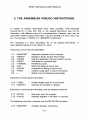
3. The Simulators
3.1 Port A
3.2 Port B
3.3 Port C
24
25
25
4. Using the Systems
4.1 Conventions
4.2 Summary of Options
4.3 Examples of Command Sequences
4.4 Programming and Simulation Examples
32
32
34
39
39
List of References
46
29
- 1-
INTRODUCTION
Section 0
O. INTRODUCTION.
This document describes the use of the simulated RIKKE and MATHILDA
systems which are implemented in the programming language BCPL [1] and are
operating on the DECsystem-l0 in the Department of Computer Science at
Aarhus University.
Each system consists of a simulator that reflects the hardware of a physical
machine (either RIKKE-l [2],[3] or MATHILDA [4],[5]), and a microassembler
(named MARIA and LOUISE, respectively) that is capable of either producing
an interface file for simulation or object code paper tape for the physical
machine.
The simulator of RIKKE-l is a software copy of the physical machine. Results
obtained from the construction of RIKKE-l caused some design extensions and
changes which have been implemented in MATHILDA. Furthermore,
MATHILDA has facilities which are only in the design stage. To provide a basis
for experiments with these novelties the simulator of MATHILDA not only
copies the present hardware but also the designed extensions.
References [2] and [4] are solid foundations of the systems and must be
regarded as the tutorial description of the microassembly language and the
machines that are simulated. In the following we therefore presuppose a
knowledge obtained from reading those references.
In section 1 we give a summary of the syntax and semantics of the
microassembly language as it is described in [2] and [4]. Section 2 contains a
description of the pseudo instructions available in the microassemblers. Some
of them apply to the simulators which are the topic of section 3. Finally section
4 describes how to run the systems on the PDP-l0.
-3-
RIKKE-MA THILDA USER MANUAL
1. THE MICRO ASSEMBLY LANGUAGE.
A program written in RIKKE-MATHILDA micro assembly language consists of
a sequence of microinstructions and pseudoinstructions. This section describes
the format of a microinstruction and the next section discusses available
pseudoinstructions.
A microinstruction can be divided into 4 fields:
<label> <buS> ; <mop & data> ; <sequencing> .
where" mop" is an abbreviation of "microoperation". In the following, when
talking about an "instruction", we mean a "microinstruction".
Each instruction must occupy exactly 1 line. The instruction may be terminated
by a period (.) in which case all characters following the period on the rest of
the line are interpreted as a comment and skipped by the micro assemblers.
1.1 Label field.
The syntax of the <label> field is:
<label> :: = <identifier> :
<identifier> is a string of alphanumeric characters of which the first 15 are
significant and the first character must be a letter. The <label> field may be left
empty. Further details on the use of labels are given in section 1.4 which
discusses the sequencing field.
-4-
ASSEMBLY LANGUAGE
Section 1
1.2 Bus field.
The syntax of the <buS> field is:
a.
b.
c.
d.
e.
<empty>
<source>
<source> ,<bus shift spec>
<destination list>: = <source>
<destination list>: = <source>,<bus shift spec>
Furthermore, LOUISE accepts three additional formats:
f.
g.
h.
<destination list>: = ALL 1 S
<destination list>: = ALL 0 S
<destination list>: = <constant>
<source> describes the input to a Main Data Path transport, <destination list>
where the result of the transport is to be stored and <bus shift specification>
indicates how the data of the transport is to be handled by the Bus Shifter.
The <mop & data> field is divided into subfields (see the next subsection) and
format f occupies subfield F1. Format g similarly occupies subfield F3. Thus
formats f and g require that the micro programmer does not use subfields F1
and F3, respectively, of the <mop & data> field for other purposes.
In format h, <constant> is an integer or a manifest constant (see section 2.1).
Format h occupies subfields F2, F3 and S3 of the <mop & data> field.
Additionally, format h assumes that the Status Port Pointer, SPP, has been
cleared previously.
The <bus shift spec> part can be written as follows:
1.
2.
3.
4.
<bus
<bus
<bus
<bus
shift
shift
shift
shift
spec>::=
spec>:: =
spec>:: =
spec>:: =
'<'
'>'
'<' <constant>
'>' <constant>
In formats 1 and 2, the direction of '<' and '>' is not significant. The use of '<'
and '>' merely indicate that the Bus Shifter is enabled. Bus Shifter data in such
cases is usually taken from sources other than the current instruction.
In formats 3 and 4, the direction of '<' and
-5-
'>'
is significant. The data on the
RIKKE-MA THILDA USER MANUAL
Main Data Path is shifted in the direction indicated (left or right, respectively) by
the number of bit positions given by <constant>. <constant> may be an
integer or a manifest constant (see section 2.1).
1.3 Microoperation and data field.
The <mop & data> field is divided into subfields that are shared by
microoperations and data from other fields of the instruction. The micro
programmer must be aware of this or various conflicts will arise. For further
details on these matters, we refer our reader to references [3] and [5].
In a symbolic microinstruction the micro programmer need not specify which
subfield he wants filled. This is handled by the micro assemblers. Items for the
<mop & data> field are as a list separated by commas. Generally, four types of
item~ can be placed in the <mop & data> field:
a.
b.
c.
d.
e.
<mop>
<mop> <source specification>
<mop> <data>
<shifter op>
<PG data>
Type a will occupy 1 subfield. Type d will occupy the shifter fields of the
microinstruction. The number of subfields occupied by other types vary. Precise
information on this is found in references [3] and [5].
Examples:
Type a:
CA+ 1, WBU-1
Type b:
WAG:=SG, WAU:=SB
Type c:
IBD: = 10, ALF: = A + B + 1
Type d:
AS<,VS>, DS<
Type e:
PG< 12
Microoperations, microoperation data and data belonging to bus shifting and
address sequencing must share the subfields of the <mop & data> field. Data
not originating in microoperations, such as bus shifting data or address
constants, are not explicitly written in the <mop & data> field. However, to let
-6-
ASSEMBLY LANGUAGE
Section 1
the programmer indicate that he actually has used a subfield for other things,
the assemblers accept the quote (") character as a blind character. Thus the
programmer can overwrite a used subfield with a block of quotes.
Examples:
WA:= ALL 1 S;
WAU+1
PG>2 ""Un"
VS:= WA,>2;
"""""; R-2
When the assembler is packing an instruction, it tries to push everything in
without causing any conflicts. So sometimes the assemblers might re-arrange
the instruction as it was written symbolically. If the assembler cannot resolve
all problems it gives up and emits an appropriate error message.
1.4 Sequencing field.
The address of the microinstruction to be executed next is specified in the
<sequencing> field and can be written as follows:
a.
b.
c.
d.
<empty>
<addrt>
IF <c> THEN <addrt>
IF <c> THEN <addrt> ELSE <addrf>
e.
f.
IF NOT <c> THEN <addrf>
UNLESS <c> THEN <addrf>
g.
h.
IF NOT <c> THEN <addrf> ELSE <addrt>
UNLESS <c> THEN <addrf> ELSE <addrt>
Formats e and g are equivalent to f and h, respectively.
The <sequencing> field must be preceded by a semicolon; if the <mop & data>
field is empty, <sequencing> must be preceded by two semicolons.
Which microinstruction to be executed next can be dependent on some
condition <c>. If the condition is true, the address specification given by
<addrt> is followed, otherwise the address specification <addrf> is valid.
The various formats apply some conventions which are given in the following.
-7-
RIKKE-MATHILDA USER MANUAL
Format a:
<addrt> and <addrf> are both set to HERE + 1.
Format b:
If the address mode involves the Control Unit ALU (CUAL) or
return jump stack (RA or RB), the selected condition field of the
microinstruction is set to true and the address mode
specification is entered in <addrt>. OtherWise the selected
condition field is left untouched and both <addrt> and <addrf>
are set according to the specification.
Format c:
<addrf> is set automatically to HERE + 1.
Formats d, g and h:
If the CUAL is used in <addrt> it may also be used in <addrf>,
provided that the B-input data to the CUAL is the same and the
use will not give rise to a carry-in conflict. See references [3]
and [5] in the sections on sequencing.
Formats e and f:
<addrt> is set automatically to HERE + 1.
HERE denotes the location of the current microinstruction.
1.4.1 Using the various address modes.
The CUAL, RA and RB take data from the <mop & data> field of the
microinstruction being processed. This data is called the B-input. It is used
when the sequencing mode of a microinstruction is
a.
b.
c.
a branch to an absolute location.
a branch to a relative location.
a return jump through a return jump stack.
Mode a is applied when the CUAL function selector (CUALF) is set to the B
function. (This is done with the microoperation Set CUALF to B SCUALF B.) The absolute location is denoted by a constant or a label. The
constant can be an unsigned integer or a manifest constant (see section 2.1).
-8-
ASSEMBLY LANGUAGE
Section 1
Examples of instructions assuming the CUAL is set to the B function:
WA;
WAGS:=WAG,WBPC ;FETCH
After execution of this instruction, the microinstruction labelled FETCH will be
processed.
IB;
SA:=SB
;IF IBOA THEN 497 ELSE HERE.
The instruction will loop in itself until data has been read from Input port B (lB).
Then the program will branch to location 497.
Mode b is enabled when the CUAL function selector is set to the A + B
function. (This is done with the microoperation Set CUALF to + SCUALF +.) All locations in Control Store may be addressed relatively. There
are two ways of doing it:
1. When a constant (integer or manifest, see section 2.1) is preceded by "R + "
or "R-", the assemblers place the value of the constant in the appropriate
data field as B-input, and signs it according to the sign following "R·.
2. When "R +" or "R-" precedes a label, the assemblers calculate the signed
difference between the location labelled and the current location and places
the result as B-input. Thus the use of" +" or "-" is insignificant.
LOUISE has the additional facility:
3. When "R + SA", "RA + SA" or "R B + SA" is written as an address
specification, LOUISE selects a special sequencing mode, where the six
least significant bits of the SA register are used as B-input. No data is
placed in the <mop & data> field.
Some examples:
;IF WA(Q) THEN R + LOOP ELSE R + LOOP + 1
Assume LOOP is a label. Then, if the condition WA(O) is true (j.e. bit 0 of the
current WA register in the previous instruction equalled 1), execution will
branch to the location labelled by LOOP. If the condition is false, the
microinstruction immediately succeeding the instruction labelled by LOOP is
processed.
-9-
RIKKE-MA THILDA USER MANUAL
;IF NOT BUS THEN R-LAB.
Assume LAB is a manifest constant (see section 2.1) with the associated value
15. Then, ifthe condition BUS is false (i.e. the contents of the Main Data Path
in the previous instruction were not all zeroes), execution continues at location
HERE + 15. If the condition is true, the microprogram continues at location
HERE+ 1.
;R+312.
Assume that the location of the current microinstruction is 2. Then execution is
resumed at location 314.
In mode c the .B-input i~.adrjed to the contents of the top element of a
specified Return Jump'''Stad<'to yield the effective address. Applying mode c
also pops the Return Jump Stack.
Examples:
;RA+ 12
Execution continues at the address computed by adding 12 to the contents of
the top element of the RA stack.
;RA+1
This example is important. In this situation the assemblers force the data to zero
and set the carry-bit, thus freeing data fields for other requirements.
The assemblers place the B-input data in the data subfields as follows:
If the data is zero, no data fields are occupied. If the data is in the range
[-32,31] (excluding zero), only subfield F4 is occupied by B-input data.
In all other cases, both subfields F3 and F4 are occupied by the
addressing data.
Notice that
- 10-
ASSEMBLY LANGUAGE
Section 1
- the notations "HERE" and "R" are equivalent and may be interchanged to
suit the user.
- the assemblers do not distinguish between forward referenced labels and
backward referenced labels.
1.4.2 Summary of addressing modes.
(a)
Branch to a labelled location:
1. With CUALF set to the B function, e.g.
; LABEL
2. With CUALF set to A + B function, e.g ..
; R+LABEL
; R-LABEL
(b)
Branch to an absolute location:
1. With CUALF set to the B function, e.g.
; 1052
2. With CUALF set to the A + B function, e.g.
; R-7
1.5 Comments.
Each microinstruction may optionally contain a comment. A comment is
inserted in the microcode by preceding it with a period (.). The assemblers
ignore any characters between the period and the new-line. The user is
cautioned to be careful in his use of periods in his program text.
Examples:
.This is a comment line
;HERE + 1 . dummy instruction
- 11 -
RIKKE-MA THILDA USER MANUAL
2. THE ASSEMBLER PSEUDO INSTRUCTIONS.
A number of pseudo instructions have been provided. Their keywords
must all start on a new line; that is, the pseudo instructions may not be
intermixed with different parts of a microinstruction. However, they may be
used within another pseudo instruction, if its text spreads over more than one
line (for example, a *RADIX in a *MANIFEST instruction).
The following is a short descriptive list of the pseudo instructions. A
more detailed treatment is then given for each.
Instructions concerning the assemblers:
2.1
2.2
2.3
2.4
2.5
2.6
2.7
2.8
2.9
*MANIFEST
*BINARY
*ORIGIN
*RADIX
*XTERNAL
*LlST
*NOLIST
*PAGE
**
Associates identifiers with constants.
Displays a binary Control Store image.
Sets the assembler's internal location counter.
Sets base for numerical data.
Predefines a label.
Starts the listing of source text.
Suspends the listing of source text.
Creates a page eject in source text listing.
Writes a line of asterisks across listing.
Instructions concerning the simulators:
2.10 *TABLE
2.11 *DISPLAY
Creates display table for the simulator
Instructs the simulator to display
Instructions concerning the simulators and the physical machines:
2.12 *ENTRY
2.13 *VALUE
Sets entry point for program.
Initialises registers in simulator or machine.
The following instruction concerns only the MATHILDA simulator:
2.14 *SNOOPER
Initialises Snooper instructions.
- 12-
PSEUDO INS TRue nONS
Section 2
2.1 *MANIFEST or *M:
Format:
*MANIFEST
<definition list>
END
where <definition list> is a list of items with the following format:
<name> = <value>
separated by semicolons or new-lines. <name> is a string of alphanumeric
characters of which the first 15 are significant and the first character is a letter.
<value> is an integer or a manifest.
This instruction permits the user to associate names with certain constants, i.e.
a manifest may be used in a microprogram to denote the constant
associated with it.
There are some restrictions to be observed:
1.
2.
A manifest may only be used in instructions following its definition.
The terminating END must not be omitted.
Note that a label which has been defined prior to a given microinstruction
may also be used as a manifest, and will have the value of the Control Store
location for which it is a label. However, the user must be aware of the
difference between the use of a label and a manifest constant in relative
addressing (see Section 1.4). Keeping this restriction in mind, a
*MANIFEST statement may be placed anywhere in a program.
- 13-
RIKKE-MA THILDA USER MANUAL
Examples:
*MANIFEST
CONTEXTBLOCK = 3
END
LAB:
;WAG: = CONTEXTBLOCK
After execution of the instruction labelled LAB, the Working register A (WA)
group indicator is set to 3.
*MANIFEST
PTR
10
PRINTER = 3
LOOKUP = 5
END
IBO : = PTR
OBO : = PRINTER,
IBA
.sets input port B device selector to 10
.sets output port B device selector to 3
;IF IBOA THEN R-LOOKUP ELSE HERE
.The last instruction will loop in itself until
.data is available from lB .
.The program then branches to HERE-5.
HERE
denotes
microinstruction.
as
the
usual
location
of
the
current
2.2 *8INARY or *8:
Format:
*BINARY : <Ioc 1> - <Ioc 2> or
*BINARY : <Ioc 1>
where <Ioc 1> and <Ioc 2> are unsigned integers or manifests.
If the program contains one or more (up to 25) *BINARY instructions,
the assembler will, after listing the program and any diagnostics, display a
- 14-
PSEUDO INS TRue nONS
Section 2
Control Store image in binary format in the range from location <Ioc 1> to
location <Ioc 2>, or if the second format is used, only location <Ioc 1>.
*BINARY may be placed anywhere in a program. An example using the
2.3 *ORIGIN or *0:
Format:
*ORIGIN
= <constant>
where <constant> may be an unsigned integer or manifest. This instruction
sets the assembler's internal location counter to the value of <constant>. The
sequence of microinstructions following an *ORIGIN pseudo instruction
will be assembled starting at the address given. A *ORIGIN instruction may be
placed anywhere in a program. There is no check for overwriting previously
assembled code. The default starting value for the internal location
counter is zero. An example showing the use of the *ORIGIN instruction is
given in Section 4.4.
2.4 *RADIX or *R:
Format:
*RADIX
= <base>
where <base> is one of the integers 2, 4, 8, 10 or 16. *RADIX defines the
base in which all numerical data given in assembler statements is calculated.
This base is valid from the following instruction, be it pseudo or micro,
until the next *RADIX instruction. (Note, however, the difference in the
*VALUE statement, Section 2.13).
- 15-
RIKKE-MA THILDA USER MANUAL
2.5 *XTERNAL or *X:
Format:
*XTERNAL
<definition list>
END
where <definition list> is a list of items, separated by semicolons or
new-lines, with the following format:
<name> = <value>
<name> is a string of alphanumeric characters of which the first 15 are
significant and the first character of which must be a letter. <value> is an
unsigned integer or a manifest.
When assembling a single routine, the user often wishes to refer to labels not
within the specific routine. By declaring these labels external and giving them a
value using *XTERNAL, the assemblers can supply the undefined labels,
generate code and produce an object paper tape to use on the physical
machines. Remember to write the terminating END.
The following four pseudo instructions are intended to format the source text
listing.
2.6 *LlST or L:
Format:
* LIST starts the listing of the source text.
- 16-
PSEUDO INS TRue nONS
Section 2
2.7 *NOLIST or *N:
Format:
*NOLIST suspends the listing of the source text.
Format:
*PAGE causes the line printer to eject a page during listing of the source text.
2.9 **:
** causes the line printer to print a full line of asterisks across the page
during the source text listing. This is useful, for example, for visually
separating sections of microcode on the listing.
The following two pseudo instructions only apply to programs that are
prepared for simulation.
2.10 *TABLE or *T:
Format:
*TABLE.<nO>
<name list>
END
<name list> is a list of display items separated by commas or new-lines.
<no> defines the number by which the display table is identified, and it must be
in the range [0,7]. The identification of tables is used by the *DISPLAY pseudo
instruction (see Section 2.11).
For each microinstruction executed by the
- 17-
simulator, a display may be
RIKKE-MA THILDA USER MANUAL
printed, giving the values of some of the system registers at the current time of
execution. Those registers which are to be displayed are determined by a
display table created using a *TABLE instruction. A description of available
display items is given below.
The items displayed are printed after the execution of a relevant
microinstruction, and therefore it is the status after the microinstruction
cycle. However, no 1/0 operations given in the microinstruction have been
executed yet, thereby enabling the user to check the status of the 1/0
flags. Display items are listed below with comments where necessary, and the
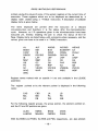
names given are those to be used in a *TABLE instruction.
AL
BESG*
CASP
DS(O)S
IB
MAP
OB
PG
SC
WAG
WBU
ALF
BM
CB
DS(15)S
LAP
MBP
OC
RAP
VS(Q)S
WAP
AS(O)S
BUS
CBSP
DS(63)S*
LBP
CA
OD
RBP
VS(15)S
WAU
AS(15)S
BUSSHIFT
CRSG*
DS(V)S
LRIP
CB
PAP
SA
VS(63)S*
WBG
AS(V)S
CA
CUALF
IA
LROP
OA
PBP
SB
VS(V)S
WBP
Register names marked with an asterisk (*) are only available in the LOUISE
assembler.
The register pointed at by the relevant pointer is displayed in the following
cases:
CAS
MA
RA
CBS
MB
RB
LA
PA
WA
LB
PB
WB
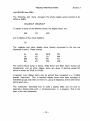
For the following register groups, the group pointer, the element pointed at,
and the S 1 and S2 pointers are given:
ALSG
LABPSG
BMSG
MSASG
BSSG
PMPSG
CSSG
PGSG
With the BSSG and PGSG, the BSS and PGS, respectively, are also printed;
- 18-
PSEUDO INS TRue nONS
Section 2
with MSASG also MSA.
The following two items represent the whole register group pointed at by
WAG orWBG;
WAGROUP WBGROUP
To obtain a dump of the different stores, the display items are:
MS
CS
WS
and to display all four local registers:
LR
The registers and other display items directly connected to the bus are
displayed in binary. These include:
AL
LA
MB
SB
AS
LB
PA
VS
BUS
LR
PB
WA
DS
MA
PG
WB
The Control Store dump is binary, Wide Store and Main Store dumps are
hexadecimal, and all other display items are given in decimal, except SC
which is written as TRUE or FALSE.
In general, more display items may be printed than requested in a *TABLE
pseudo instruction. This is because display items have been arranged in
indivisible groups and when one item in a group is displayed, all the other items
will be given also.
This subsection described how to build a display table, but not how to
associate a display table with a microinstruction in a program. That is the
topic of the next subsection.
- 19-
RIKKE-MATHILDA USER MANUAL
2.11 *OISPLAV or *0:
Format:
1. *DISPLAV.<no>
2. *DISPLAV.<no>: <Ioc 1>
3. *DISPLAV.<no>: <Ioc 1> - <Ioc 2>
<nO> may be either an integer (in the range [0,7]1 or one of the following
identifiers:
NONE
TRACE
STOP
Nothing will be displayed
Trace of Control Store locations is given
Simulation is stopped
The user should note the last item, because the simulators only have this
single STOP criterion, other than time limits inflicted by the operating systems
in the host computers.
Using Format 1 associates the display table numbered <no> with the
segment of microinstructions which follows it. The indicated display table will
be active until the next *DISPLAY instruction.
Using Formats 2 or 3 associates the display table with an instruction in
location <Ioc 1>, or instructions in the range <Ioc 1> through <Ioc 2>. The
simulators will assume that the user has created a table with the number
<no>, using a *TABLE instruction. If this is not the case, only a trace of the
Control Store locations will be displayed for those microinstructions affected
by the *DISPLAV instruction.
If no *DISPLAY instructions are given in a program, a trace of the locations
executed during the simulation will be given by default.
2.12 *ENTRV or *E:
Format:
*ENTRV = <constant>
where <constant> is an unsigned integer or a manifest.
- 20-
PSEUDO INS TRue nONS
Section 2
*ENTRY defines the address in Control Store at which execution will begin.
*ENTRY may be placed anywhere in the program. If *ENTRY is written
more than once, the last issued instruction will be used. A *ENTRY instruction
must always be given, if the microprogram contains the entry point for the
execution.
2.13 *VALUE or *V:
Format:
*VALUE
<list of value statements>
END
Each value statement in the list has one of two formats:
1. <name>: <Ioc 1> - <Ioc 2> = <value list>
2. <name>: <Ioc 1> = <value>
*VALUE allows the user to initialise register groups (or storage locations) prior
to execution. <name> is the name of the register group (storage) and the
interval <Ioc 1> - <Ioc 2> determines which elements of the group are
given values. The syntax for <value list> and <value> is given below.
(Note: the '{' and'}' brackets mean "0 or more occurrences of the bracketed
expression". 'ub' and 'Ib' mean "upper bound" and "lower bound", respectively.)
<value list> :: = <value> { ,<value> }
<value>
:: = <field descr> / <number>
<field descr> ::= [<field spec> { ,<field spec>}
<field spec>
<number>
(ub:lb)
:: =
1
= <number>
<signed integer or manifest>
The <field descr> type of <value> element is used when the user wishes to
initialise certain fields of a particular register (or memory location). The other
type is used when only a (right justified) value is to be inserted into the
- 21 -
RIKKE-MA THILDA USER MANUAL
register.
A few conventions should be observed:
1. When <value list> contains fewer <value> elements than are needed
to fill the number of registers indicated, the last element of the list will
be used repeatedly, as many times as necessary.
2. The indices <Ioc 1> and <Ioc 2> are always interpreted as unsigned
decimal integers, regardless of any *RADIX instruction.
3. The <integer> part of a <value> element is always read according
to the current base. There are certain restrictions on the format of the
field specifications:
a. The upper bound must be greater than or equal to the lower bound
and less than or equal to the width of the register group in question.
b. The lower bound must be greater than or equal to O.
c. If there is a sequence of field specifications, they must be written in
decreasing order and they must not overlap.
d. The upper and lower bounds must be specified as decimal integers
- manifest constants or constants written in another base are
disallowed.
4. It is often practical when working with the working registers WA and
WB to be able to indicate the group number and an index in that
group instead of giving the absolute location.
The register
identification for WA and WB may thus be followed by a
square-bracketed group number. Note it must be added between the
register name and the colon. The group number may be a manifest
constant.
5. Do not forget the terminating END.
Caution:
Although the bus masks can be initialised through a *VALUE statement,
this feature should be applied with great care, as it may
affect
all
following bus transports, including initialisations.
The following list indicates which register group names
<name> when using *VALUE to initialise the simulators.
- 22-
may replace
PSEUDO INSTRUCTIONS
ALSG
LA
PB
BESG*
LB
PGSG
BMP
LR
RA
BSSG
MA
RB
CAS
MB
WA
CBS
CR
MSASG PMPSG
WB
WAPS
Section 2
CSSG
PA
WBPS
Register groups marked with an asterisk (*) are only available on the LOUISE
assembler.
MS is an abbreviation of Main Store. The current version of the simulators
have a maximum of 256 words of Main Store which can be initialised with a
*VALUE statement.
Example:
*VALUE
WA
[4]
WB
END
4-10
100-255
[ (63:50) = 27, (49:0) = 50].
[ (63:50) = 2, (10:0) = 65]
2,3,10
2.14 *SNOOPER or *S:
Format:
1. *SNOOPER : <Snooper instruction>
2. *SNOOPER : <loC> = <Snooper instruction>
This instruction is only valid in the LOUISE assembler.
Format 1 associates the Snooper instruction with the microinstruction
immediately following it. No other pseudo instruction may be put between
the *SNOOPER instruction and its associated microinstruction. Format 2
associates the Snooper instruction with the microinstruction placed in location
<Ioc> of Control Store.
A detailed description of the operation of this pseudo instruction is given in
reference [9].
- 23-
RIKKE-MA THILDA USER MANUAL
3. THE SIMULATORS.
The RIKKE simulator functions in accordance with the description in [2[. The
MATHILDA simulator functions as described in [4] and [5]. It includes the
extensions (as compared to RIKKE) such as snoopers, status facilities and
interrupts. Only exceptions from the designed MATHILDA are the real time
clock and the external register - they are not simulated.
The physical configurations are not simulated either. The RIKKE simulator has
some simulated devices, whereas the MATHILDA simulator has none. The
simulated MATHILDA computer is in its stand-alone version, and the RIKKE
and MATHILDA simulators are totally independent and cannot interact.
This section contains a summary of the I/O connections in RIKKE-1 and
MATHILDA and how they are simulated.
RIKKE-1 and MATHILDA are equipped with ports, through which data to and
from external devices is transmitted. Each port has a data buffer which is
connected to the Main Data Path. A port buffer is read or loaded (depending
on whether the port is for input or output) using a bus transport operation.
Furthermore there is added a device selection mechanism which enables sixteen
devices to share one port. Each device has its own buffer and a device
selection register controls which device is connected to the port. A physical
device is plugged into a device buffer. Every device buffer has a flag bit which
is testable as a condition, and it informs on the status of the device buffer. On
input, the flag is set if there is data available in the buffer, and on output it is set
if there is space available, i.e. the device has consumed the contents of the
device buffer. The microoperations that control the transmission of data
between the port buffer and a device buffer are called activate operations. They
affect the device buffer flags as follows: An input activate operation resets the
flag indicating that data is no longer available; an output activate operation
resets the flag indicating that space is no longer available.
Finally each device buffer has an extra status bit called the mark bit. The mark
bit is designed to allow a device (on output) or the computer (on input) to
interpret the contents of the buffer as status information if the mark bit is on.
As an example of its use, see the paper tape reader connected to input device
- 24-
THE SIMULA TORS
Section 3
10 of port B on RIKKE-1 (section 3.2.1).
In the following we will describe the ports that exist on RIKKE-1 and
MATHILDA.
3.1 PORT A
Input and Output ports A are dedicated to Memory Input & Output and have
only one device buffer - i.e. there is no device selection on ports A. The
Memory is viewed as a device and is treated so. Thus an Input port A Activate
(lAA) microoperation initiates a read of one data word from Memory, and the
Input port A Data Available (lADA) condition indicates when the operation is
completed. The Output port A Activate (OAA) microoperation starts a write
into memory from the device buffer and the space available flag is set on
completion.
On RIKKE-1, Memory is called Main Store. The address of the location of
interest for an input or output operation is stored in the Main Store Address
register (MSA). This register is used by Main Store during the read or write
operation and the Main Store Address Busy (MSAB) condition indicates the
state of the register. If MSAB is set, Main Store is using MSA and the contents
of the register must not be changed. When Main Store is finished with the
address - this happens before the actual 1/0 operation is completed - Main
Store clears the MSAB condition.
The Memory connected to MATHILDA is named Wide Store and the
addressing of Memory in MATHILDA differs from the technique applied in
RIKKE-1. This is described in detail in section 3.3.3.
In the simulators the size of the simulated memory is 256 words.
3.2 PORT B
Input and Output ports B are the ports onto which all external devices are
connected. There is device selection on the ports and the selection is controlled
by Input and Output Device selection (lBD and OBD resp.) registers.
3.2.1 Input devices on the RIKKE simulator.
Device 0:
As described in [3] this device is special purpose. The contents
- 25-
RIKKE-MA THILDA USER MANUAL
of the· input buffer always forms a picture of the total data
available situation for all IB devices. Bit 0 has the same value as
the data available flag of device 0, bit 1 as the flag of device 1,
etc. The contents of the device buffer for device 0 can be
transferred directly onto the Main Data Path. Activation of this
device is therefore meaningless.
Device 1:
Is simulated as a character file. The activate operation IBA
causes the following:
1. Four hexadecimal digits are read from a character file, formed
into a 16-bit word (digit 1 into bits 15-12, digit 2 into bits
11-8, etc.) and placed in the device buffer.
2. One binary digit is read from the same file and placed in the
mark bit associated with the buffer.
All other characters that cannot be interpreted in this format are
skipped.
Device 8:
The buffer of the device forms a picture of the space-available
situation for all Output port B devices. Bit 0 is equivalent to the
space available flag of device 0 on OB, etc.
Device 10:
The paper tape reader is connected to the device and it is
simulated by an eight-bit binary file. An activation of the device
reads one frame (eight bits) into the eight least significant bits of
the device buffer. If the reader is empty (simulated by an
end-of-file mark) the mark bit of the device is set, and the
buffer contents are undefined. Otherwise the mark bit is zero and
the contents are valid.
Device
Device
Device
Device
12:
13:
14:
15:
Are used to read from with Wide Store. By default, Wide Store
is not connected to the RIKKE simulator, but may be so on
request. The interface between RIKKE-1 and Wide Store is
simulated as described in [8]. Reads from Wide Store to
RIKKE-1 are controlled by operations on Output port C and are
described in further detail in section 3.3.
An Input port B Activate (lBA) operation with Input B Device selector (IBD) out
of range (i.e. 2-7,9,11) will force the simulation to terminate. Similarly, if the
Input port B buffer (lB) is chosen as bus source in a micro instruction with IBD
- 26-
THE SIMULA TORS
Section 3
out of range, the result is undefined.
3.2.2 Input devices on the MATHILDA simulator.
Device 0:
Is simulated as a character file.
The activate operation IBA causes the following:
1. Sixteen hexadecimal digits are read from a character file,
formed into a 64-bit word (digit 1 into bits 63-60, digit 2 into
bits 59-56, etc.) and placed in the device buffer.
2. One binary digit is read from the same file and placed in the
mark bit associated with the device buffer.
All other characters that cannot be interpreted in this format are
skipped.
The setting of IBD has no effect in the MATHILDA simulator, i.e. regardless of
which device is actually selected using IBD - device 0 will always be referenced
when an activation or testing takes place.
3.2.3 Output devices on the RIKKE simulator.
Device 0:
Is dedicated to the loading of Control Store from the Main Data
Path. An Output port B Activate (DBA) operation loads the
Output port B port buffer into the device buffer which has been
renamed to the Control Store Data Buffer. The transfer will
always take place as the device space-available flag is set by
force.
Device 3:
The line printer for RIKKE-1 is connected to the device and is
simulated by a character file. An DBA operation transmits the
eight least significant bits of the port buffer to the character file.
Printable characters are those visible in the ASCII character set
(i.e. character value in the range 32-127) and the following
control characters:
action
car return
car return + 1 line feed
car return + 2 line feeds
top of form
- 27-
bit pattern
10000000
10000001
10000010
10001001
RIKKE-MA THILDA USER MANUAL
(observe that the most significant of the eight bits is set in the
control characters.)
All other values transmitted to the simulated printer have no
effect.
Device
Device
Device
Device
12:
13:
14:
15:
Are used to write into Wide Store. By default, Wide Store is not
connected to the simulator, but may be so on request (see
section 4.2.3). The interface between RIKKE-1 and Wide Store
is simulated as described in [8]. Writes to Wide Store are
controlled by operations on Output port C and are described in
further detail in section 3.3.
All other OBA operations with Output port B Device selector (OBD) out of
range (i.e. 1-2,5-11) produce a line on the default output file (see section
4.2.3) in the following format:
OB <OBD value> <contents of OB port buffer> <mark bit>
Example:
OB 71011 1111 0101 0011 1
3.2.4 Output devices on the MATHILDA simulator.
All output devices on MATHILDA except one are simulated by printing on the
default output file (see section 4.2.4) the equivalent information to that printed
on the RIKKE simulator: Port name, device number, data value and mark bit.
OB <OBD value> <contents of OB port buffer> <mark bit>
Device 4 is the exception and only functions differently when the Snooper
facility (see )E9A) is activated (see section 4.2.4). Device 4 is used to load the
Snooper facility from the Main Data Path. If the Snooper facility is not
activated, device 4 behaves as the other devices.
- 28-
THE SIMULA TORS
Section 3
3.3 PORT C
Port C only exists as an output port. The use of port C in RIKKE-1 differs
considerably from that in MATHILDA as will be seen.
3.3.1 Port C on the RIKKE simulator.
Devices 0 through 7 of Output port C on RIKKE-1 are reserved for control of
Wide Store, i.e. Output port C Device selector (OCD) is used to select a
Memory Address Port in Wide Store. The Store is not attached to the simulator
by default but this can happen on request (see section 4.2.3). The
interconnection between RIKKE-1 and Wide Store is simulated as described in
[8].
Device 0:
The contents of the device buffer is used as the address of a
word in Wide Store into which data is to be written. The
address is set up by an Output port C Activate (DCA) operation.
The data is taken from Output port B devices 12-15 and can be
written in one of two ways:
1. All four device buffers are activated with the mark bits
cleared. Then an entire 64-bit word, comprised of the
contents of DB device buffers 12-15, is written into Wide
Store.
2. One DB device buffer in the range 12-15 is activated with the
mark bit set. Then the contents of those device buffers which
have been activated are written into Wide Store and the
remaining 16-bit fields in the Wide Store word are left
untouched.
Device
1:
On the combined physical RIKKE-MATHILDA system, the
device is used to control the output from MATHILDA to Wide
Store. An DCA operation on the device causes the contents of
MATHILDA's Output port A device 0 buffer to be written into
Wide Store. The address in Wide Store is the contents of device
1's buffer.
In the RIKKE simulator MATHILDA's Output port A device 0 is
simulated by a character file (section 4.2.3). Thus an DCA reads
16 hexadecimal digits from the file, forms a 64-bit word (digit 1
into bits 63-60, digit 2 into bits 59-56, etc.) and enters it into
Wide Store at the address specified in the device buffer.
- 29-
RIKKE-MA THILDA USER MANUAL
Devicf;l 4:
The contents of the device buffer are used to address a word in
Wide Store from which data is to be read. The address is set up
by an OCA operation. The read is initiated by issuing a single
Input port Activate (lBA) operation with the device selector (lBD)
set to a value in the range 12-15. The resulting 64-bit word is
loaded simultaneously into the buffers of Input port B devices
12-15.
Device
On the combined physical RIKKE-MATHILDA system the device
is used to control the input to MATHILDA from Wide Store.
Similar to the write operation described under device 1, an OCA
on the device causes the data in the Wide Store word addressed
by the contents of the device buffer to be read into MATH I LDA' s
Input port A device buffer O.
In the RIKKE simulator, the contents of the Wide Store word are
written onto the default output file (see section 4.2.3), with an
indication of its intention for MATHILDA.
5:
Devices 2,3 and 6,7, although intended for Wide Store, are not used and in the
simulator operations on these devices have no definition.
Devices 8-15 are reserved for later purposes and have no interpretation in the
simulator.
3.3.2 Port C on the MATHILDA simulator.
Only device 0 of port C is defined on MATHILDA. All other devices are not
simulated.
Device 0:
Is dedicated to the loading of Control Store from the Main Data
Path. An OC: = BUS microoperation loads the port buffer from
the Main Data Path. The loading of Control Store from the OC
port buffer is enabled using the CSLOAD microoperation. The
transfer from the buffer to a Control Store location can always
take place, as no communication flags are necessary to control
the operation.
- 30-
THE SIMULA TORS
Section 3
3.3.3 Wide Store Addressing in MATHILDA.
Wide Store is a sharable device and has eight Data Ports (numbered 1 to 7).
Each port has its own address buffer and all address buffers can be referenced
by the connected processors. MATHILDA has one Wide Store Address register
(WSA) and a Wide Store Port selector (WSP) to indicate which address buffer
is to receive the address. A Wide Store Address Activate (WSAA)
microoperation transfers the contents of WSA into the selected address buffer
of Wide Store. The Wide Store Space Available condition (WSSA) indicates
whether the selected address buffer is ready for a new address. Each port in
Wide Store has one dedicated function and port 1 and 5 are used for
MATHILDA Read and Write operations. A Read operation for MATHILDA thus
requires the setting of Memory address buffer 1 in addition to an Input Port A
Activate operation.
- 31 -
RIKKE-MA THILDA USER MANUAL
4. USING THE SYSTEMS.
The simulation systems described in this section are those available on the
DECsystem 10 belonging to the Department of Computer Science at Aarhus
University. Thus the information included is machine dependent and does not
generally apply to systems running on other computers.
4.1 Conventions.
On the PDP-10 a named file is identified by a filename and a file extension.
<filename> .<extension>
Source programs are processed by compilers, assemblers etc. as implied by the
extension - if it is recognisable. (E.g. the extension ALG indicates that the file
is an Algol source text.) This convention has been adopted for the simulation
systems.
A source file for assembly must have the extension MIA for the MARIA
assembler and LUI for LOUISE. The assemblers generate files with the filename
taken from the original source file and extensions that describe their purpose.
<name>.MIA (or LUI)
<name>.RIS
<name>.MAS
<name>.LPT
<name>.PTP
source text
interface file for RIKKE
interface file for MATHILDA
program listing
object code file
Similarly, the simulators accept only files with the proper extension (i.e. RIS
and MAS, respectively) for simulation and create output files with appropriate
extensions. Details on this are given in section 4.2.3.
The assemblers and simulators are initiated by a call in the format
RUN <program name> ( <parameter list> )
where <program name> is:
- 32-
USING THE SYSTEMS
MARIA[114.114].
LOUISE[117.117j.
Section 4
RIKKE[114.114]
MATHILDA[117.117]
<parameter list> must contain as first element the filename (without extension)
of the file on which the program is to operate. Following it the user may list the
options he feels like activating in the assembler or the simulator. Entries in the
parameter list are separated by spaces. The sections after this one list available
options for the systems.
The assemblers can generate output either to the simulators or for the
computers. Output for simulation is an interface file that the simulator reads
and uses for initialisation - it contains storage and register images and control
information for the display facilities. Output for the computers is a file formatted
to suit the various loaders available on the machines (see references [6] and
[7]). The file may be punched without further processing onto paper tape.
*VALUE statements are used to initialise registers prior to execution of a micro
program. Output of this sort causes no trouble when it is for simulation.
whereas it adds some extra complexity when the micro program is to execute
on the computer itself. Initialisation is accomplished by preceding the actual
micro code with small sub-routines that handle the register setup before the
code is loaded into Control Store.
-33-
RIKKE-MA THILDA USER MANUAL
4.2 S\Jmmary of options.
In the parameter list passed to an assembler or a simulator certain options can
be specified. They are listed in the following sub-sections. The filename of the
source file (without extension) is always indicated by the metasymbol <name>.
4.2.1 Options in the MARIA assembler.
SC
object code is passed to the RIKKE simulator via the simulator
interface file called <name>.RIS.
OC
object code is formatted on a file to suit RIKKE-1's Bootstrap
Loader and is named <name>.PTP. The file is ready to be
punched without further processing.
MARIA operates with the OC option on by default.
D
object code is formatted on a file to suit RIKKE-1's Deadstart
Loader and is named <name>.PTP. The file can be punched
immediately. No *VALUE statements are allowed in the micro
program if the D option is applied.
x
on the micro program listing all Control Store addresses are
printed in hexadecimal notation. This is practical if the program
execution is checked on the physical machine because it is
equipped with hexadecimal displays of the current Control Store
address.
LR
all labels and manifest constants are listed together with their
associated values.
MS <loC>
The option permits micro program overlays to be loaded into
Main Store by the Bootstrap Loader at program load time.
The micro program is loaded into Main Store as follows:
Let n denote the number of Control Store words comprising the
micro program overlay. Then the integer (n-1) is entered into
Main Store location <loC>. Starting at location <loC> + 1, the
micro program image is entered, with each Control Store word
occupying 4 consecutive Main Store words: Bits 15-0 in word 1,
bits 31-16 in word 2, bits 47-32 in word 3 and bits 63-48 in
word 4.
Only one *ORIGIN pseudo instruction is allowed in a micro
program if the MS option is applied.
- 34-
USING THE SYSTEMS
TTY
Section 4
the option indicates that source text input is to be taken from the
user's teletype. The micro program listing is suppressed and the
simulator interface file (or the punch file) is given the filename
"TTY".
- 35-
RIKKE-MATHILDA USER MANUAL
4.2.2 Options in the LOUISE assembler.
SC
object code is passed to the MATHILDA simulator via the
simulator interface file called <name>.MAS.
OC
object code is formatted on a file to suit MATHILDA's Bootstrap
Loader and is named <name>.PTP. The file is ready to be
punched without further processing. LOUISE operates with the
OC option on by default.
D
object code is formatted on a file to suit MATHILDA's Deadstart
Loader and is named <name>.PTP. The file can be punched
immediately. No *VALUE statements are allowed in the micro
program if the D option is applied.
x
on the micro program listing all Control Store addresses are
printed in hexadecimal notation. This is practical if the program
execution is checked on the physical machine because it is
equipped with hexadecimal displays of the current Control Store
address.
LR
all labels and manifest constants are listed together with their
associated values.
TTY
the option indicates that source text input is to be taken from the
user's teletype. The micro program listing is suppressed and the
simulator interface file (or the punch file) is given the filename
"TTY".
- 36-
USING THE SYSTEMS
Section 4
4.2.3 Options in the RIKKE simulator.
KA
simulates the external condition switch KA. By default, the
condition is false. Applying the option sets the KA condition
true.
KB
simulates the external condition switch KB. By default, the
condition is false. Applying the option sets the KB condition to
true.
PTR
connects the paper tape reader to the simulator on Input port B
device 10. The paper tape reader is simulated by a character file
named < name>. PTR. It is the user's responsibility to create such
a file.
LP
connects the line printer to the simulator on to Output port B
device 3. Any output from a micro program to this device is
written on a file called <name>.LP.
IB
connects a character file named <name>.1 B to Input port B
device 1. It is the user's responsibility to create the file in the
format described in section 3.2.1.
OB
output to device numbers on Output port B not simulated (i.e.
1-2,5-11) is printed on the file named <name>.OB. If the option
is omitted, this kind of output is typed on the user's teletype.
WS
attaches the simulated Wide Store, 256 64-bit words, to the
simulator.
MOA
attaches the simulated Output port A of MATHILDA to the
simulator, which is a character file called <name> .MOA in the
format described in sectiqn 3.3.1. An activation of Output port C
device 1 on the simulator causes a read from the file into the
simulated Wide Store. The user is responsible for creating the
MOA file.
TTY
trace output from the simulator is typed on the user's teletype.
By default the simulator prints trace output on a file called
<name>.TRC.
- 37-
RIKKE-MA THILDA USER MANUAL
4.2.4 Options in the MATHILDA simulator.
KA
simulates the external condition switch KA. By default, the
condition is false. Applying the option sets the KA condition
true.
KB
simulates the external condition switch KB. By default, the
condition is false. Applying the option sets the KB condition to
true.
IB
connects a character file named <name> .IB to Input port B
device O. It is the user's responsibility to create the file in the
format described in section 3.2.2.
OB
output to device numbers on Output port B not simulated (i.e.
1-15) is printed on the file named <name>.OB. If the option is
omitted, this kind of output is typed on the user's teletype.
TTY
trace output from the simulator is typed on the user's teletype.
By default the simulator prints trace output on a file called
<name>.TRC.
SNOOP
All Snooper facilities are activated in the simulator. For a further
dicussion of the operation of these facilities we refer to reference
[9].
- 38-
USING THE SYSTEMS
Section 4
4.3 Examples of command sequences.
This section gives a couple of examples of the control statements to the
Operating System necessary to run an assembler-simulator system.
Example 1.
Assume that
1. the micro program resides on a file named PRG.LUI,
2. it uses Input port B device 0,
3. it is to be simulated.
Then the following control statements are required:
RUN LOUISE[117,117) (PRG SC)
RUN MATHILDA[117,117) (PRG IB)
Example 2.
Assume that
1. the micro program resides on a file named TEST. MIA,
2. it is to run on the physical RIKKE-1,
3. it is to be loaded by the Deadstart Loader.
Then the following control statements are necessary:
RUN MARIA[114,114) (TEST X D)
PUNCH TEST
4.4 Programming and simulation examples.
Two examples are given in the following. The first example is the MATHILDA
Deadstart Loader. The assembler listing is followed by the simulation output,
which illustrates the display facilities of the assembler/simulator system.
The second example is the RIKKE-1 Bootstrap Loader. We have abstained
from giving displays of a simulation of this program as these would be very
extensive.
- 39-
RIKKE-MA THILDA USER MANUAL
Exall1ple 1
MATHILDA Deadstart Loader.
The source resides on file bootno.LUI.
The Assembler output (file bootno. LPT) contains the foilowing:
LOUISE VERSION 1.2 PUP-tO
LINENU
0:
cs
7 DECEMBER 1971
14:52:41
ADDRt:SS
" . . . . . . . . . . . . . . . . . . . . . . . . . . . . . . . ,"' •••••••••••••••••• , ••••••
**, ••• ** •••••••••••••••••••••••••••••
10
"
3,
• aOOTSTRAPLOADER AND NORMALIZER fOR MATHILDA
• AT EXIT \liE HAVE
"""
MAlO]
= LA(O] =
MAlll
PAll]
=
L8[OJ
:;: pIHO]
= PAlO] =
NCJo'ASK
:;: FULLMASK
MAP = LAP:;: PAP = PBP = 0
LRp
0
BSoS = PGS
eM
RAP = RBP
0
flAP AND WBP ARE UNCOUPLED
SCUALF IS SET TO AtB
"
=
""10
II
12
=
=
14
KC AND KD ARE CLEARED
DB IS ACTIVATEO
15
10
OA IS CLEARED
HI IS ACTIVATED
13
17
18
,.
19
*T.1
"
""
MA
END
*T.2
BUS.SA.eli
END
"
"
""
25
27
30
31
,
"3334
ALLIS:
35
3.
MA:=ALL1:;;
.ilL;
MA:=AL:
37
""
""
40
41
....
,
•
5
7
AL:
ALI
AL:
10
,
4S
11
AL;
47
12
13
14
15
48
49
50
51
ALF:=
9
toO.TRACE
READ:
:
AS:=AL.<II>:
LR:=lB:
,
CB:=SI>.
RB!.
RA!.
CI>·I.
I1I:!PC.
ALLOS.
PAPe.
L8pe
MAPe.
PA:=IWS,LAPC
LB:=5B,SCUALf+.LA:=SB
RAPC,
PB:=BUS.PAP+I
HA!.
PA:=IlUS """""
SA:=SB. RA!
IIA!,
PGS:=(M """"~
OC:=BUS.
KDC
CSLeAD
OAP
SAtl
I<CC.
SA:=SB,
ALf:=
ALLOS.
PAPC.
MAPC
BSS:=Cl>'.CAtl.
ALf:=
A!li:l.
""
IR-RtAD
:II-READ
:SA
:P·RIcAD
:UNLE.SS C\:l THE'" IUl
ISA
CA:=9733
ItlA.
LRPC.
'IIBPUNCCUPLE
'IIAPUNCllUPLE
*D.STOP:lb-I023
PkOGRAM CORIlECT
- 40-
:R+2
:H 0(3) 1l-lEr. RAtl "LSE HlFlc-l
:11' lE'DA TIHN HERE-I HSr H"k~
USING THE SYSTEMS
Section 4
Example 1 continued.
MATHILDA Deadstart Loader Simulation Output.
The simulation output resides on file bootno.TRC.
Note: In order to use input to the microprogram, option IB has to be given to
the MATHILDA simulator.
MATHILDA SIMULATOR
••• ++++++ ....
7 DECEMBER 1971
14;SlI4:l
+++ •••••••• +++++++++.+++++++++++ •••• ++++++ •• +++.++++++++++++++ •• +++++ ••• ++++++++++++u+++++++ •• ++++
E.IEr;:U'JIN(: lN$1RUcnOH AT.
AD"~~SS
0
++++ •• ++++ ••• +++++ ••••••• ++.+++++++++ ••• ++++++++++ •••• ++++++H'.++++++ ••• ++++++ ••• +.++ ... +•••••• +++t+++++++ •• ++.+
STATUS OF MATHUDA SIMULATOR:
MAP: 0
MM 11111111 11111111 11111111 11111111 11111111 11111111 11111111 11111111
MBP: 0
MB: 00000000 00000000 00000000 00000000 OODOOOOO 00000000 00000000 00000000
8M: 11111111 11111111 11111111 11111111 11111111 11111111 11111111 11111111
.+++++++++.+++++++++ •• ++++++++.+++++++++++*++++++++++++++++++++++.+++++++ ••• +++++ •••• +++++++++++++++++++++++++
EX8:('I,J'J'IN~.
JNs'J'(l,UCTIOH AT
~I;)I;)R~$$
1
++ •• +++++.++.++ •• ++++.t •• t+ •••• ++.t •• +++ •••• +++++++.++++++++++++++++ •• +.+++++++.+++++.++++.++++.+++++.++++++++
atA'l'US OF MATHILDA SIMULATOR I
MAP;
0
Milo: 11111111 11111111 11111111 11111111 11111111 11111111 11111111 11111111
M8P;
0
M81 00000000 00000000 00000000 00000000 00000000 00000000 00001)000 00000000
8Mz 11111111 11111111 11111111 11111111 11111111 11111111 11111111 11111111
++ ....... +++.++++++++++++++++++++++++++++++++++++++++.++++++++++++++++++++++++++++++++++++++++++++++++++.++++++++
EXECUTING.
J~$1RUCTION
AT
~DDREsS
2
++.++t+++++t++t+tt.+++t++tt++t++++++t++.++ •• ++++++ •• ++++++++++++++.+++++++++ •• +.+++ ••• +++++ ••• +++ •• +••••••••• +
STATUS OF MATHILDA SIMUl.ATOR:
MAP;
0
Milo; 11111111 11111111 11111111 11111111 11111111 11111111 11111111 11111111
MBP:
0
MBI 00000000 00000000 00000000 00000000 OOOQOOOO 00000000 00000000 00000000
8Mz 11111111 11111111 11111111 11111111 11111111 11111111 11111111 11111111
••• ++++++++++.+ •• ++++++++++.++++++++++++++.+++ •• +•• +•• +.++.+.+++++.++.++++++++++.++ •••••• +•• t+t+++ •• ++++++ •• ++
EXECUTING INSTRUCTION AT AI;)DRtSS j
+++++++++++++++++++++++.+++++t++++.+++ ••• +.++ •• +••• ++++ •• ++++ ••• ++++++++++ •• +++.+ •• +.++.++.+.+ •••••• t+ •••• +++.
STATUS OF MATHIl.DA SIMULATOR:
MAP:
1
Milo: 00000000 00000000 00000000 00000000 00000000 00000000 00000000 00000000
0
Mti: 00000000 00000000 00000000 00000000 00000000 00000000 00000000 00000000
8M: 00000000 00000000 00000000 00000000 00000000 00000000 00000000 00000000
M8P:
++++++++++++++++++++++.++++++++ ••••• +++++++ •• ++.+.++.++ •• ++++++++++t+++ •• ++.+ •••••••••• +.+ ••• +.+ •• +••••••• +••••
EXECUTING INSTRUCTION AT ADDRESS 4
+•• ++++++++++ •••• +••• +••• +•• +++.++++++ ••• +.+ •••• +++.++ ••• ++.++.+.++.+ •• +•••••••••••••••••••••••••••••••••••• ++
STATUS Of MATHILDA
SIMULATO~:
MAPI
1
MA: 00000000 00000000 00000000 00000000 00000000 00000000 00000000 00000000
MBP:
0
MB: 00000000 00000000 00000000 0000.0000 00000000 00000000 00000000 00000000
8M: 00000000 00000000 00000000 00000000 00000000 00000000 00000000 00000000
•• +++++++++++++++++.+++++++++++++++++++++++ ••• +.+++.+.+++++++++++++++++++.++++++++++.+ •• +++++ •• +++.++ ••••••••
-->12
·">13
-">15
..... >14
.... >13
-->15
-->14
-->lJ
-">15
-">14
-->lj
-">15
-->14
•••• +•• +••• +.+ •• +•• ++ •• ++++++++++++ ••••• ++++.++.+++++++++++++++++.+++++.++++++++++++++++++++++++++++ •• ++++.++.
EXECUTING lNS,RoCTION AT. ADDRUS 5
••••+.++++++.++.+.++++++++++++++++.++t+++.t++++++++++++++++++++++++++++++++++++.++++++.++++++.+++.++++.++++++
aTAlUS OF MATHILDA SUIULATORI
CAl 9737
SAl
C81
12
8US: 00000000 00000000 00000000 00000000 00000000 00000000 00000000 001000~0
- 41 -
RIKKE-MA THILDA USER MANUAL
Example 1 continued .
••••••••• ++++++.+++ ••• ++ ...
--)12
"-)13
.... >15
++ ••• +++++.+++.++
••• ++.+++ •• ++.++++++++++++++++.+.+++ •• ++++++++++++++ ••••-++.++ •• ++ ..
.... )11
.... >15
-">14
"->13
.... )15
--)14
-->ll
.... >15
..... )14
..->U.
.
.
• i'++++++++t+.+.+.++++++++++.+++++++++++.+.+.+•• ++++++++ ... t+t+++++.+.+++++.+++++ ••• ++i;++.+++++.++++++++++++++"
EXECUl'lNG J{t'l'~UCTJON AT. ~Dl»~~$S 6
••••• ++++ ••••• ++ ••• ++++++++++++++.+.+.+++++.+++ ••• +.++ •• t
.
. . . . . . . . . . . . . . . . . . . . . . . . . . . . . . . . . . . . . . . . . . . . . . . . . . ...
SrATU& OF MATHILDA SlMuLutnu
SAl
12
BUll 00000000 00000000 00000000 00000000 00000000 00000009 00000000 00000000
++ •••••••
+++++t ••• +++++ •••••• +++.++.+++.· ..................... t ...............................................
-->15
-->14
-->13
-->15
-->14
-->13
-->15
-->14
-->.1]
-->15
++.+++ ••••••
-->12
-->13
..... . .....
'. ....
.
...........................................................................................................................
.
-~>..
EIE(I,I'JIIG. J''''I,ICIID" A'J' ~tlQtlE"$ 7 .
.
.
.........................................................................................................................+
lTA'IU&
or
MA'IHILDA 8IMULA'lOR i
CII
CA. 9137
IAa
32
auai llt.lt.ll1 00000000 10101010 10101010 "Q001000l 00010001 00100010 00100010
..................., ....+++.++ ...... +++............+1' •• +....++..........+.......................................+..... \
""\I'tJN~. JIJI''''VCTJDIJI A'I.
"'tI{)"" •
... . ..
...
.
.
......................................................................... .v................................................................. .
l'IA'I'U8 QI' MA"THILO" SIMULAtOR'
CAi 97,)1
aAI
luai
• cal
12
00000000 00000000 00000000 00000000 00000000 00000000 00010000 00000000
.......+••••+••+..................++..................+........ ++.......+..................................................++ ........
'~'TI~. ,,""~n~'. AT .•~~'''' •
...
...
. ...
....
.
...............................................................................................................+..............
81'ATU8
ur
MATrill.ol.lA tUMUI.ATUIt I
CAl 97J7
aAI
Ctll
J2
IIUII 001100000 00000000 00000000 00000000 00000000 00000000 1011100000000000
.................................................................................................................
-·>12
··>lJ
··>1!:i
··>14
··)13
-->15
-->14
··>13
-->1~
·.>14
··>13
··>111
-·>14
.......................
+••••••••••••••••••••• +.+++ •••••••••••••••••••••••••••••••••••••••••••••••••••••••••••••
UEtUflNG INaTItUC'UUN AT lDOflESS 10
•••••••••••••••••••••••••••••••••••••••••••• +.+ .... t.tt •••••••••••••••••••••••••••••••••••••••••••••••••••••••
81'ATUI
or
MATHILDA
CAl 9137
IIMU"A'IO~
I
C81b55J~
.u
IAI
BU81 00000000 00000000 00000000 00000000 00000000 00000000 00011010 00000000
. . . . . . . . . . . . . . . . . . . . . . . . . . . . . . . . . . . . . . . . . . . . . . . . . . . . . . . . . t •••••••••••••••••••••••••••••••••••••••••••••••••••••••
I:Xt:CI,lTlNG INSTR\lCTlOH AT AD!;!It!::SS 11
...................................................................................+•••••••••••••••••••••••• +•••
STATUS
or
MATHILDA SIMULA1'OIlI
CAl 9737
SAl
C1I165$35
.12
8USI 00000000 00000000 00000000 00000000 00000000 00000000 00000000 00100000
.....++ ••••+... +•••••••••••••••••• +..............................+•••••••••••••••••••••••••••••••••••••••••••••••
....+..... +•• ++ ••••••••••••••••• +.............................+•••••••••••••••••••••••••••• +•••••••••••••••••••••
EXECUtIUN STOPPED AT ADDRESS I
32
- 42-
USING THE SYSTEMS
Section 4
Example 1 continued.
Input to bootno.
Note: Input port B (lB) takes its data from the file bootno.IB which contains the
following:
0000
0000
0000
0000
0000
0000
0000
0000
0000
0000
0000
0000
0000
0000
0000
0000
0000
0000
0000
0000
0000
0000
0000
0000
0000
0000
0000
0000
0000
0000
0000
0000
0000 0000
nooo 0000
0000 0000
0000 0020
0000 0000
0000 0000
0000 0000
0000 0000
0000 FFOO
0000 AAAA
0000 1111
0000 2222
0000 0000
0000 0000
0000 0000
0000 0020
0
0
0
0
0
0
0
0
0
0
0
0
0
0
0
0
-43-
RIKKE-MATHILDA USER MANUAL
Example 2
RIKKE Bootstrap Loader.
MAMIA VE~.sIUN i.l. PDP"HI
~~NENO
CS
7 U~CHtlt"1< 1917
14:55: 9
AOO}l:E~~ ••••••••••••• , . . . . . . . . . . . . . . . . . . . . . . . . . . . ,
•• , . . . . . . . . . . . . . . . . . . . . . . . . . . . . . . . . . . . . . . . . . . . . . . . .
l:
"
.,"
".,"
3,
TH1::: LOADEP CAN I<t:AD IHNAio~ TArEt> fRON A B BIT PAPERtApEREADUI
INTO CUNTflOL.sTOPE "ftC MAINS1CFt: AND WIDE STOFIE
....................." ........................................................................
5,
NONSEftSE TO BE PUT
10;
11:
12;
..
..,
13'
141
15:
ASO
PTit
11,
."."
,.,
=
II
2
10
...............................................................................................
26:
..
..•••
•••,
'"
3., •••
'"
3"
"5
,
'6,
27:
*ORG=461
LOADER;
."
42'
431
44:
• 51
46:
47:
o
,:
H!D;=
LOOPz
PTR,
LFlP C.
ALLOS.
OAR,
SCUALF+
PA;=BUS
IIA!.
OSDC
."
47 •
EXI::CUTEz
NXT;
os;
IIA!.
:If' BUS THEN Ii-LOADER
,R-SUMIIUD
JIf' DSIl5)
uf' D3(14)
:IF' Ds(12)
:IF' DS(1]]
4b6
410
471
472
IBA
;It· UIDA THI::H HEIIE+1 ELSI:: H[Pi:
IS,
AU';.
AS.MA; .. AL;
•• 3
3.,
ALL05
""'ENTRY=461
all
24:
25:
311
18:
39:
401
CELL 0
ALF:e
END
'"
'"
]2:
331
l4:
351
uno
PBI
SA;=SB
:1I .. sUMCHEClt
:SA 0
:R ... LOAOEII+l
IIA!
,R-SUMCHECK
THEN
THEN
THEN
THFN
R-C3LOAU
II-MSLOAD
II.-WSLOAD
HEIIE+1 ELSE II-LOOP
...............................................................................................
..
"~-LOAD£R+l
-44-
USING THE SYSTEMS
Section 4
Example 2 continued.
MARlA VERSION 4.J. ftlP-IO
...
lolNENO CS ADDRUS
48:
50:
51:
52:
5J.
54:
•••
56.
57:
58.
7 DECEl!8ER 1911
14:55:13
I
••••••••••••••••••••••••••••••••• , ••••••••••••••••••••••••••••••••••••••••••••••••••••••••••••••
·
... ...............................................................................................
·
.
".
.,.
'"
".
".
MSf.,IlAD:
DSI
DS.
L2:
L"
ou.os;
0 ..
;R-SUllilEAD
MSA;=!B,
CA:-=SB.
RAt
M8A-l
OAA.
IIA!
MSA+l.
:R-SUMJlEAD
;fl-Ll
JIF CA THEN It-NX'I Hat" HEREtt
JR-SUMIIEAD
,.F OASA THEN II:-L2 ELSE HERE
,.
,,
...... .,..,.48'...
,
,
•••
••• ."
......
................................................................................................
...
.g.
'"
'" ... ...
v.
,'50.. ...
,
,,'".... ••...•••• 0"
.
................................................................................................
.......•••" ..."...•••,
,..
•••
...... .., ................................................................................................
...." ..•••••••••,, ,,
."
... ."•••
,
.............................
...............................,..,.............,..................
59:
•••
."
.. 1
CSI.OAD:
.83
LL:
loLL:
DS •
os:
Oer·D5,
IIA1.
CLC.
Ch=SB.
CHI=
,R"'SU/IIRt;AD
PAl
DBA.
,SA
CSLCAO
ur C8 THEN HERE+l ELSE R-LLL
:IF ell THEN HEflE+1 ELSE R"LL
CB-l
CA-l
66:
67:
,R-Nl'I
488
10:
,ilAI.
!fSLOAD:
72:
H.
'92
VS: .. OS
DS
,IIAI
,CA;_S8.
081_05
,CB-l.
.!=B,_SG.
'DCA.
V&:=AL
W]:
LR:"VS
:
08DC.
IXDC
LRP-l.
DBA.
C8S,_C8
LRP .. t
DCI_BUS
OBDe.
OBO-l.
CA"l
RAI
,R-SUJIIIRUO
;R"'SUMR[lO
;It-W]
IIF ~B 'IHEN KEllh1 ELSt: It-Ilill
;IF OCSA 1HlN HEIIE+l ELSE HERE
;IF CA 'IHEN it-NIT ELSE HEME+!
;It-S!JMitEAO
,IF OBSA 'IHEN M-1ii2 ELSE HERE
SEtALF +1
BO.
II.
$UMRIE"OI
IS:
87.
I
U(lS)SI:I
LRI_IB.>8,LIIIP+I.
LIII:lAL,
ABI_18;
LRIP-l.
DS.A&I=AL,
AS,_AL,
0\80.
: IF 18DA THEN HERE+l ELSE HE'RE
LRPC
SETALF 8. AS>.
lO •
" ' IBDA THEN MEill;..1 ELSE" HERE
SIETALF + •
LRP+l
LRP-l
litA+1
01.
91.
SUMCMECKt :
DSI_AL,
.tI
LRI_D8;
ALFI-=
ALL08.
05(011)5:·1.
SEtALF
UIP-l
LII,_AL, " LIIIP+I.
ASlaoa,
ALl: ..
'96:
5O
99:
100;
1011
51.
A8:_"L;
AL':=
LRPC
+•
DI<
,R+8UMRUD
RA!
A EOV B,
LRP-l
ALLOS.
LRP+l
IIF AI. THEN HERE+! ELSE R+2
JRA+!
,IF KA THEN It-LOADER ELSE HElIE
~
PROGRAM CORRECT
- 45-
RIKKE-MA THILDA USER MANUAL
tList 9f References.
1. M. Richards: The BCPL Reference Manual.
Technical Memorandum No.69/1-2,The Computer Laboratory,
.
Corn Exchange Street, Cambridge, England.
2. J. Staunstrup: "A Description of the RIKKE-1 System".
DAIMI PB-29, May 1974.
3. E. Kressel, J. Staunstrup: "The RIKKE-1 Reference Manual".
DAIMI MD-7, April 1974.
4. P. Kornerup, B. Shriver: "A Description of the MATHILDA Processor".
qAIMI PB-52, September 1975.
5. P. Kornerup, B. Shriver: "An Overview of the MATHILDA System".
DAIMI PB-34, August 1974.
6. B. Stroustrup: "Bootstraploader".
(DAIMI internal document), January 1974.
7. O. Sorensen: "ROM-Deadstart".
(DAIMI internal document), January 1974.
8. P. Kornerup: "The Wide Store on the RIKKE/MATHILDA System".
(DAIMI internal document), January 1973.
9. I.H. Sorensen: "A Description of the Snooper Facility for the extended
RIKKE System".
(DAIMI internal document), June 1974.
- 46-
Micro
Archives
5-6
S~rensen,
Ib Holm.
RIKKE-MATHILDA microassemblers and simulators on the DECSystem-10 / by Ib Holm
S~rensen and Eric Kressel.-- Aarhus, Denmark: Datalogisk Afdeling, Mathematisk Institut, Aarhus Universitet, 1977.
(DAIMI; MD-28)
I. Joint auth
or.
II. Title.