1
LP0631
CRIMSON 2
USER MANUAL
MODULAR CONTROLLER
Re-Order from
OmegamationTM
1-888-55-66342
1-888-55-OMEGA
omegamation.com
Copyright © 2003-2006 Red Lion Controls.
All Rights Reserved Worldwide.
The information contained herein is provided in good faith, but is subject to change without
notice. It is supplied with no warranty whatsoever, and does not represent a commitment on
the part of Red Lion Controls. Companies, names and data used as examples herein are
fictitious unless otherwise stated. No part of this document may be reproduced or transmitted
in any form or by any means, electronic or mechanical, without the express written
permission of Red Lion Controls.
All trademarks are acknowledged as the property of their respective owners.
Written by Mike Granby and Jesse Benefiel.
GETTING STARTED
TABLE OF CONTENTS
TABLE OF CONTENTS
GETTING STARTED ........................................................................................... 1
SYSTEM REQUIREMENTS ..................................................................................... 1
INSTALLING THE SOFTWARE................................................................................. 1
CHECKING FOR UPDATES ..................................................................................... 1
INSTALLING THE USB DRIVERS ............................................................................ 2
QUICK START .................................................................................................. 3
OVERVIEW ...................................................................................................... 3
MODULES........................................................................................................ 3
COMMUNICATIONS ............................................................................................ 4
MAPPING DATA ................................................................................................ 4
DOWNLOADING ................................................................................................ 7
CONNECT THE TWO ........................................................................................... 8
CRIMSON BASICS ............................................................................................. 9
MAIN SCREEN ICONS ......................................................................................... 9
MODULES .......................................................................................................................................9
COMMUNICATIONS ............................................................................................................................9
DATA TAGS ................................................................................................................................... 10
USER INTERFACE ............................................................................................................................ 10
PROGRAMMING .............................................................................................................................. 10
DATA LOGGER ...............................................................................................................................10
WEB SERVER ................................................................................................................................. 10
SECURITY MANAGER ....................................................................................................................... 11
SELECTING THE MODULAR CONTROLLER ............................................................... 11
USING BALLOON HELP ...................................................................................... 12
WORKING WITH DATABASES .............................................................................. 12
DOWNLOADING TO THE MASTER ......................................................................... 12
CONFIGURING THE LINK ................................................................................................................... 12
VERIFYING THE USB LINK ................................................................................................................ 13
SETTING THE IP ADDRESS ................................................................................................................ 13
SENDING THE DATABASE .................................................................................................................. 13
EXTRACTING DATABASES .................................................................................................................. 14
MOUNTING THE COMPACTFLASH ........................................................................................................ 14
FORMATTING THE COMPACTFLASH ...................................................................................................... 15
SENDING THE TIME AND DATE ........................................................................................................... 16
UPDATING VIA COMPACTFLASH ........................................................................... 16
MODULE CONFIGURATION ............................................................................... 17
WORKING WITH MODULES ................................................................................ 17
INSERTING MODULES ...................................................................................................................... 17
MOVING MODULES ......................................................................................................................... 17
EDITING MODULES ......................................................................................................................... 17
CSPID – PID MODULE PROGRAMMING ................................................................ 18
THE GENERAL TAB .......................................................................................................................... 18
THE CONTROL TAB ......................................................................................................................... 20
REVISION 6
PAGE I
TABLE OF CONTENTS
CRIMSON USER MANUAL - MODULAR CONTROLLER
THE POWER TAB ............................................................................................................................ 22
THE ALARMS TAB ........................................................................................................................... 23
THE OUTPUTS TAB ......................................................................................................................... 26
AUTO-TUNING ...............................................................................................................................27
AVAILABLE DATA ............................................................................................................................ 30
CSSG – STRAIN GAGE INPUT PID MODULE PROGRAMMING....................................... 34
THE GENERAL TAB .......................................................................................................................... 34
THE CONTROL TAB ......................................................................................................................... 36
THE POWER TAB ............................................................................................................................ 38
THE ALARMS TAB ........................................................................................................................... 40
THE OUTPUTS TAB ......................................................................................................................... 42
AUTO-TUNING ...............................................................................................................................43
AVAILABLE DATA ............................................................................................................................ 46
CSTC/CSRTD – TEMPERATURE INPUT MODULE PROGRAMMING ................................. 51
THE CONFIGURATION TAB ................................................................................................................ 51
AVAILABLE DATA ............................................................................................................................ 52
CSINI/CSINV – ANALOG INPUT MODULE PROGRAMMING ......................................... 53
THE CONFIGURATION TAB ................................................................................................................ 53
THE LINEARIZATION TAB.................................................................................................................. 54
AVAILABLE DATA ............................................................................................................................ 55
CSOUT – ANALOG OUTPUT MODULE PROGRAMMING ............................................... 56
THE CONFIGURATION TAB ................................................................................................................ 56
THE INITIAL OUTPUT TAB ................................................................................................................ 57
AVAILABLE DATA ............................................................................................................................ 58
CSDIO – DIGITAL I/O MODULE PROGRAMMING ..................................................... 60
THE CONFIGURATION TAB ................................................................................................................ 60
THE LOGIC EDITOR TAB................................................................................................................... 60
AVAILABLE DATA ............................................................................................................................ 62
CONFIGURING COMMUNICATIONS..................................................................... 65
SERIAL PORT USAGE ........................................................................................ 65
SELECTING A PROTOCOL ................................................................................... 65
PROTOCOL OPTIONS ........................................................................................ 66
WORKING WITH DEVICES .................................................................................. 66
ETHERNET CONFIGURATION ............................................................................... 67
IP PARAMETERS ............................................................................................................................. 67
IP ROUTING ................................................................................................................................. 67
PHYSICAL LAYER ............................................................................................................................ 67
REMOTE UPDATE ............................................................................................................................ 68
PROTOCOL SELECTION ..................................................................................................................... 68
MAPPING DATA ............................................................................................... 69
MAPPING ITEMS TO A BLOCK ............................................................................................................. 70
ACCESSING INDIVIDUAL BITS ............................................................................................................ 70
READ/WRITE VARIABLES .................................................................................................................. 71
PROTOCOL CONVERSION ................................................................................... 71
MASTER AND SLAVE ........................................................................................................................ 71
MASTER AND MASTER...................................................................................................................... 72
WHICH WAY AROUND?.................................................................................................................... 72
DATA TRANSFORMATION ................................................................................... 72
PAGE II
http://www.redlion.net/controller
GETTING STARTED
TABLE OF CONTENTS
ADVANCED COMMUNICATIONS ......................................................................... 75
USING EXPANSION CARDS ................................................................................. 75
SHARING SERIAL PORTS ................................................................................... 76
ENABLING TCP/IP.......................................................................................................................... 76
SHARING THE REQUIRED PORT .......................................................................................................... 76
CONNECTING VIA ANOTHER PORT ...................................................................................................... 77
CONNECTING VIA ETHERNET ............................................................................................................. 77
PURE VIRTUAL PORTS ..................................................................................................................... 78
LIMITATIONS ................................................................................................................................. 79
USING ELECTRONIC MAIL .................................................................................. 79
CONFIGURING SMTP ...................................................................................................................... 79
CONFIGURING SMS ........................................................................................................................ 81
THE ADDRESS BOOK ....................................................................................................................... 82
WORKING WITH MODEMS ................................................................................. 83
SOME TYPICAL APPLICATIONS ........................................................................................................... 83
ADDING A DIAL-IN CONNECTION........................................................................................................ 84
ADDING A DIAL-OUT CONNECTION ..................................................................................................... 86
ADDING AN SMS CONNECTION .......................................................................................................... 87
SMS MESSAGE PROCESSING ............................................................................................................. 88
USING MULTIPLE INTERFACES ........................................................................................................... 88
CHECKING THE MODEM STATUS ......................................................................................................... 89
MODEM INITIALIZATION SEQUENCE .................................................................................................... 90
TROUBLESHOOTING MODEM COMMUNICATION ...................................................................................... 91
OPC COMMUNICATION ..................................................................................... 93
OPC SERVER SETTINGS ................................................................................................................... 93
OPC AND SCADA ..........................................................................................................................94
OPC LINK (RED LION PRODUCTS DATA EXCHANGE) ............................................................................... 94
USING TIME MANAGEMENT ................................................................................ 95
CONFIGURING THE TIME MANAGER ..................................................................................................... 96
SELECTING AN SNTP SERVER............................................................................................................ 97
TIME-ZONE CONFIGURATION ............................................................................................................ 98
CONFIGURING THE SYNCHRONIZATION MANAGER (FTP CLIENT) ................................. 98
SYNCHRONIZATION MANAGER SETTINGS .............................................................................................. 98
AUTOMATIC LOG SYNCHRONIZATION ................................................................................................... 99
ADVANCED FTP EXCHANGE FUNCTIONS ............................................................................................. 100
CONFIGURING THE FTP SERVER ........................................................................100
FTP SERVER SETTINGS.................................................................................................................. 101
FTP SECURITY ............................................................................................................................ 101
ACCESSING THE SERVER................................................................................................................. 102
CONFIGURING DATA TAGS ............................................................................. 102
ALL ABOUT TAGS ...........................................................................................102
TYPES OF TAGS............................................................................................................................ 102
WHY USE TAGS?.......................................................................................................................... 104
CREATING TAGS ............................................................................................105
EDITING TAGS ..............................................................................................106
EDITING PROPERTIES ......................................................................................106
EXPRESSION PROPERTIES ............................................................................................................... 106
TRANSLATABLE STRINGS ................................................................................................................ 107
REVISION 6
PAGE III
TABLE OF CONTENTS
CRIMSON USER MANUAL - MODULAR CONTROLLER
COLOR PROPERTIES ...................................................................................................................... 108
EDITING FLAG TAGS ...................................................................................... 108
THE DATA TAB (VARIABLES) ........................................................................................................... 109
THE DATA TAB (FORMULAE) ........................................................................................................... 110
THE DATA TAB (ARRAYS)............................................................................................................... 110
THE FORMAT TAB ......................................................................................................................... 112
THE COLORS TAB ......................................................................................................................... 112
THE ALARMS TAB ......................................................................................................................... 113
THE TRIGGERS TAB ...................................................................................................................... 114
EDITING INTEGER TAGS .................................................................................. 114
THE DATA TAB (VARIABLES) ........................................................................................................... 115
THE DATA TAB (FORMULAE) ........................................................................................................... 116
THE DATA TAB (ARRAYS)............................................................................................................... 117
THE FORMAT TAB ......................................................................................................................... 117
THE COLORS TAB ......................................................................................................................... 119
THE ALARM TABS ......................................................................................................................... 119
THE TRIGGERS TAB ...................................................................................................................... 120
EDITING MULTI TAGS ..................................................................................... 121
THE DATA TAB (VARIABLES) ........................................................................................................... 121
THE DATA TAB (FORMULAE) ........................................................................................................... 122
THE DATA TAB (ARRAYS)............................................................................................................... 122
THE FORMAT TAB ......................................................................................................................... 123
THE COLORS TAB ......................................................................................................................... 124
THE ALARM TABS ......................................................................................................................... 125
THE TRIGGERS TAB ...................................................................................................................... 125
EDITING REAL TAGS ...................................................................................... 126
EDITING STRING TAGS ................................................................................... 126
THE DATA TAB (VARIABLES) ........................................................................................................... 126
THE DATA TAB (FORMULAE) ........................................................................................................... 127
THE DATA TAB (ARRAYS)............................................................................................................... 127
THE FORMAT TAB ......................................................................................................................... 128
THE COLORS TAB ......................................................................................................................... 129
MORE THAN TWO ALARMS ............................................................................... 129
VALIDATING TAGS ......................................................................................... 130
EXPORTING TAG MAPPINGS.............................................................................. 130
LOGGING EVENT MESSAGES ............................................................................. 130
NOTES FOR EDICT USERS ................................................................................ 130
CONFIGURING THE MONOCHROME VIRTUAL HMI .............................................. 133
CONTROLLING THE VIEW ................................................................................. 133
OTHER VIEW OPTIONS .................................................................................................................. 133
USING THE PAGE LIST .................................................................................... 134
DISPLAY EDITOR TOOLBOXES ........................................................................... 134
THE DRAWING TOOLBOX ................................................................................................................ 134
THE FILL FORMAT TOOLBOX ........................................................................................................... 134
THE LINE FORMAT TOOLBOX ........................................................................................................... 134
THE TEXT FORMAT TOOLBOX .......................................................................................................... 135
THE FOREGROUND TOOLBOX ........................................................................................................... 135
THE BACKGROUND TOOLBOX ........................................................................................................... 135
PAGE IV
http://www.redlion.net/controller
GETTING STARTED
TABLE OF CONTENTS
ADDING DISPLAY PRIMITIVES ............................................................................135
SMART ALIGNMENT ....................................................................................................................... 135
KEYBOARD OPTIONS ..................................................................................................................... 136
LOCK INSERT MODE ...................................................................................................................... 136
SELECTING PRIMITIVES ...................................................................................136
MOVING AND RESIZING ...................................................................................137
REORDERING PRIMITIVES .................................................................................137
EDITING PRIMITIVES.......................................................................................138
PRIMITIVE DESCRIPTIONS ................................................................................138
THE LINE PRIMITIVE ..................................................................................................................... 138
THE SIMPLE GEOMETRIC PRIMITIVES ................................................................................................ 138
THE TANK PRIMITIVES ................................................................................................................... 139
THE SIMPLE BAR-GRAPH PRIMITIVES................................................................................................. 139
THE FIXED TEXT PRIMITIVE ............................................................................................................ 140
THE AUTO TAG PRIMITIVE .............................................................................................................. 141
THE TAG TEXT PRIMITIVES ............................................................................................................. 142
EDITING THE UNDERLYING TAG ....................................................................................................... 144
THE TIME AND DATE PRIMITIVE ....................................................................................................... 145
THE RICH BAR-GRAPH PRIMITIVES ................................................................................................... 146
THE SYSTEM PRIMITIVES................................................................................................................ 148
DEFINING PAGE PROPERTIES ............................................................................149
DEFINING SYSTEM ACTIONS .............................................................................150
DEFINING KEY BEHAVIOR .................................................................................150
ENABLING ACTIONS ........................................................................................151
ACTION DESCRIPTIONS....................................................................................151
THE GOTO PAGE ACTION ............................................................................................................... 151
THE PUSH BUTTON ACTION ............................................................................................................ 152
THE CHANGE INTEGER VALUE ACTION ............................................................................................... 152
THE RAMP INTEGER VALUE ACTION .................................................................................................. 153
THE PLAY TUNE ACTION ................................................................................................................ 153
THE USER DEFINED ACTION ........................................................................................................... 154
BLOCK DEFAULT ACTION ................................................................................................................ 154
CHANGING THE LANGUAGE ...............................................................................155
ADVANCED TOPICS .........................................................................................155
ACTION PROCESSING..................................................................................................................... 155
DATA AVAILABILITY ...................................................................................................................... 156
CONFIGURING THE COLOR VIRTUAL HMI ........................................................ 157
CONTROLLING THE VIEW .................................................................................157
ZOOM FUNCTION .......................................................................................................................... 157
OTHER VIEW OPTIONS .................................................................................................................. 158
USING THE PAGE LIST .....................................................................................158
WORKING WITH THE GRID ...............................................................................159
THE DRAWING TOOLBOX .................................................................................159
ADDING DISPLAY PRIMITIVES ............................................................................160
SMART ALIGNMENT ....................................................................................................................... 160
KEYBOARD OPTIONS ..................................................................................................................... 161
REVISION 6
PAGE V
TABLE OF CONTENTS
CRIMSON USER MANUAL - MODULAR CONTROLLER
LOCK INSERT MODE ...................................................................................................................... 161
USING THE IMAGE LIBRARY .............................................................................. 161
SELECTING PRIMITIVES ................................................................................... 162
MOVING AND RESIZING ................................................................................... 162
ALIGNING PRIMITIVES .................................................................................... 163
SPACING PRIMITIVES...................................................................................... 163
REORDERING PRIMITIVES ................................................................................ 163
GROUPING PRIMITIVES ................................................................................... 164
EDITING PRIMITIVES ...................................................................................... 164
DEFINING COLORS ......................................................................................... 164
DEFINING FILL PATTERNS ................................................................................ 165
DEFINING ACTIONS........................................................................................ 166
ENABLING ACTIONS ....................................................................................... 166
ACTION DESCRIPTIONS ................................................................................... 166
THE GOTO PAGE ACTION ............................................................................................................... 167
THE PUSH BUTTON ACTION ............................................................................................................ 168
THE CHANGE INTEGER VALUE ACTION ............................................................................................... 169
THE RAMP INTEGER VALUE ACTION .................................................................................................. 169
THE PLAY TUNE ACTION ................................................................................................................ 170
THE USER DEFINED ACTION ........................................................................................................... 170
USING DEFAULT SETTINGS .............................................................................. 171
PRIMITIVE DESCRIPTIONS................................................................................ 171
THE LINE PRIMITIVE ..................................................................................................................... 171
THE SIMPLE GEOMETRIC PRIMITIVES ................................................................................................ 171
THE TANK PRIMITIVES ................................................................................................................... 172
THE SIMPLE BAR PRIMITIVES .......................................................................................................... 172
THE BAR-GRAPH PRIMITIVES .......................................................................................................... 173
THE SCATTER GRAPH PRIMITIVE ...................................................................................................... 174
THE SCALE PRIMITIVES .................................................................................................................. 177
THE FIXED TEXT PRIMITIVE ............................................................................................................ 178
THE AUTO TAG PRIMITIVE .............................................................................................................. 180
THE TAG TEXT PRIMITIVES ............................................................................................................. 180
EDITING THE UNDERLYING TAG ....................................................................................................... 183
THE MULTI-LINE TEXT PRIMITIVES ................................................................................................... 184
THE TIME AND DATE PRIMITIVE ....................................................................................................... 184
THE RICH BAR PRIMITIVES ............................................................................................................. 186
THE RICH SLIDER PRIMITIVES ......................................................................................................... 188
THE ALARM VIEWER PRIMITIVE ....................................................................................................... 190
THE ALARM TICKER PRIMITIVE ........................................................................................................ 195
THE EVENT VIEWER PRIMITIVE ........................................................................................................ 197
THE FILE VIEWER PRIMITIVE........................................................................................................... 197
THE REMOTE DISPLAY PRIMITIVE ..................................................................................................... 198
THE CAMERA PRIMITIVE ................................................................................................................. 199
THE TRENDING PRIMITIVES ............................................................................................................ 200
THE GENERAL BUTTON PRIMITIVE .................................................................................................... 203
THE RICH BUTTON PRIMITIVE ......................................................................................................... 205
THE SELECTOR PRIMITIVES ............................................................................................................. 207
PAGE VI
http://www.redlion.net/controller
GETTING STARTED
TABLE OF CONTENTS
THE PICTURE PRIMITIVE ................................................................................................................ 209
THE CF IMAGE PRIMITIVE .............................................................................................................. 213
THE DIAL GAUGE PRIMITIVES .......................................................................................................... 214
SYSTEM PRIMITIVES .......................................................................................216
THE TOUCH TEST PRIMITIVE ........................................................................................................... 217
THE TOUCH CALIBRATION PRIMITIVE ................................................................................................ 217
DEFINING PAGE PROPERTIES ............................................................................218
DEFINING SYSTEM ACTIONS .............................................................................219
ADDITIONAL SYSTEM PROPERTIES ......................................................................219
SELECTING LANGUAGES ...................................................................................221
CHANGING THE LANGUAGE ...............................................................................222
SIMULATING LANGUAGES IN CRIMSON .................................................................222
DEFINING KEY BEHAVIOR .................................................................................223
BLOCKING DEFAULT ACTIONS............................................................................223
DATA AVAILABILITY ........................................................................................224
NOTES FOR EDICT USERS .................................................................................224
CONFIGURING PROGRAMS ............................................................................. 225
USING THE PROGRAM LIST ...............................................................................225
EDITING PROGRAMS .......................................................................................225
PROGRAM PROPERTIES ....................................................................................225
ADDING COMMENTS........................................................................................227
RETURNING VALUES........................................................................................228
HERE BE DRAGONS! ...................................................................................................................... 228
PASSING ARGUMENTS......................................................................................228
PROGRAMMING TIPS .......................................................................................229
MULTIPLE ACTIONS....................................................................................................................... 229
IF STATEMENTS ........................................................................................................................... 230
SWITCH STATEMENTS .................................................................................................................... 231
LOCAL VARIABLES......................................................................................................................... 232
LOOP CONSTRUCTS ....................................................................................................................... 232
NOTES FOR EDICT USERS .................................................................................234
CONFIGURING DATA LOGGING ....................................................................... 237
BATCH LOGGING ............................................................................................237
CONTROLLING A BATCH ................................................................................................................. 238
CREATING DATA LOGS.....................................................................................238
USING THE LOG LIST ......................................................................................238
DATA LOG PROPERTIES ...................................................................................239
LOG FILE STORAGE.........................................................................................240
THE LOGGING PROCESS ...................................................................................241
ACCESSING LOG FILES.....................................................................................241
USING WEBSYNC ...........................................................................................242
WEBSYNC SYNTAX ........................................................................................................................ 242
OPTIONAL SWITCHES .................................................................................................................... 242
EXAMPLE USAGE........................................................................................................................... 243
REVISION 6
PAGE VII
TABLE OF CONTENTS
CRIMSON USER MANUAL - MODULAR CONTROLLER
NOTES FOR EDICT USERS ................................................................................ 243
CONFIGURING THE WEB SERVER .................................................................... 245
WEB SERVER PROPERTIES ............................................................................... 245
ADDING WEB PAGES ...................................................................................... 247
USING A CUSTOM WEB SITE ............................................................................ 247
CREATING THE SITE ...................................................................................................................... 248
EMBEDDING DATA ........................................................................................................................ 248
DEPLOYING THE SITE .................................................................................................................... 248
COMPACTFLASH ACCESS.................................................................................. 248
ACCESSING THE WEB SERVER ........................................................................... 248
USING ETHERNET ......................................................................................................................... 249
USING MODEMS ........................................................................................................................... 249
WEB SERVER SAMPLES ................................................................................... 250
USING THE SECURITY SYSTEM ........................................................................ 255
SECURITY BASICS .......................................................................................... 255
OBJECT-BASED SECURITY............................................................................................................... 255
NAMED USERS ............................................................................................................................. 255
USER RIGHTS .............................................................................................................................. 255
ACCESS CONTROL ......................................................................................................................... 256
WRITE LOGGING .......................................................................................................................... 256
DEFAULT ACCESS ......................................................................................................................... 256
ON-DEMAND LOGON ..................................................................................................................... 257
MAINTENANCE ACCESS .................................................................................................................. 257
SECURITY SETTINGS ...................................................................................... 257
CREATING USERS .......................................................................................... 258
SPECIFYING TAG SECURITY .............................................................................. 259
SPECIFYING PAGE SECURITY ............................................................................ 259
THE SECURITY MANAGER PRIMITIVE .................................................................. 259
SECURITY RELATED FUNCTIONS ........................................................................ 259
WRITING EXPRESSIONS ................................................................................ 260
DATA VALUES ............................................................................................... 260
CONSTANTS ................................................................................................................................ 260
TAG VALUES................................................................................................................................ 261
COMMUNICATIONS REFERENCES ....................................................................................................... 262
SIMPLE MATH ............................................................................................... 262
OPERATOR PRIORITY...................................................................................... 262
TYPE CONVERSION ........................................................................................ 262
COMPARING VALUES ...................................................................................... 263
TESTING BITS .............................................................................................. 263
MULTIPLE CONDITIONS ................................................................................... 264
CHOOSING VALUES ........................................................................................ 264
MANIPULATING BITS ...................................................................................... 265
AND, OR AND XOR ...................................................................................................................... 265
SHIFT OPERATORS ........................................................................................................................ 265
BITWISE NOT ............................................................................................................................. 265
PAGE VIII
http://www.redlion.net/controller
GETTING STARTED
TABLE OF CONTENTS
INDEXING ARRAYS ..........................................................................................266
INDEXING STRINGS ........................................................................................266
ADDING STRINGS ...........................................................................................266
CALLING PROGRAMS .......................................................................................266
USING FUNCTIONS .........................................................................................266
PRIORITY SUMMARY .......................................................................................266
NOTES FOR EDICT USERS .................................................................................267
WRITING ACTIONS....................................................................................... 269
CHANGING PAGE ............................................................................................269
CHANGING NUMERIC VALUES ............................................................................269
SIMPLE ASSIGNMENT ..................................................................................................................... 269
COMPOUND ASSIGNMENT ............................................................................................................... 269
INCREMENT AND DECREMENT .......................................................................................................... 269
CHANGING BIT VALUES....................................................................................269
RUNNING PROGRAMS ......................................................................................270
USING FUNCTIONS .........................................................................................270
OPERATOR PRIORITY ......................................................................................270
NOTES FOR EDICT USERS .................................................................................270
USING RAW PORTS ...................................................................................... 271
CONFIGURING A SERIAL PORT ...........................................................................271
CONFIGURING A TCP/IP SOCKET .......................................................................271
READING CHARACTERS ....................................................................................272
READING ENTIRE FRAMES ................................................................................272
SENDING DATA..............................................................................................273
NOTES FOR EDICT USERS .................................................................................273
SYSTEM VARIABLE REFERENCE ....................................................................... 275
HOW ARE SYSTEM VARIABLES USED....................................................................275
ACTIVEALARMS..............................................................................................276
COMMSERROR ...............................................................................................277
DISPBRIGHTNESS ...........................................................................................278
DISPCONTRAST .............................................................................................279
DISPCOUNT ..................................................................................................280
DISPUPDATES ...............................................................................................281
ISSIRENON ..................................................................................................282
PI ..............................................................................................................283
TIMEZONE ...................................................................................................284
TIMEZONEMINS.............................................................................................285
USEDST......................................................................................................286
PROGRAMMING REFERENCE ........................................................................... 287
EXPRESSION OPERATORS .................................................................................287
ACTION OPERATORS .......................................................................................288
PROGRAMMING STATEMENTS.............................................................................289
REVISION 6
PAGE IX
TABLE OF CONTENTS
CRIMSON USER MANUAL - MODULAR CONTROLLER
FUNCTION REFERENCE .................................................................................. 291
NOTES FOR EDICT USERS ................................................................................ 291
ABS(VALUE)................................................................................................. 292
ACOS(VALUE) ............................................................................................... 293
ALARMACCEPTALL()....................................................................................... 294
ASIN(VALUE) ................................................................................................ 295
ATAN(VALUE) ............................................................................................... 296
ATAN2(A, B) ................................................................................................ 297
BEEP(FREQ, PERIOD) ..................................................................................... 298
CLEAREVENTS()............................................................................................ 299
CLOSEFILE(FILE)........................................................................................... 300
COMMITANDRESET() ..................................................................................... 301
COMPACTFLASHEJECT() .................................................................................. 302
COMPACTFLASHSTATUS()................................................................................ 303
CONTROLDEVICE(DEVICE, ENABLE).................................................................... 304
COPY(DEST, SRC, COUNT) ............................................................................... 305
COS(THETA)................................................................................................. 306
CREATEDIRECTORY(NAME) .............................................................................. 307
CREATEFILE(NAME) ....................................................................................... 308
DATATOTEXT(DATA, LIMIT)............................................................................. 309
DATE(Y, M, D) ............................................................................................. 310
DECTOTEXT(DATA, SIGNED, BEFORE, AFTER, LEADING, GROUP) ............................... 311
DEG2RAD(THETA) ......................................................................................... 312
DELETEDIRECTORY(NAME) .............................................................................. 313
DELETEFILE(FILE) ......................................................................................... 314
DEVCTRL(DEVICE, FUNCTION, DATA) ................................................................. 315
DISABLEDEVICE(DEVICE)................................................................................. 316
DISPOFF() .................................................................................................. 317
DISPON() ................................................................................................... 318
DRVCTRL(PORT, FUNCTION, DATA OR VALUE???) .................................................. 319
EMPTYWRITEQUEUE (DEV) .............................................................................. 320
ENABLEDEVICE(DEVICE).................................................................................. 321
ENDBATCH()................................................................................................ 322
EXP(VALUE) ................................................................................................. 323
EXP10(VALUE) .............................................................................................. 324
FILL(ELEMENT, DATA, COUNT).......................................................................... 325
FIND(STRING,CHAR,SKIP) ................................................................................ 326
FINDFILEFIRST(DIR) ...................................................................................... 327
FINDFILENEXT() ........................................................................................... 328
FINDTAGINDEX(LABEL)................................................................................... 329
FORMATCOMPACTFLASH() ............................................................................... 330
PAGE X
http://www.redlion.net/controller
GETTING STARTED
TABLE OF CONTENTS
FTPGETFILE(SERVER, LOC, REM, DELETE) ............................................................331
FTPPUTFILE(SERVER, LOC, REM, DELETE) ............................................................332
GETALARMTAG(INDEX)....................................................................................333
GETBATCH().................................................................................................334
GETCAMERADATA(PORT, CAMERA, PARAM)...........................................................335
GETDATE (TIME) AND FAMILY ...........................................................................336
GETDISKFREEBYTES(DRIVE).............................................................................337
GETDISKFREEPERCENT(DRIVE) .........................................................................338
GETDISKSIZEBYTES(DRIVE) .............................................................................339
GETFORMATTEDTAG(INDEX).............................................................................340
GETINTERFACESTATUS(PORT) ...........................................................................341
GETINTTAG(INDEX)........................................................................................342
GETMONTHDAYS(Y, M) ...................................................................................343
GETNETGATE(PORT) ......................................................................................344
GETNETID(PORT) ..........................................................................................345
GETNETIP(PORT)...........................................................................................346
GETNETMASK(PORT) ......................................................................................347
GETNOW()...................................................................................................348
GETNOWDATE()............................................................................................349
GETNOWTIME() ............................................................................................350
GETPORTCONFIG(PORT, PARAM) .......................................................................351
GETREALTAG(INDEX)......................................................................................352
GETSTRINGTAG(INDEX)...................................................................................353
GETTAGLABEL(INDEX) ....................................................................................354
GETUPDOWNDATA(DATA, LIMIT).......................................................................355
GETUPDOWNSTEP(DATA, LIMIT) .......................................................................356
GOTOPAGE(NAME) .........................................................................................357
GOTOPREVIOUS() ..........................................................................................358
HASACCESS (RIGHTS) .....................................................................................359
HIDEPOPUP() ...............................................................................................360
INTTOTEXT(DATA, RADIX, COUNT).....................................................................361
ISDEVICEONLINE(DEVICE) ...............................................................................362
ISWRITEQUEUEEMPTY(DEV).............................................................................363
LEFT(STRING, COUNT) ....................................................................................364
LEN(STRING) ................................................................................................365
LOADCAMERASETUP(PORT, CAMERA, INDEX, FILE) .................................................366
LOG(VALUE) .................................................................................................367
LOG10(VALUE)..............................................................................................368
LOGSAVE()...................................................................................................369
MAKEFLOAT(VALUE) .......................................................................................370
MAKEINT(VALUE)...........................................................................................371
REVISION 6
PAGE XI
TABLE OF CONTENTS
CRIMSON USER MANUAL - MODULAR CONTROLLER
MAX(A, B)................................................................................................... 372
MEAN(ELEMENT, COUNT) ................................................................................ 373
MID(STRING, POS, COUNT).............................................................................. 374
MIN(A, B) ................................................................................................... 375
MULDIV(A, B, C) .......................................................................................... 376
MUTESIREN()............................................................................................... 377
NEWBATCH(NAME) ........................................................................................ 378
NOP() ........................................................................................................ 379
OPENFILE(NAME, MODE)................................................................................. 380
PI() ........................................................................................................... 381
PLAYRTTTL(TUNE) ....................................................................................... 382
POPDEV(ELEMENT, COUNT) ............................................................................. 383
PORTCLOSE(PORT) ........................................................................................ 384
PORTGETCTS(PORT) ..................................................................................... 385
PORTINPUT(PORT, START, END, TIMEOUT, LENGTH) .............................................. 386
PORTPRINT(PORT, STRING) ............................................................................. 387
PORTREAD(PORT, PERIOD).............................................................................. 388
PORTSETRTS(PORT, STATE)............................................................................ 389
PORTWRITE(PORT, DATA) ............................................................................... 390
POSTKEY(CODE, TRANSITION).......................................................................... 391
POWER(VALUE, POWER).................................................................................. 392
RAD2DEG(THETA) ......................................................................................... 393
RANDOM(RANGE) .......................................................................................... 394
READDATA(DATA, COUNT)............................................................................... 395
READFILE(FILE, CHARS).................................................................................. 396
READFILELINE(FILE) ...................................................................................... 397
RENAMEFILE(HANDLE, NAME)........................................................................... 398
RIGHT(STRING, COUNT).................................................................................. 399
SAVECAMERASETUP(PORT, CAMERA, INDEX, FILE) ................................................. 400
SCALE(DATA, R1, R2, E1, E2) .......................................................................... 401
SENDFILE(RCPT, FILE).................................................................................... 402
SENDMAIL(RCPT, SUBJECT, BODY) .................................................................... 403
SET(TAG, VALUE) .......................................................................................... 404
SETINTTAG(INDEX, VALUE) ............................................................................. 405
SETLANGUAGE(CODE)..................................................................................... 406
SETNETCONFIG(PORT, ADDR, MASK, GATE) ......................................................... 407
SETNOW(TIME) ............................................................................................ 408
SETPORTCONFIG(PORT, PARAM, VALUE) ............................................................. 409
SETREALTAG(INDEX, VALUE)............................................................................ 411
SGN(VALUE) ................................................................................................ 412
SHOWMENU(NAME) ....................................................................................... 413
PAGE XII
http://www.redlion.net/controller
GETTING STARTED
TABLE OF CONTENTS
SHOWPOPUP(NAME) .......................................................................................414
SIN(THETA) ..................................................................................................415
SIRENON() ..................................................................................................416
SLEEP(PERIOD) .............................................................................................417
SQRT(VALUE)................................................................................................418
STDDEV(ELEMENT, COUNT) ..............................................................................419
STOPSYSTEM()..............................................................................................420
STRIP(TEXT, TARGET) .....................................................................................421
SUM(ELEMENT, COUNT)...................................................................................422
TAN(THETA) .................................................................................................423
TESTACCESS(RIGHTS, PROMPT).........................................................................424
TEXTTOADDR(ADDR) ......................................................................................425
TEXTTOFLOAT(STRING)...................................................................................426
TEXTTOINT(STRING, RADIX) ............................................................................427
TIME(H, M, S) ..............................................................................................428
USECAMERASETUP(PORT, CAMERA, INDEX) ..........................................................429
USERLOGOFF() .............................................................................................430
USERLOGON() ..............................................................................................431
WAITDATA(DATA, COUNT, TIME) .......................................................................432
WRITEFILE(FILE, TEXT)...................................................................................433
WRITEFILELINE(FILE, TEXT).............................................................................434
TROUBLESHOOTING ...................................................................................... 435
GENERAL .....................................................................................................435
CRIMSON MESSAGES .......................................................................................438
SERIAL COMMUNICATION .................................................................................439
ETHERNET COMMUNICATION .............................................................................440
PROGRAMS ...................................................................................................441
WEB SERVER ................................................................................................442
REVISION 6
PAGE XIII
CRIMSON 2
USER MANUAL
MODULAR CONTROLLER
GETTING STARTED
SYSTEM REQUIREMENTS
GETTING STARTED
Welcome to Crimson 2—the latest configuration package from Red Lion Controls. Crimson
is designed to provide quick and easy access to the features of the Modular Controller and
Data Station series, while still allowing the advanced user to take advantage of high-end
features, such as Crimson’s unique programming support.
SYSTEM REQUIREMENTS
Crimson 2 is designed to run on PCs with the following specifications…
•
A Pentium class processor as required by the chosen operating system.
•
RAM and free disk space as required by the chosen operating system.
•
An additional 50MB of disk space for software installation.
•
A display of at least 800 by 600 pixels, with 256 or more colors.
•
An RS-232 or USB port for downloading.
Crimson 2 is designed to operate with all versions of Microsoft Windows from Windows 95
upwards. If you want to take advantage of the USB port provided by the Master module, you
will need to use, as a minimum, Windows 98. If you intend to use the USB port to remotely
access the Master’s CompactFlash card, we recommend that you use Windows 2000 or
Windows XP. While Windows 98 is capable of accessing the card, the later versions of the
operating system provide more robust operation, and are much better about when they choose
to lock the card, thereby preventing the C2 runtime from writing data.
INSTALLING THE SOFTWARE
If you downloaded the Crimson software from Red Lion’s website, simply execute the
download file, and follow the instructions. If you received a copy of Crimson on CD, place
the CD in your system’s CDROM drive, and follow the instructions that will appear. If no
instructions appear, you may have auto-run disabled. In that case, select the Run option from
the Start menu, and enter x:\setup, where x is the drive letter of your CDROM drive. Again,
follow the resulting instructions, and the software will be installed.
CHECKING FOR UPDATES
If you have an Internet connection, you can use the Check for Update command in the Help
menu to scan Red Lion’s web site for a new version of Crimson. If a later version than the
one you are using is found, Crimson will ask if it should download the upgrade and update
your software automatically. You may also manually download the upgrade from Red Lion’s
website by visiting the Downloads page within the Support section. Either way, when the
upgrade package executes, be sure to select the Repair option to update your installation.
REVISION 6
PAGE 1
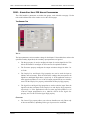
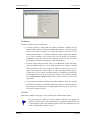
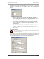
INSTALLING THE USB DRIVERS
CRIMSON USER MANUAL - MODULAR CONTROLLER
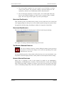
INSTALLING THE USB DRIVERS
When you first connect a Master module to your PC using a USB cable, Windows will
prompt you for the location of the drivers for the device. The default location for these drivers
is C:\Program Files\Red Lion Controls\Crimson 2.0\Device. When the Hardware Setup
Wizard appears, choose the Browse option, and either point the Wizard at that location or
whatever other location you specified during installation of the software. It is important that
you perform this step correctly, or you may have to manually remove the drivers using the
Device Manager, and repeat the installation once more. Windows XP users should note that
Crimson’s USB drivers have not been digitally signed by Microsoft, and you will therefore a
dialog offering you the chance to stop the installation. You should be sure to select the
Continue option to indicate that you do indeed wish to install the drivers.
PAGE 2
http://www.redlion.net/controller
QUICK START
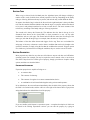
OVERVIEW
QUICK START
The Modular Controller is a versatile platform, truly requiring a 300+ page manual. However,
you’ll no doubt want to jump right into programming before reading it in its entirety. The
following section provides you with enough information to develop a working system.
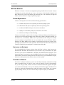
OVERVIEW
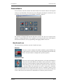
For the simplest of applications, only the first two icons eg. Modules and Communications,
are necessary. The former configures the system, allowing you to add, delete and edit
modules, while the latter allows module data to be mapped to an external device(s).
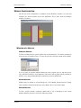
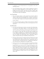
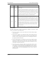
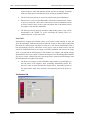
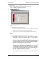
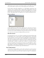
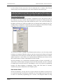
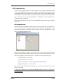
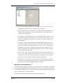
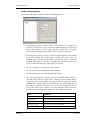
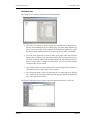
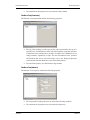
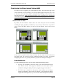
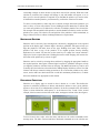
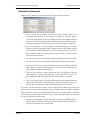
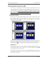
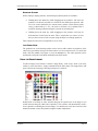
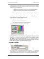
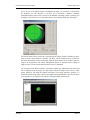
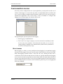
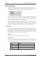
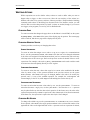
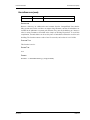
MODULES
The first step in the configuration of a database is to create and configure the various modules
used in the application. This is done under the Modules window of Crimson.
To insert a module into the system, double click on the blank base. You will be prompted to
choose the type of module to insert. You may also provide a descriptive name for the module.
REVISION 6
PAGE 3
COMMUNICATIONS
CRIMSON USER MANUAL - MODULAR CONTROLLER
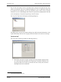
Edit the individual module’s properties by double-clicking it. Each module and its properties
are explained in detail in later sections.
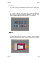
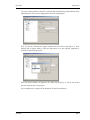
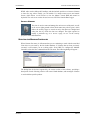
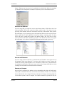
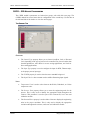
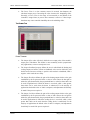
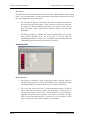
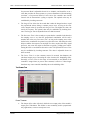
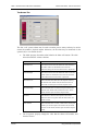
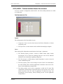
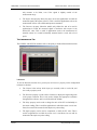
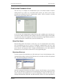
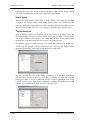
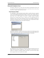
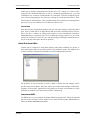
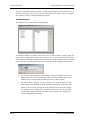
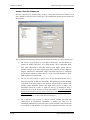
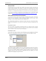
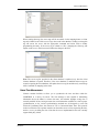
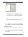
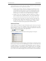
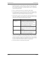
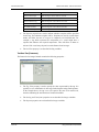
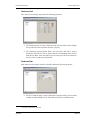
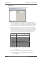
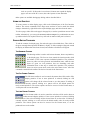
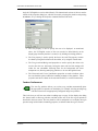
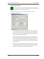
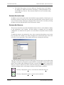
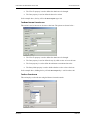
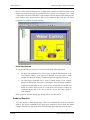
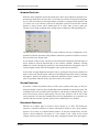
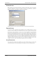
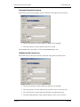
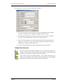
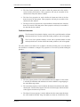
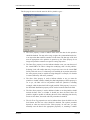
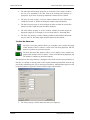
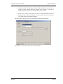
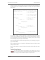
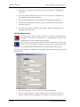
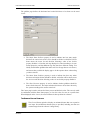
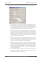
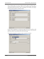
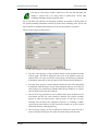
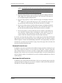
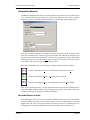
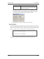
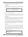
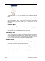
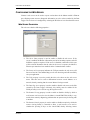
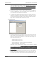
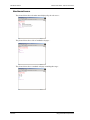
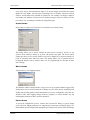
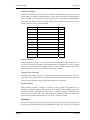
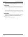
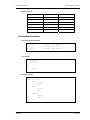
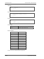
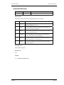
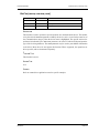
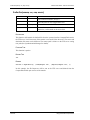
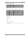
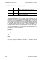
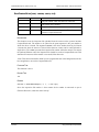
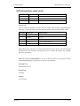
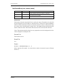
COMMUNICATIONS
Next, you’ll want to configure a port to communicate data to your PLC, PC, etc. The ports are
configured under the Communications window of the software. Click the Edit button in the
driver selection area to choose a protocol.
In the example below, Allen Bradley DF1 Master has been selected as the protocol. By doing
so, a device called PLC1 has been created. You should verify that the driver properties eg.
parity, baud rate, address, etc. make sense for your application.
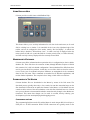
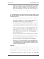
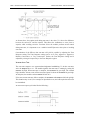
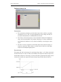
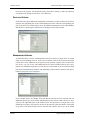
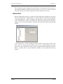
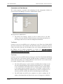
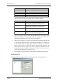
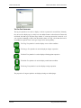
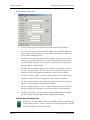
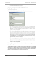
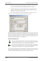
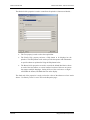
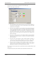
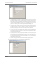
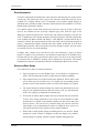
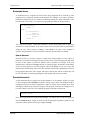
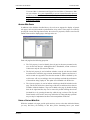
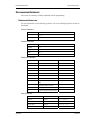
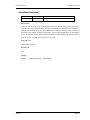
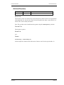
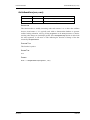
MAPPING DATA
To map data between the Modular Controller and an external device, you’ll need to create
two so-called Gateway Blocks; one for moving module data into your device, and one for
getting module data from your device.
PAGE 4
http://www.redlion.net/controller
QUICK START
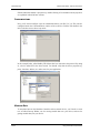
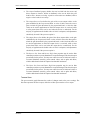
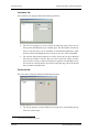
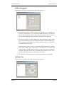
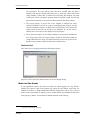
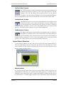
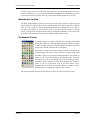
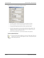
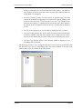
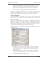
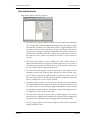
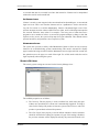
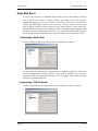
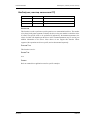
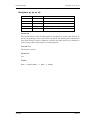
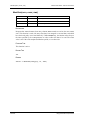
MAPPING DATA
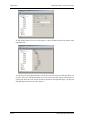
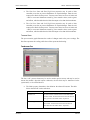
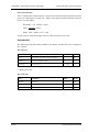
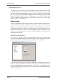
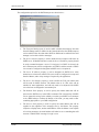
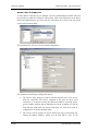
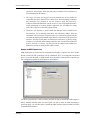
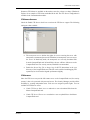
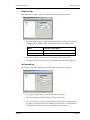
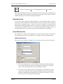
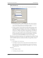
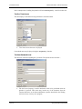
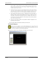
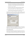
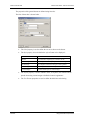
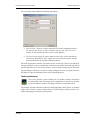
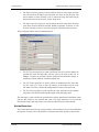
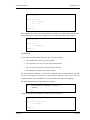
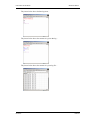
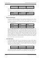
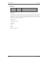
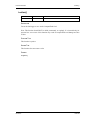
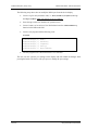
To create a Gateway Block, click PLC1, and then click the Add Gateway Block button on the
right hand pane. This creates a single gateway block for mapping data…
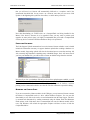
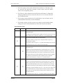
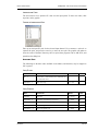
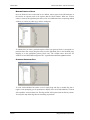
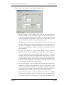
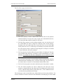
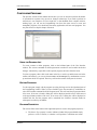
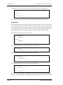
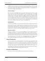
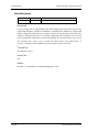
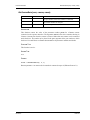
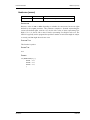
Next, you’ll need to identify the register locations that you wish to map data to or from,
starting with a register address. Click the Edit button to see the registers supported by
Crimson for the selected protocol…
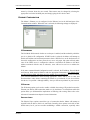
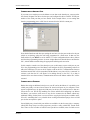
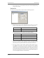
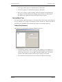
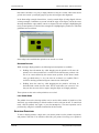
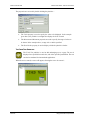
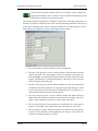
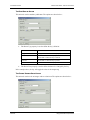
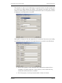
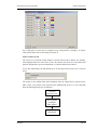
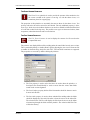
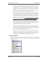
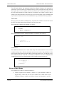
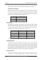
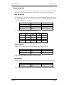
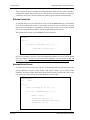
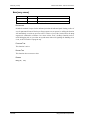
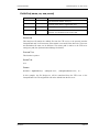
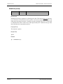
Enter the desired number of registers in the Block Size property, as well as the desired
direction using the Direction property.
In our example below, registers N7:0 through N7:16 have been allocated.
REVISION 6
PAGE 5
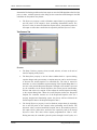
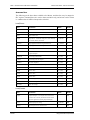
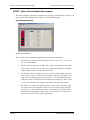
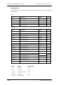
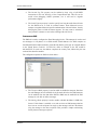
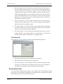
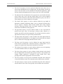
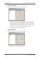
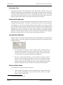
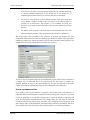
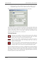
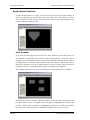
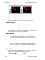
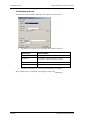
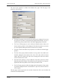
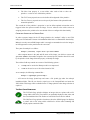
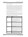
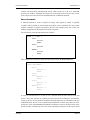
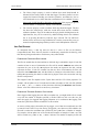
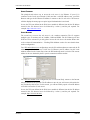
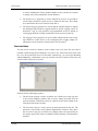
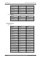
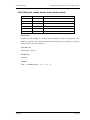
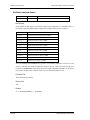
MAPPING DATA
CRIMSON USER MANUAL - MODULAR CONTROLLER
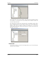
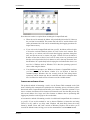
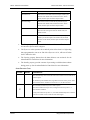
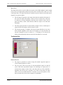
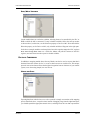
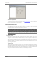
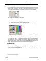
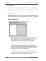
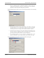
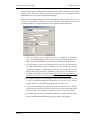
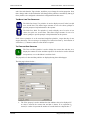
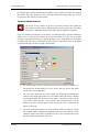
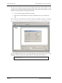
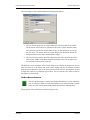
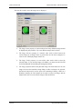
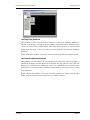
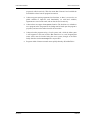
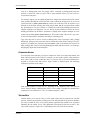
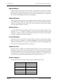
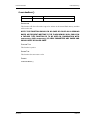
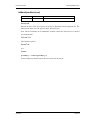
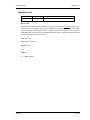
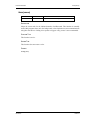
To map module data, select one of the registers. A list of available data will be shown in the
right hand pane…
To map items from the right hand pane to the items on the left, simply double click them, one
at a time. The cursor will automatically move to the next consecutive register, allowing you to
quickly map all of the items. Instead of clicking the data in the right hand pane, you may also
drag and drop the data onto specific registers.
PAGE 6
http://www.redlion.net/controller
QUICK START
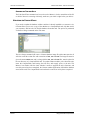
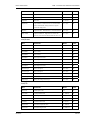
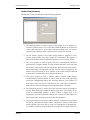
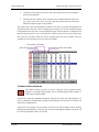
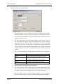
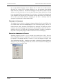
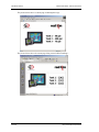
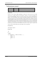
DOWNLOADING
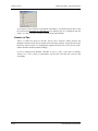
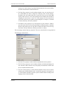
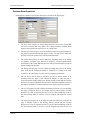
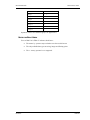
In the example above, each of the first module’s input values have been mapped to registers
N7:0 through N7:7. The direction of the arrows indicates that the Modular Controller will
write these values into the PLC.
Next, another block is created to move data from the PLC to the Modular Controller. This is
done by changing the block’s Direction property to Device to MC. In the example below,
Module1’s offset values are mapped to registers N11:0 through N11:7. The Direction
property indicates that the MC will get the value from the PLC registers, and write them into
the module’s offset values.
DOWNLOADING
To download to the Master via serial is trivial. Simply make sure you’ve selected the proper
COM port under Link-Options.
REVISION 6
PAGE 7
CONNECT THE TWO
CRIMSON USER MANUAL - MODULAR CONTROLLER
If you plan to use the USB port to download to the Master, you should take the time to read
the section titled Installing the USB Drivers. The Ethernet port isn’t configured from the
factory, so it can’t be used as a means to download an initial database.
CONNECT THE TWO
That’s it. Connect the device to the MC, and if you’ve selected a master protocol, the
Modular Controller will do the rest. Simply look at the target registers, and you should see the
data being written to them. Try changing the registers that have been set for Device to MC,
and the modules should respond accordingly.
If you’ve configured the Modular Controller to act as a slave, you’ll have to initialize
whatever it is you’re using to communicate with the MC, and read and write the data
accordingly.
PAGE 8
http://www.redlion.net/controller
CRIMSON BASICS
MAIN SCREEN ICONS
CRIMSON BASICS
To run Crimson, select the Crimson icon from the Red Lion Controls folder on the Programs
section of your Start Menu. The main C2 screen will appear, showing the icons that are used
to configure the various aspects of the Modular Controller’s behavior…
The software is designed such that the first three icons are the only ones required for the
majority of simple applications. The remainder of the icons provide access to the Master’s
more advanced features, such as programming, data logging and the web server.
MAIN SCREEN ICONS
The sections below provide an overview of each icon in turn…
MODULES
This icon is used to configure the modules within the system. Modules may
be added, deleted, or have their order on the rail modified. Each module may
then be accessed in order to configure their specific properties.
COMMUNICATIONS
This icon is used to specify which protocols are to be used on the Master’s
serial ports and on the Ethernet port. Where master protocols are used (ie.
protocols by which the Master module initiates data transfer to and from a
remote device) you can also use this icon to specify one or more devices to
be accessed. Where slave protocols are used (ie. protocols by which the
Master receives and responds to requests from remote devices or computer systems) you can
specify which data items are to be exposed for read or write access. You can also use this icon
to move data between one remote device and another via Crimson’s protocol converter.
REVISION 6
PAGE 9
MAIN SCREEN ICONS
CRIMSON USER MANUAL - MODULAR CONTROLLER
DATA TAGS
This icon is used to rename data items from the modules, as well as to define
items be accessed within the remote devices. It also allows the creation of
internal data items to store information within the Master itself. Each tag has
a variety of properties associated with it. The most basic property is
formatting data, which is used to specify how the data held within a tag is to
be shown on the Master’s virtual HMI, and on such things as web pages. By specifying this
information within the tag, Crimson removes the need for you to re-enter formatting data each
time a tag is displayed. More advanced tag properties include alarms that may activate when
various conditions relating to the tag occur, or triggers, which perform programmable actions
on similar conditions.
USER INTERFACE
This icon is used to create and edit display pages of the virtual HMI, and to
specify what actions should be taken when the HMI’s keys are pressed,
released or held down. The page editor allows you to display various
graphical items known as primitives. These vary from simple items, such as
rectangles and lines, to more complex items that can be tied to the value of a
particular tag or expression. By default, such primitives use the formatting information
defined when the tag was created, but this information can be overridden if required.
PROGRAMMING
This icon is used to create and edit programs using C2’s unique C-like
programming language. These programs can perform complex decision
making or data manipulation operations based upon any data items within
the system. They serve to extend the functionality of Crimson beyond that of
the standard functions included in the software, thereby ensuring that even
the most complex applications can be tackled with ease.
DATA LOGGER
This icon is used to create and manage data logs, each of which can record
any number of variables to the Master’s CompactFlash card. Data may be
recorded as quickly as once per second. The recorded values will be stored
in CSV (comma separated variable) files that can easily be imported into
applications such as Microsoft Excel. The files can be accessed by
swapping-out the CompactFlash card, by mounting the card as a drive on a PC connected on
the Master’s USB port, or by accessing them via Crimson’s web server via the Ethernet port.
WEB SERVER
This icon is used to configure Crimson’s web server and to create and edit
web pages. The web server is capable of providing remote access to the
Master via a number of mechanisms. First, you can use Crimson to create
automatic web pages which contain lists of tags, each formatted according to
the tag’s properties. Second, you can create a custom site using a third party
PAGE 10
http://www.redlion.net/controller
CRIMSON BASICS
SELECTING THE MODULAR CONTROLLER
HTML editor such as Microsoft FrontPage, and then include special text to instruct Crimson
to insert live tag values. Finally, you can enable C2’s unique remote access and control
feature, which allows a web browser to view the Master’s virtual HMI and control its
keyboard. The web server can also be used to access CSV files from the Data Logger.
SECURITY MANAGER
This icon is used to create and manage the various users of the panel, as well
as the access rights granted to them. Real names may also be given, which
allows the security logger to record not only what data was changed and
when, but also by whom the data was changed. The rights required to
modify a particular tag, or to access a page, are set via the security
properties of the individual item.
SELECTING THE MODULAR CONTROLLER
When Crimson first starts, it will assume that you are continuing to work with the same Red
Lion device as was used by the last loaded database. If Crimson has not been previously
executed, it will assume you are working with a G303 HMI. To configure the Modular
Controller, select the New command from the File menu. The following dialog will appear…
The dialog lists the devices supported by the current version of the software, providing a
description of each. Selecting a device will create a blank database, and reconfigure Crimson
to work with that specific product.
REVISION 6
PAGE 11
USING BALLOON HELP
CRIMSON USER MANUAL - MODULAR CONTROLLER
USING BALLOON HELP
Crimson provides a useful feature called Balloon Help...
This feature allows you to see help information for each icon in the main menu, or for each
field in a dialog box or window. It is controlled via the icon at the right-hand edge of the
toolbar, and can be configured to three modes, namely “Do Not Display”, in which case
balloon help is disabled; “When Mouse Over”, in which case help is displayed when the
mouse pointer is held over a particular field for a certain period of time; or “When Selected”,
in which case help is always displayed for the currently selected field.
WORKING WITH DATABASES
Crimson stores all the information about a particular device’s configuration in what is called a
database file. These files have the extension of CD2, although Windows Explorer will hide
this extension if it is left in its default configuration. Crimson database files differ from those
used by previous Red Lion products, in that they are text files which are thus far easier to
recover in the case of accidental corruption. Databases are manipulated via the commands
found on the File menu. These commands are standard for all Windows applications, and
need no further explanation. The exception is Save Image, which will be covered later.
DOWNLOADING TO THE MASTER
Crimson database files are downloaded to the Master by means of the Link menu. The
download process typically takes only a few seconds, but can take somewhat longer on the
first download if Crimson has to update the firmware in the Master, or if the Master does not
contain an older version of the current database. After this first download, however, Crimson
uses a process known as incremental download to ensure that only changes to the database are
transferred. This means that changes can be made in seconds, thereby reducing your
development cycle time and simplifying the debugging process.
CONFIGURING THE LINK
The programming link between the PC and the Master is made using an RS-232 serial port, a
USB port or a TCP/IP connection. While TCP/IP connections are typically made via the
PAGE 12
http://www.redlion.net/controller
CRIMSON BASICS
DOWNLOADING TO THE MASTER
Master’s Ethernet port, they may also be established via a dial-in link. Before downloading,
you should use the Link-Options command to ensure that you have the method selected…
VERIFYING THE USB LINK
If you are using USB, you might also want to ensure that the Master’s USB drivers have been
correctly installed. To do this, connect the Master module, and, if the drivers have not
previously been installed, follow the instructions at the start of this manual. Then, open the
Device Manager for your operating system, and expand the USB icon to show the icon for the
Master module device. Ensure that this icon does not display a warning symbol. If it does,
remove the device, unplug and reconnect the Master module, and verify that you have
correctly followed the driver installation procedure. The illustrations below show typical
Device Manager views with the CompactFlash dismounted and mounted, respectively….
SETTING THE IP ADDRESS
If you are using a TCP/IP connection, you should enter the IP address of the target device in
the appropriate field in the dialog box. If you leave the IP address as 0.0.0.0, Crimson will
examine the currently loaded database to see if the Master’s address can be determined from
the configuration information. This feature removes the need to change the IP addresses when
switching between databases intended for different terminals.
SENDING THE DATABASE
Once the link is configured, the database can be downloaded using either the Link-Send or
Link-Update commands. The former will send the entire database, whether or not individual
objects within the file have changed. The latter will only send changes, and will typically take
a much shorter period of time to complete. The Update command is typically the only one
REVISION 6
PAGE 13
DOWNLOADING TO THE MASTER
CRIMSON USER MANUAL - MODULAR CONTROLLER
that you will need, as Crimson will automatically fall-back to a complete send if the
incremental download fails for any reason. As a shortcut, note that you can access Link
Update via the lightning-bolt symbol on the toolbar, or via the F9 key on the PC.
Note that downloading via TCP/IP relies on a CompactFlash card being installed in the
Master if the device’s firmware is to be upgraded. Since you may want to perform such
upgrades at some point in time, it is highly recommended that you install a CompactFlash
card in any device to which TCP/IP downloads are likely to be performed.
EXTRACTING DATABASES
The Link-Support Upload command can be used to instruct Crimson whether or not it should
include the information necessary to support database upload when sending a database to a
Master module. Supporting upload will slow the download process somewhat and may fail
with extremely large databases containing many embedded images, but it will ensure that if
you lose your database file, you will be able to extract an editable image from the terminal.
Note that if you lose your database file and you do not have upload support enabled, you will
not be able to reconstruct your file without starting from scratch. To extract a database from a
Master, use the Link-Extract command. This command will upload the database, and then
prompt you for a name under which to save the file. The file will then be opened for editing.
MOUNTING THE COMPACTFLASH
If you are connected to a Master module via the USB port, you can instruct Crimson to mount
the Master’s CompactFlash card as a drive within Windows Explorer. You can use this
functionality to save files to the card or to read information from the Data Logger. The drive
is mounted and dismounted by sending commands using the Mount Flash and Dismount
Flash options on the Link menu. Once a command has been sent, the Master module will be
reset, and Windows will refresh the appropriate Explorer windows to show or hide the
CompactFlash drive.
PAGE 14
http://www.redlion.net/controller
CRIMSON BASICS
DOWNLOADING TO THE MASTER
Note that some caution is required when mounting the CompactFlash card...
•
When the card is mounted, the Master will periodically inform the PC if data on
the card has been modified. This means that both the PC and the Master will
suffer performance hits if the card is mounted during data logging operations for
longer than necessary.
•
If you write to the CompactFlash card from your PC, the Master will not be able
to access the card until Windows releases its “lock” on the card’s contents. This
may take up to a minute, and will restrict data logging operations during that
time, and prevent access to custom web pages. Crimson will use the Master’s
RAM to ensure that no data is lost, but if too many writes are performed such
that the card is kept locked for four minutes or more, data may discarded. Note
that Windows 98 is particularly bad at keeping the card locked when there is no
need for it. Windows 2000 or Windows XP is thus the operating system of
choice when using this feature.
•
You should never attempt to use Windows to format a CompactFlash card that
you have mounted via the Master, whether it be via Explorer or from the
command prompt. Windows does not correctly lock the card during format
operations, and the format may thus be unreliable and lead to subsequent data
loss. See below for details of how to format a card in a reliable manner.
FORMATTING THE COMPACTFLASH
The preferred method of formatting a card is via the Format Flash command on the Link
menu. Selecting this command will explain that the formatting process will destroy all the
data stored on the CompactFlash card and offer you a chance to cancel the operation. If you
elect to continue, the Master will be instructed to format the card. Note that this process may
take several minutes for a large card. Slow formats on Masters that are performing data
logging may therefore result in gaps in the recorded data.
A less attractive method of formatting a card is via a dedicated CompactFlash drive connected
to your PC. If you use this method, be sure to instruct Windows to format the card using
FAT16. For very small or very large cards, Windows will most likely choose the wrong
format by default. Worse still, some versions of Windows Explorer will not allow you to
override the default format, forcing you to use the command line version FORMAT instead.
REVISION 6
PAGE 15
UPDATING VIA COMPACTFLASH
CRIMSON USER MANUAL - MODULAR CONTROLLER
SENDING THE TIME AND DATE
The Link-Send Time command can be used to set the Master’s clock to match that of the PC
on which Crimson is executing. Obviously, make sure your clock is right before you do this!
UPDATING VIA COMPACTFLASH
If you need to update the database within a unit that is already installed at a customer’s site,
Crimson allows you to save a copy of the database to a CompactFlash card, ship that card to
your customer, and have the G3 load the database from that card. The process is performed
via the Save Image command on the File menu.
The Save Image command will create a Crimson database image file with a CDI extension. It
will also create three other files with extensions of BIN, LDR and ROM. The image file must be
given the name DBASE.CDI, and it, along with the BIN, LDR and ROM files, must be placed in
the root directory of a CompactFlash card. To update a Master module, power down the unit,
insert the CompactFlash card bearing the four files, and reapply power to the unit. The
Master’s boot loader will first check whether it needs to upgrade the unit’s firmware, and
once this process has been completed, the Crimson runtime application will load the database
stored on the card. The CompactFlash card can then be removed or left in place as required.
PAGE 16
http://www.redlion.net/controller
MODULE CONFIGURATION
WORKING WITH MODULES
MODULE CONFIGURATION
The first step in the configuration of a database for the Modular Controller is to create and
configure the various modules used in the application. This is done under the Modules
window of Crimson.
WORKING WITH MODULES
INSERTING MODULES
To insert a module into the system, double click on the blank base. You will be prompted to
choose the type of module to insert. You may also provide a descriptive name for the module.
If you are going to program multiple modules the same, program just one, and then use the
Copy and Paste functions to create duplicates. This can be done by right-clicking a module or
the base, or by using standard Windows commands eg. Ctrl+C and Ctrl+V.
MOVING MODULES
Modules may be deleted or moved through use of the Module drop-down menu. Simply
select a module, and then from the menu, select Delete, Move Left or Move Right.
EDITING MODULES
To edit a specific module’s properties, double-click it. For a description of the various
modules and their properties, refer to the following sections.
REVISION 6
PAGE 17
CSPID – PID MODULE PROGRAMMING
CRIMSON USER MANUAL - MODULAR CONTROLLER
CSPID – PID MODULE PROGRAMMING
The CSPID module’s parameters are broken into groups, each with their own page. The
CSPID2 module has several extra tabs for configuration of the second loop. Use the tabs on
the left hand side of the window to view the various pages.
THE GENERAL TAB
OPERATION
•
The Control Type property allows you to choose from Heat, Cool, or Heat and
Cool, depending on the type of process to be controlled. For processes other than
thermal applications, select Heat for reverse acting applications, and Cool for
direct acting applications.
•
The Input Type property is used to configure the input for RTD, Thermocouple,
or the proper process input type.
•
The TC/RTD property is used to select the sensor standard being used.
•
The Input Filter is a time constant used to stabilize fluctuating input signals.
UNITS
PAGE 18
•
Temperature Units is used to select between the Kelvin, Fahrenheit, or Celsius
temperature scale.
•
The Process Units property allows you to enter the engineering units for the
process. This is only used to identify the appropriate fields throughout the
software. This parameter is saved as part of the Crimson file, but is not used
within the module.
•
The Decimal Places property is used to allow Crimson to display the engineering
units in the proper resolution. This is only used to display the appropriate
resolution throughout the software, and is not used within the module.
http://www.redlion.net/controller
MODULE CONFIGURATION
•
CSPID – PID MODULE PROGRAMMING
The Process at 0% and Process at 100% properties are used to scale DC input
signals. Enter the desired PV reading for the minimum and maximum input
signal levels. For example, if the application involves a flow sensor with a 4 to
20 mA output proportional to 5 to 105 GPM, select Process 4-20mA for the
Input Type, enter 5 for the Process at 0% setting, and enter 105 for the Process
at 100% setting.
INITIALIZATION
The initialization parameters provide initial values for settings usually controlled by a PC or
PLC. In typical applications, these settings will only be used until communications is
established for the first time.
•
The Include in Download property is used to determine whether the initialization
values will be downloaded to the module. Selecting “no” allows the modification
and download of databases at will, without accidental overwriting of the
established process parameters such as the setpoint, PID values, etc.
•
The PID Parameters property dictates which PID parameters the module will
load, and subsequently use, to control the process. The module controls the
process using the Active PID values and Active Power Filter. (See ActConstP,
ActConstI, ActConstD, and ActFilter variables in the Available Data chart at
the end of this section.) The active set is loaded with either the User PID
Settings, or the Auto-Tune Results values, depending on the state of the
ReqUserPID bit. If the bit is true, the Active set is loaded with the user’s
variables. If the bit is false, the values that were established by auto-tune are
loaded. Adjusting the PID Parameters property writes the ReqUserPID bit
appropriately upon initialization.
•
The Control Mode property dictates whether the module will in auto or manual
mode upon initialization. In auto mode, the controller calculates the required
output to reach and maintain setpoint, and acts accordingly. In manual mode, the
output can be controlled directly by writing to the power variable.
•
The Initial Setpoint property is used as the setpoint value upon initialization.
•
Manual Power is the level the PID module will assume in manual mode. Values
in excess of 100% and –100% can be entered to overcome the limitations caused
by Power Transfer values, such as gains and offsets that would otherwise limit
the outputs to less than their maximums.
SMARTONOFF
SmartOnOff is designed for situations where on-off control would normally be used, but
where the advantages of PID are also desired. When heat or cool is placed into this mode, the
control output will either be driven on or off, with no intermediate values or time
proportioning. However, rather than use the process value to decide when to turn the output
on, SmartOnOff looks at the output of the PID calculation and activates the output when it
exceeds half the defined gain for that channel. For example, with default settings,
REVISION 6
PAGE 19
CSPID – PID MODULE PROGRAMMING
CRIMSON USER MANUAL - MODULAR CONTROLLER
SmartOnOff for heating would turn the heat output on once the PID algorithm called for 50%
power or more, with the hysteresis value being used to ensure that small changes in the PID
calculation do not produce relay chatter.
•
The Hysteresis property is used to eliminate output chatter by separating the on
and off points of the output(s) when performing SmartOnOff control. The
Hysteresis value is centered around the setpoint, that is, the transition points of
the output are offset above and below the setpoint by half the Hysteresis value.
THE CONTROL TAB
SETPOINT
PAGE 20
•
The Ramp Timebase property selects seconds, minutes, or hours as the unit of
time for ramping of the process.
•
The Ramp Rate property is used to reduce sudden shock to a process during
setpoint changes and system startup, a setpoint ramp rate can be used to increase
or decrease the Actual Setpoint at a controlled rate. The value is entered in
units/time. A value of 0 disables setpoint ramping. If the Setpoint Ramp Rate is a
non-zero value, and the Requested Setpoint is changed or the module is powered
up, the controller sets the Actual Setpoint to the current process measurement,
and uses that value as its setpoint. It then adjusts the Actual Setpoint according
to the setpoint Ramp Rate. When the Actual Setpoint reaches the Requested
Setpoint, the controller resumes use of the Requested Setpoint value. (In a
properly designed and functioning system, the process will have followed the
Actual Setpoint value to the Requested Setpoint value.)
•
The On/Off Hysteresis property is used to eliminate output chatter by separating
the on and off points of the output(s) when performing on/off control. The
hysteresis value is centered around the setpoint, that is, the transition points of
the output will be offset above and below the setpoint by half of the On/Off
Hysteresis value. This value effects outputs programmed for Heat or Cool.
During auto-tune, the controller cycles the process through 4 on/off cycles, so it
http://www.redlion.net/controller
MODULE CONFIGURATION
CSPID – PID MODULE PROGRAMMING
is important to set the On-Off Hysteresis to an appropriate value before
initializing auto-tune.
•
The On-Off Deadband property provides a means of offsetting the on-points of
heat and cool outputs programmed for on/off operation. This results in a
deadband if the value is positive, and overlap if the value is negative. When
determining the actual transition points of the outputs, the On/Off Hysteresis
value must also be taken into consideration.
AUTO-TUNE SETTINGS
•
The Tune Response property is used to ensure that an auto-tune yields the
optimal P, I, and D values for varying applications. A setting of Very Aggressive
results in a PID set that will reach setpoint as fast as possible, with no concern
for overshoot, while a setting of Very Conservative sacrifices speed in order to
prevent overshoot.
•
Note: If the Tune Response property is changed, auto-tune needs to be reinitiated
for the changes to affect the PID settings. See the Auto-Tuning Section for more
information.
USER PID SETTINGS
REVISION 6
•
The Proportional Band property, entered as a percentage of the full input range,
is the amount of input change required to vary the output full scale. For
temperature inputs, the input range is fixed per the entered thermocouple or RTD
type. For process inputs, the input range is the difference between the Process at
0%, and Process at 100% values. The Proportional Band is adjustable from
0.0% to 1000.0%, and should be set to a value that provides the best response to
a process disturbance while minimizing overshoot. A Proportional Band of 0.0%
forces the controller into On/Off Control with its characteristic cycling at
setpoint. The optimal value may be established by invoking Auto-tune.
•
The Integral Time is the time in seconds that it takes the integral action to equal
the proportional action, during a constant process error. As long as the error
exists, integral action is repeated each Integral Time. The higher the value, the
slower the response. The optimal value may be established by invoking autotune. The Integral Time is adjustable from 0 to 6000.0 seconds.
•
The Derivative Time is the seconds per repeat that the controller looks ahead at
the ramping error to see what the proportional contribution will be and it
matches that value every Derivative Time. As long as the ramping error exists,
the derivative contribution is repeated every derivative time. Increasing the value
helps to stabilize the response, but too high of a value, coupled with noisy signal
processes, may cause the output to fluctuate too greatly, yielding poor control.
Setting the time to zero disables derivative action. The optimal Derivative Time
may be established by invoking auto-tune. The value is adjustable from 0 to
600.0 seconds.
PAGE 21
CSPID – PID MODULE PROGRAMMING
•
CRIMSON USER MANUAL - MODULAR CONTROLLER
The Power Filter is a time constant, entered in seconds, that dampens the
calculated output power. Increasing the value increases the dampening effect.
Generally, a Power Filter in the range of one-twentieth to one-fiftieth of the
controller’s integral time (or process time constant) is effective. Values longer
than these may cause controller instability due to the added lag effect.
THE POWER TAB
POWER TRANSFER
PAGE 22
•
The Output Offset value effectively shifts the zero output point of the module’s
output power calculation. This feature is most commonly used in proportionalonly applications, to remove steady-state error.
•
The Output Deadband property defines the area in which both the heating and
cooling outputs are inactive, known as deadband, or the area in which they will
both be active, known as overlap. A positive value results in a deadband, while a
negative value results in an overlap.
•
The Output Heat Gain defines the gain of the heating output relative to the gain
established by the Proportional Band. A value of 100% causes the heat gain to
mimic the gain determined by the proportional band. A value less than 100% can
be used in applications in which the heater is oversized, while a value greater
than 100% can be used when the heater is undersized. For the majority of
applications the default value of 100% is adequate, and adjustments should only
be made if the process requires it.
•
The Output Cool Gain defines the gain of the cooling output relative to the gain
established by the Proportional Band. A value of 100% causes the cool gain to
mimic the gain determined by the proportional band. A value less than 100% can
be used in applications in which the cooling device is oversized, while a value
greater than 100% can be used when the cooling device is undersized. For the
majority of applications the default value of 100% is adequate, and adjustments
should only be made if the process requires it.
http://www.redlion.net/controller
MODULE CONFIGURATION
CSPID – PID MODULE PROGRAMMING
•
The Heat Low Limit and Heat High Limit properties may be used to limit
controller power due to process disturbances or setpoint changes. Enter the safe
output power limits for the process. You may enter values in excess of 100% and
–100% to overcome limitations caused by power transfer values, such as gains
and offsets, which would otherwise limit the output to less than their maximums.
•
The Cool Low Limit and Cool High Limit properties may be used to limit
controller power due to process disturbances or setpoint changes. Enter the safe
output power limits for the process. You may enter values in excess of 100% and
–100% to overcome limitations caused by power transfer values, such as gains
and offsets, which would otherwise limit the output to less than their maximums.
TRANSFER GRAPH
The power transfer graph illustrates the results of changes made to the power settings. The
blue line represents the cooling, while the red line represents the heating.
THE ALARMS TAB
The four “soft” process alarms may be used to monitor process status, and may be used to
actuate the module’s physical outputs. Otherwise, the bit alone may be monitored via the
system itself, or via external devices.
•
The Mode property determines what behavior the alarm will assume. The table
below describes the various selections.
MODE
DESCRIPTION
Absolute Low
The alarm activates when the Process Value falls below
the Alarm Value. The alarm deactivates when the Process
Value goes above the Alarm Value + Hysteresis.
Absolute High
The alarm activates when the Process Value exceeds the
Alarm Value. The alarm deactivates when the Process
Value falls below the Alarm Value – Hysteresis.
REVISION 6
PAGE 23
CSPID – PID MODULE PROGRAMMING
CRIMSON USER MANUAL - MODULAR CONTROLLER
MODE
DESCRIPTION
Deviation Low
If the Process Value falls below the Setpoint Value by the
amount of the Alarm Value, the alarm activates. In this
mode, the alarm point tracks the Setpoint Value.
Deviation High
If the Process Value exceeds the Setpoint Value by the
amount of the Alarm Value, the alarm activates. In this
mode, the alarm point tracks the Setpoint Value.
In Band
If the difference between the Setpoint Value and the
Process Value is not greater than the Alarm Value, the
alarm activates.
Out of Band
If the Process Value exceeds, or falls below, the Setpoint
Value by an amount equal to the Alarm Value, the alarm
activates. In this mode, the alarm point tracks the Setpoint
Value.
•
The Value property is the point at which the alarm will turn on. The alarm values
are entered as process units or degrees.
•
The Hysteresis value separates the on and off points of the alarm ie. a high acting
alarm programmed to turn on at 500 with a Hysteresis of 10, will turn off when
the PV falls below 490.
•
The Latching property dictates how the alarm behaves once activated. See the
Alarm Behavior Chart below for more information.
•
The Standby property provides a means of preventing so called nuisance alarms
during power up. See the Alarm Behavior Chart below for more information.
ALARM BEHAVIOR CHART
LATCHING
STANDBY
ALARM BEHAVIOR
Alarm automatically turns on and off as the Process Value crosses in and out of
the alarm region.
The AlarmAccept bit disables alarm, regardless of the state of the process. If the
alarm condition exists, and the bit is written to a “0”, the alarm activates.
Once activated, the alarm stays active until accepted.
If the alarm condition no longer exists, writing the Alarm Accept bit to “1”
resets the alarm condition.
As long as the Alarm Accept bit is “1”, the alarm automatically turns on and off
as the Process Value crosses in and out of the alarm region.
PAGE 24
http://www.redlion.net/controller
MODULE CONFIGURATION
LATCHING
CSPID – PID MODULE PROGRAMMING
STANDBY
ALARM BEHAVIOR
Alarm automatically turns on and off as the Process Value crosses in and out of
the alarm region.
The alarm is automatically disabled when a setpoint change occurs, or when the
module is first powered up. This prevents nuisance alarms from occurring. The
alarm remains disabled until the process enters a non-alarm state. The next time
the Process Value enters an alarm condition, the alarm will activate accordingly.
The AlarmAccept bit disables the alarm, regardless of state. If the alarm
condition exists, and the bit is written to a “0”, the alarm activates.
Once activated, the alarm stays active until accepted.
The alarm is automatically disabled when a setpoint change occurs, or when the
module is first powered up. This prevents nuisance alarms from occurring. The
alarm remains disabled until the process enters a non-alarm state. The next time
the Process Value enters an alarm condition, the alarm will activate accordingly.
Momentarily writing the AlarmAccept bit to “1” turns off an active alarm. If the
alarm condition still exists, the alarm remains off and is placed into standby
mode. That is, the alarm will remain off until the alarm condition goes away,
and is then reentered.
If the AlarmAccept bit remains a “1”, the alarm is disabled, and will not function.
HEATER CURRENT
The Heater Current alarm is useful for monitoring the condition of external AC control
circuitry via the Heater Current Monitor input.
REVISION 6
•
The Channel property is used to select which one of the three discrete outputs
will be monitored.
•
The Limit Low property is the desired mA value, from 0-100.00 mA that
represents the allowable circuit-off current. If the heater current monitor input
measures a current value greater than the Limit Low value during the off state of
the output, the alarm becomes active.
•
The Limit High property is the desired mA value, from 0-100.00 mA that
represents the required circuit-on current value. If the heater current monitor
input measures a current value less than the Limit High value during the on state
of the output, the alarm becomes active.
•
The Latching property determines whether an activated alarm will stay active
until accepted. To accept a latched alarm, its AlarmAccept bit must be written to
a 1. If latching is not selected, the alarm will automatically deactivate when the alarm
condition no longer exists, and the AlarmAccept bit may be used as a means of
disabling the alarm.
PAGE 25
CSPID – PID MODULE PROGRAMMING
CRIMSON USER MANUAL - MODULAR CONTROLLER
INPUT FAULT
The Input Fault section is used to define the response of the CSPID module’s control outputs
in the event of an input failure. The Input Fault alarm is considered a process alarm for items
that may be mapped to “any process alarm”.
•
The Set Output To property is the output value that the controller will assume in
the event of an input sensor failure. Values in excess of 100% and –100% may
be entered to overcome limitations caused by power transfer values, such as
gains and offsets, which would otherwise limit the output to less than their
maximums.
•
The Latching property, if enabled, will cause the input fault bit to stay active
until accepted, regardless of the state of the input. To reset the fault, the
InputAccept bit must be written to a 1. If latching is not selected, the fault will
automatically deactivate when the input failure is corrected.
THE OUTPUTS TAB
DIGITAL OUTPUTS
PAGE 26
•
The Output n properties are used to assign the module’s physical outputs to
various internal properties or values. The CSPID2’s list is expanded to include
the channel number eg. Channel 1 Heat Power, or Channel 2 Heat Power.
•
The Cycle Time value is the sum of a time-proportioned output’s on and off
cycles. With time proportional outputs, the percentage of output power is
converted into output on time of the cycle time value eg. if the controller’s
algorithm calls for 65% power, and has a Cycle Time of 10 seconds, the output
will be on for 6.5 seconds and off for 3.5 seconds. A Cycle Time equal to, or less
than, one-tenth of the process time constant is recommended.
http://www.redlion.net/controller
MODULE CONFIGURATION
CSPID – PID MODULE PROGRAMMING
LINEAR OUTPUT - (CSPID1 ONLY)
•
The Output Type property is used to select between 0-10 V, 0-20 mA, or 4-20
mA outputs. Make sure that the output jumpers, located on the side of the
module, are set for the same output type.
•
The Mapping property is used to assign the module’s analog output to one of
various internal properties or values eg. the Mapping property should be set to
Heat Power to control a heat-only process via the analog output.
•
The Drive Min At and Drive Max At values are used to scale the analog output.
The units expressed are the same as those of the Mapping value, so the
numerical limits vary eg. values of 0% and 100% are typically used to control a
valve’s position in heat-only applications.
•
The Output Filter is a time constant entered in seconds that dampens the
response of the analog output. Increasing the value increases the dampening.
•
The Output Deadband value can be used to prevent the analog output from
changing when only small adjustments are called for. This is useful in preventing
mechanical wear when driving a linear input valve. The analog output will not
adjust unless the change called for exceeds half of the deadband value. i.e. With
a deadband of 10 %, and an output value of 50 %, the output will not change
until 45 % or 55 % is called for. The units expressed are the same as those of the
Mapping value.
•
The Output Update time can be used to decrease the update frequency of the
analog output. When the Output Update timer expires, the analog output checks
to see if the required change is greater than the Output Deadband value. If the
required change is greater, the output will reflect the new value. If not, the output
does not change, and the timer starts again.
AUTO-TUNING
OVERVIEW
Auto-tune may be used to establish the optimal P, I, D, and Power Filter values. By cycling
the process through four on/off cycles, the module learns information about the process, and
determines the best values.
REVISION 6
PAGE 27
CSPID – PID MODULE PROGRAMMING
CRIMSON USER MANUAL - MODULAR CONTROLLER
As shown above, the setpoint used during auto-tune is the value 75 % above the difference
between the current PV and the setpoint. This allows the oscillations to occur close to
setpoint, while avoiding excessive overshoot. Since the module performs on/off control
during auto-tune, it is important to set a suitable On/Off Hysteresis value prior to invoking
auto-tune.
Customization of the PID set that auto-tune will yield is possible by adjusting the Tune
Response setting. The Tune Response setting can be set to Very Aggressive, Aggressive,
Default, Conservative, or Very Conservative. Further, the Tune Response setting can be
adjusted by writing 0-4 respectively to the Tune Response register.
INVOKING AUTO-TUNE
The auto-tune sequence uses request/acknowledgement handshaking. To invoke auto-tune,
write the ReqTune bit to a 1. The module signifies that auto-tune is running by setting the
AckTune bit high. When auto-tune is complete, the TuneDone bit goes high. The external
logic should be written to turn off the auto-tune request bit when the TuneDone bit goes high.
At this point, the module sets the AckTune bit back to 0.
If for some reason auto-tune fails to complete, the TuneDone and TuneFail bits both go high.
This situation may occur if, for example, an input fault occurs, and will require that auto-tune
be reinitialized.
An auto-tune request cycle looks like the following…
PAGE 28
http://www.redlion.net/controller
MODULE CONFIGURATION
CSPID – PID MODULE PROGRAMMING
1. PLC sets ReqTune high.
2. Module starts auto-tuning, sets AckTune high.
3. Auto-tune is complete. AckTune goes low; TuneDone goes high.
4. PLC sees TuneDone high, sets ReqTune low.
5. Module sees ReqTune go low, and sets the TuneDone low.
REVISION 6
PAGE 29
CSPID – PID MODULE PROGRAMMING
CRIMSON USER MANUAL - MODULAR CONTROLLER
AVAILABLE DATA
The following are the data values available to the Master, and therefore, may be mapped to
PLC registers. Decimal places are used to denote resolution only, and are not read or written
ie. a Power value of 10000 is interpreted as 100.00%.
Note: The following table shows available data for the CSPID1 module. In most cases, the
CSPID2 module contains the same data for both Loop 1 and Loop 2. e.g. Instead of listing
only Module1.PV, the CSPID2 will list Module1.Loop1.PV and Module1.Loop2.PV.
LOOP/STATUS
DATA
DESCRIPTION
RANGE
ACCESS
PV
Process Value – The input value
*
R
Output
Output Power – Calculated output power of the PID loop
+/- 200.00%
R
prior to Gain, Offsets, and Limits
HeatPower
Output applied to channels assigned for Heat
0 – 100.00%
R
CoolPower
Output applied to channels assigned for Cooling
0 – 100.00%
R
ActSP
Actual Setpoint
*
R
Error
The difference between the Process Value and the
*
R
Requested Setpoint
ColdJunc
Cold Junction Calibration Value
N/A
R
HCMValue
Heater Current mA Input Value
0 – 100.00 mA
R
AckManual
Acknowledge Manual mode
0 or 1 (bit)
R
AckTune
Acknowledge auto-tune request
0 or 1 (bit)
R
TuneDone
Auto-tune completed
0 or 1 (bit)
R
TuneFail
Auto-tune did not finish successfully
0 or 1 (bit)
R
Alarm1
Alarm 1 status
0 or 1 (bit)
R
Alarm2
Alarm 2 status
0 or 1 (bit)
R
Alarm3
Alarm 3 status
0 or 1 (bit)
R
Alarm4
Alarm 4 status
0 or 1 (bit)
R
HCMAlarmLo
Heater Current Monitor low limit alarm
0 or 1 (bit)
R
HCMAlarmHi
Heater Current Monitor high limit alarm
0 or 1 (bit)
R
InputAlarm
Input out of range
0 or 1 (bit)
R
* Dependent on selected sensor type.
PAGE 30
http://www.redlion.net/controller
MODULE CONFIGURATION
CSPID – PID MODULE PROGRAMMING
LOOP/CONTROL
DATA
DESCRIPTION
RANGE
ACCESS
ReqSP
Requested Setpoint – The setpoint value written to the
*
R/W
controller. This value may be different than the Actual
Setpoint in applications utilizing Setpoint Ramping.
Power
Manual output power setting
+/- 200.00%
R/W
SetHyst
Setpoint Hysteresis for On/Off Control
*
R/W
SetDead
Setpoint Deadband for On/Off Control
*
R/W
SetRamp
Setpoint Ramp Rate
*
R/W
InputFilter
Input Filter
0 – 60.0 sec
R/W
ReqManual
Request Manual – Write this bit to a 1 to invoke manual
0 or 1 (bit)
R/W
mode. In manual mode, writing to the Power register
controls the output power.
ReqTune
Request auto-tune – Write this bit to a 1 to invoke auto-tune.
0 or 1 (bit)
R/W
ReqUserPID
Request User PID Set – High loads User Values into Active
0 or 1 (bit)
R/W
set, Low loads Auto-Tune Results into Active set.
LOOP/ALARMS
REVISION 6
DATA
DESCRIPTION
RANGE
ACCESS
AlarmData1
Alarm 1 Value
*
R/W
AlarmData2
Alarm 2 Value
*
R/W
AlarmData3
Alarm 3 Value
*
R/W
AlarmData4
Alarm 4 Value
*
R/W
AlarmHyst1
Alarm 1 Hysteresis value
*
R/W
AlarmHyst2
Alarm 2 Hysteresis value
*
R/W
AlarmHyst3
Alarm 3 Hysteresis value
*
R/W
AlarmHyst4
Alarm 4 Hysteresis value
*
R/W
AlarmAccept1
Alarm 1 Accept bit
0 or 1 (bit)
R/W
AlarmAccept2
Alarm 2 Accept bit
0 or 1 (bit)
R/W
AlarmAccept3
Alarm 3 Accept bit
0 or 1 (bit)
R/W
AlarmAccept4
Alarm 4 Accept bit
0 or 1 (bit)
R/W
HCMLimitLo
Heater Current Low Limit Alarm value
0 – 100.00 mA
R/W
HCMLimitHi
Heater Current Low Limit Alarm value
0 – 100.00 mA
R/W
HCMAcceptLo
Heater Current Low Limit Alarm Accept
0 or 1 (bit)
R/W
HCMAcceptHi
Heater Current High Limit Alarm Accept
0 or 1 (bit)
R/W
InputAccept
Input out of range alarm accept
0 or 1 (bit)
R/W
PAGE 31
CSPID – PID MODULE PROGRAMMING
CRIMSON USER MANUAL - MODULAR CONTROLLER
LOOP/PID
DATA
DESCRIPTION
RANGE
ACCESS
TuneCode
Tune Response Code
0-4
R/W
UserConstP
User Proportional Value
0 – 1000.0%
R/W
UserConstI
User Integral Value
0 – 6000.0 sec
R/W
UserConstD
User Derivative Value
0 – 600.0 sec
R/W
UserFilter
User Power Filter Value
0 – 60.0 sec
R/W
AutoConstP
Auto-tuned Proportional Value
0 – 1000.0%
R
AutoConstI
Auto-tuned Integral Value
0 – 6000.0 sec
R
AutoConstD
Auto-tuned Derivative Value
0 – 600.0 sec
R
AutoFilter
Auto-tuned Power Filter Value
0 – 60.0 sec
R
ActConstP
Active Proportional Value
0 – 1000.0%
R
ActConstI
Active Integral Value
0 – 6000.0 sec
R
ActConstD
Active Derivative Value
0 – 600.0 sec
R
ActFilter
Active Power Filter Value
0 – 60.0 sec
R
DATA
DESCRIPTION
RANGE
ACCESS
PowerFault
Power Output value for input fault
+/- 200.00%
R/W
PowerOffset
Power Output Offset value
+/- 100.00%
R/W
PowerDead
Power Output Deadband value
+/- 100.00%
R/W
PowerHeatGain
Power Output Heat Gain value
0 – 500.00%
R/W
PowerCoolGain
Power Output Cool Gain value
0 – 500.00%
R/W
PowerHeatHyst
Power Output SmartOnOff Heat Hysteresis
0 – 50.00%
R/W
PowerCoolHyst
Power Output SmartOnOff Cool Hysteresis
0 – 50.00%
R/W
HeatLimitLo
Heat Low Limit
0 – 200.00%
R/W
HeatLimitHi
Heat High Limit
0 – 200.00%
R/W
CoolLimitLo
Cool Low Limit
0 – 200.00%
R/W
CoolLimitHi
Cool High Limit
0 – 200.00%
R/W
LOOP/POWER
PAGE 32
http://www.redlion.net/controller
MODULE CONFIGURATION
CSPID – PID MODULE PROGRAMMING
OUTPUTS/CYCLE TIMES
DATA
DESCRIPTION
RANGE
ACCESS
CycleTime1
Cycle Time for Output 1
0.1 – 60.0 sec
R/W
CycleTime2
Cycle Time for Output 2
0.1 – 60.0 sec
R/W
CycleTime3
Cycle Time for Output 3
0.1 – 60.0 sec
R/W
CycleTime4
Cycle Time for Output 4 (CSPID2 only)
0.1 – 60.0 sec
R/W
OUTPUTS/REMOTE DATA
DATA
DESCRIPTION
RANGE
ACCESS
DigRemote1
Digital Remote 1 – Outputs assigned to Digital Remote
0 or 1 (bit)
R/W
can be controlled by writing the DigRemote bit to a 1 or 0.
DigRemote2
Digital Remote 2 – See DigRemote1
0 or 1 (bit)
R/W
DigRemote3
Digital Remote 3 – See DigRemote1
0 or 1 (bit)
R/W
DigRemote4
Digital Remote 4 – See DigRemote1
0 or 1 (bit)
R/W
AnlRemote1
Analog Remote Value 1 – Outputs assigned to Analog
*
R/W
Remote can be controlled by writing a number to this
word.
AnlRemote2
Analog Remote Value 2 – See AnlRemote1
*
R/W
AnlRemote3
Analog Remote Value 3 – See AnlRemote1
*
R/W
AnlRemote4
Analog Remote Value 4 – See AnlRemote1
*
R/W
OUTPUTS/INFORMATION
DATA
DESCRIPTION
RANGE
ACCESS
OP1State
State of Output 1
0 or 1 (bit)
R
OP2State
State of Output 2
0 or 1 (bit)
R
OP3State
State of Output 3
0 or 1 (bit)
R
* Configuration dependent. Except for the application detailed below, these numbers may be
treated as signed integers. All temperature inputs are measured to a tenth of a degree
resolution. For process inputs, the resolution is dependent on the user scaling values.
Application exception: If the application involves Fahrenheit measurement over 3000 degrees
with a C type thermocouple, the following values should be treated as unsigned – PV, ReqSP,
ActSP and AlarmData 1-4 (when configured for absolute operation).
REVISION 6
PAGE 33
CSSG – STRAIN GAGE INPUT PID MODULE PROGRAMMING
CRIMSON USER MANUAL - MODULAR CONTROLLER
CSSG – STRAIN GAGE INPUT PID MODULE PROGRAMMING
The CSSG module’s parameters are broken into groups, each with their own page. Use the
tabs on the left hand side of the window to view the various pages.
THE GENERAL TAB
INPUTS
The input parameters section contains settings for both inputs. If the module does not have the
optional secondary input fitted, the secondary input parameters are ignored.
•
The Range property is used to configure the input for various signal levels. This
allows the module to reconfigure its A/D converter for optimal resolution.
•
The Excitation property configures the output excitation voltage for either 5 or
10 Volts.
•
The Display Low and Display High properties are used to scale the input to
indicate units of measure. Enter the desired PV readings that correspond to the
Signal Low and Signal High values, respectively. ie. If the application involves a
strain gage that produces a 0 to 21.00 mV output proportional to 0 to 1000 lbs,
enter 0 for the Display Low property, and 1000 for the Display High property.
•
The Signal Low and Signal High properties are used to scale the input. Enter the
signal levels that correspond to the Display Low and Display High properties,
respectively. ie. If the application involves a strain gage that produces a 0 to
21.00 mV output proportional to 0 to 1000 lbs, enter 0 for the Signal Low
property, and +21.00 mV for the Signal High property.
OPERATION
•
PAGE 34
The Control Type property allows you to choose from Reverse only, Direct only
or Reverse and Direct, depending on the type of process to be controlled.
http://www.redlion.net/controller
MODULE CONFIGURATION
CSSG – STRAIN GAGE INPUT PID MODULE PROGRAMMING
•
PV Assignment selects how the module determines its measured process value.
The PV value is the value that the module’s PID algorithm will attempt to
control. This can simply be the Input 1 value, or one of several mathematical
results of Input 1 and Input 2.
•
The PV Limit Low and PV Limit High properties are used to establish the
working range of the PV value, and subsequently, the range over which the
module can control. The reported PV value remains frozen at either limit as the
process continues to move outside these boundaries. Exceeding either limit by
more than 5% of the full range results in the module assuming a process fault, at
which time the PV value reported becomes equal to the PV Limit High value
(upscale drive response).
•
The Input Filter is a time constant used to stabilize fluctuating input signals.
•
The Process Units property allows you to enter the engineering units for the
process. This is only used to identify the appropriate fields throughout the
software. This parameter is saved as part of the Crimson file, but is not used
within the module.
•
The Decimal Places property is used to allow Crimson to display the engineering
units in the proper resolution. This is only used to display the appropriate
resolution throughout the software, and is not used within the module.
INITIALIZATION
The initialization parameters provide initial values for settings usually controlled by a PC or
PLC. In typical applications, these settings will only be used until communications is
established for the first time.
REVISION 6
•
The Include in Download property is used to determine whether the initialization
values will be downloaded to the module. Selecting “no” allows modification
and download of databases at will, without accidental overwriting of established
process parameters such as the setpoint, PID values, input scaling, etc.
•
The PID Parameters property dictates which PID parameters the module will
load, and subsequently use, to control the process. The module controls the
process using the Active PID values and Active Power Filter. (See ActConstP,
ActConstI, ActConstD, and ActFilter variables in the Available Data chart at
the end of this section.) The active set is loaded with either the User PID
Settings, or the Auto-Tune Results values, depending on the state of the
ReqUserPID bit. If the bit is true, the Active set is loaded with the user’s
variables. If the bit is false, the values that were established by auto-tune are
loaded. Adjusting the PID Parameters property writes the ReqUserPID bit
appropriately upon initialization.
•
The Control Mode property dictates whether the module will be in auto or
manual mode upon initialization. In auto mode, the controller calculates the
PAGE 35
CSSG – STRAIN GAGE INPUT PID MODULE PROGRAMMING
CRIMSON USER MANUAL - MODULAR CONTROLLER
required output to reach and maintain setpoint, and acts accordingly. In manual
mode, the output can be controlled directly by writing to the power variable.
•
The Initial Setpoint property is used as the setpoint value upon initialization.
•
Manual Power is the level the PID module will assume in manual mode. Values
in excess of 100% and –100% can be entered to overcome the limitations caused
by Power Transfer values, such as gains and offsets that would otherwise limit
the outputs to less than their maximums.
•
The Download Scaling property determines which scaling values, if any, will be
downloaded to the module. To avoid overwriting the scaling values of a
calibrated process, set this value to No.
SMARTONOFF
SmartOnOff is designed for situations where on-off control would normally be used, but
where the advantages of PID are also desired. When the reverse or direct output is placed into
this mode, the control output will either be driven on or off, with no intermediate values or
time proportioning. However, rather than use the process value to decide when to turn the
output on, SmartOnOff looks at the output of the PID calculation and activates the output
when it exceeds half the defined gain for that channel. For example, with default settings,
SmartOnOff for the reverse output would turn the output on once the PID algorithm called for
50% power or more, with the hysteresis value being used to ensure that small changes in the
PID calculation do not produce relay chatter.
•
The Hysteresis property is used to eliminate output chatter by separating the on
and off points of the output(s) when performing SmartOnOff control. The
Hysteresis value is centered around the setpoint, that is, the transition points of
the output will be offset above and below the setpoint by half of the Hysteresis
value.
THE CONTROL TAB
PAGE 36
http://www.redlion.net/controller
MODULE CONFIGURATION
CSSG – STRAIN GAGE INPUT PID MODULE PROGRAMMING
SETPOINT
•
The Ramp Timebase property selects seconds, minutes, or hours as the unit of
time for ramping of the process.
•
The Ramp Rate property is used to reduce sudden shock to a process during
setpoint changes and system startup, a setpoint ramp rate can be used to increase
or decrease the Actual Setpoint at a controlled rate. The value is entered in
units/time. A value of 0 disables setpoint ramping. If the Setpoint Ramp Rate is a
non-zero value, and the Requested Setpoint is changed or the module is powered
up, the controller sets the Actual Setpoint to the current process measurement,
and uses that value as its setpoint. It then adjusts the Actual Setpoint according
to the setpoint Ramp Rate. When the Actual Setpoint reaches the Requested
Setpoint, the controller resumes use of the Requested Setpoint value. (In a
properly designed and functioning system, the process will have followed the
Actual Setpoint value to the Requested Setpoint value.)
•
The On/Off Hysteresis property is used to eliminate output chatter by separating
the on and off points of the output(s) when performing on/off control. The
hysteresis value is centered around the setpoint, that is, the transition points of
the output will be offset above and below the setpoint by half of the On/Off
Hysteresis value. This value effects outputs programmed for Reverse or Direct.
During auto-tune, the controller cycles the process through 4 on/off cycles, so it
is important to set the On-Off Hysteresis to an appropriate value before
initializing auto-tune.
•
The On-Off Deadband property provides a means of offsetting the on-points of
reverse and direct outputs programmed for on/off operation. This results in a
deadband if the value is positive, and overlap if the value is negative. When
determining the actual transition points of the outputs, the On/Off Hysteresis
value must also be taken into consideration.
AUTO-TUNE SETTINGS
•
The Tune Response property is used to ensure that an auto-tune yields the
optimal P, I, and D values for varying applications. A setting of Very Aggressive
results in a PID set that will reach setpoint as fast as possible, with no concern
for overshoot, while a setting of Very Conservative sacrifices speed in order to
prevent overshoot.
Note: If the Tune Response property is changed, auto-tune needs to be reinitiated for
the changes to affect the PID settings. See the Auto-Tuning Section for more
information.
USER PID SETTINGS
•
REVISION 6
The Proportional Band property, entered as a percentage of the full input range,
is the amount of input change required to vary the output full scale. The input
range is the difference between the PV Limit Lo and PV Limit Hi values. The
PAGE 37
CSSG – STRAIN GAGE INPUT PID MODULE PROGRAMMING
CRIMSON USER MANUAL - MODULAR CONTROLLER
Proportional Band is adjustable from 0.0% to 1000.0%, and should be set to a
value that provides the best response to a process disturbance while minimizing
overshoot. A Proportional Band of 0.0% forces the controller into On/Off
Control with its characteristic cycling at setpoint. The optimal value may be
established by invoking Auto-tune.
•
The Integral Time is the time in seconds that it takes the integral action to equal
the proportional action, during a constant process error. As long as the error
exists, integral action is repeated each Integral Time. The higher the value, the
slower the response. The optimal value may be established by invoking autotune. The Integral Time is adjustable from 0 to 6000.0 seconds.
•
The Derivative Time is the seconds per repeat that the controller looks ahead at
the ramping error to see what the proportional contribution will be and it
matches that value every Derivative Time. As long as the ramping error exists,
the derivative contribution is repeated every derivative time. Increasing the value
helps to stabilize the response, but too high of a value, coupled with noisy signal
processes, may cause the output to fluctuate too greatly, yielding poor control.
Setting the time to zero disables derivative action. The optimal Derivative Time
may be established by invoking auto-tune. The value is adjustable from 0 to
600.0 seconds.
•
The Power Filter is a time constant, entered in seconds, that dampens the
calculated output power. Increasing the value increases the dampening effect.
Generally, a Power Filter in the range of one-twentieth to one-fiftieth of the
controller’s integral time (or process time constant) is effective. Values longer
than these may cause controller instability due to the added lag effect.
THE POWER TAB
POWER TRANSFER
•
PAGE 38
The Output Offset value effectively shifts the zero output point of the module’s
output power calculation. This feature is most commonly used in proportionalonly applications, to remove steady-state error.
http://www.redlion.net/controller
MODULE CONFIGURATION
CSSG – STRAIN GAGE INPUT PID MODULE PROGRAMMING
•
The Output Deadband property defines the area in which both the reverse and
direct outputs are inactive, known as deadband, or the area in which they will
both be active, known as overlap. A positive value results in a deadband, while a
negative value results in an overlap.
•
The Output Reverse Gain defines the gain of the reverse output relative to the
gain established by the Proportional Band. A value of 100% causes the reverse
gain to mimic the gain determined by the proportional band. A value less than
100% can be used in applications in which the output device is oversized, while
a value greater than 100% can be used when the device is undersized. For the
majority of applications the default value of 100% is adequate, and adjustments
should only be made if the process requires it.
•
The Output Direct Gain defines the gain of the direct output relative to the gain
established by the Proportional Band. A value of 100% causes the direct gain to
mimic the gain determined by the proportional band. A value less than 100% can
be used in applications in which the output device is oversized, while a value
greater than 100% can be used when the output device is undersized. For the
majority of applications the default value of 100% is adequate, and adjustments
should only be made if the process requires it.
•
The Reverse Low Limit and Reverse High Limit properties may be used to limit
controller power due to process disturbances or setpoint changes. Enter the safe output
power limits for the process. You may enter values in excess of 100% and –100% to
overcome limitations caused by power transfer values, such as gains and offsets,
which would otherwise limit the output to less than their maximums.
•
The Direct Low Limit and Direct High Limit properties may be used to limit
controller power due to process disturbances or setpoint changes. Enter the safe output
power limits for the process. You may enter values in excess of 100% and –100% to
overcome limitations caused by power transfer values, such as gains and offsets,
which would otherwise limit the output to less than their maximums.
TRANSFER GRAPH
The power transfer graph illustrates the results of changes made to the power settings. The
blue line represents the direct output, while the red line represents the reverse output.
REVISION 6
PAGE 39
CSSG – STRAIN GAGE INPUT PID MODULE PROGRAMMING
CRIMSON USER MANUAL - MODULAR CONTROLLER
THE ALARMS TAB
The four “soft” process alarms may be used to monitor process status, and may be used to
actuate the module’s physical outputs. Otherwise, the bit alone may be monitored via the
system itself, or via external devices.
•
The Mode property determines what behavior the alarm will assume. The table
below describes the various selections.
MODE
DESCRIPTION
Absolute Low
The alarm activates when the measured value falls below
the Alarm Value. The alarm deactivates when the
measured value goes above the Alarm Value + Hysteresis.
Absolute High
The alarm activates when the measured value exceeds the
Alarm Value. The alarm deactivates when the measured
value falls below the Alarm Value – Hysteresis.
Deviation Low
If the measured value falls below the Setpoint Value by
the amount of the Alarm Value, the alarm activates. In
this mode, the alarm point tracks the Setpoint Value.
Deviation High
If the measured value exceeds the Setpoint Value by the
amount of the Alarm Value, the alarm activates. In this
mode, the alarm point tracks the Setpoint Value.
In Band
If the difference between the Setpoint Value and the
measured value is not greater than the Alarm Value, the
alarm activates.
Out of Band
If the measured value exceeds, or falls below, the Setpoint
Value by an amount equal to the Alarm Value, the alarm
activates. In this mode, the alarm point tracks the Setpoint
Value.
•
PAGE 40
The Assignment property changes the value that the alarms will monitor, and
therefore react to.
http://www.redlion.net/controller
MODULE CONFIGURATION
CSSG – STRAIN GAGE INPUT PID MODULE PROGRAMMING
•
The Value property is the point at which the alarm will turn on. The alarm values
are entered in the same units of measure as those used to scale the variable
chosen in the Assignment property.
•
The Hysteresis value separates the on and off points of the alarm ie. a high acting
alarm programmed to turn on at 500 with a Hysteresis of 10, will turn off when
the PV falls below 490.
•
The Latching property dictates how the alarm behaves once activated. See the
Alarm Behavior Chart below for more information.
•
The Standby property provides a means of preventing so called nuisance alarms
during power up. See the Alarm Behavior Chart below for more information.
ALARM BEHAVIOR CHART
LATCHING
STANDBY
ALARM BEHAVIOR
Alarm automatically turns on and off as the measured value crosses in and out
of the alarm region.
The AlarmAccept bit disables alarm, regardless of the state of the process. If the
alarm condition exists, and the bit is written to a “0”, the alarm activates.
Once activated, the alarm stays active until accepted.
If the alarm condition no longer exists, writing the Alarm Accept bit to “1”
resets the alarm condition.
As long as the Alarm Accept bit is “1”, the alarm automatically turns on and off
as the measured value crosses in and out of the alarm region.
Alarm automatically turns on and off as the measured value crosses in and out
of the alarm region.
The alarm is automatically disabled when a setpoint change occurs, or when the
module is first powered up. This prevents nuisance alarms from occurring. The
alarm remains disabled until the process enters a non-alarm state. The next time
the measured value enters an alarm condition, the alarm will activate accordingly.
The AlarmAccept bit disables the alarm, regardless of state. If the alarm
condition exists, and the bit is written to a “0”, the alarm activates.
Once activated, the alarm stays active until accepted.
The alarm is automatically disabled when a setpoint change occurs, or when the
module is first powered up. This prevents nuisance alarms from occurring. The
alarm remains disabled until the process enters a non-alarm state. The next time
the measured value enters an alarm condition, the alarm will activate accordingly.
Momentarily writing the AlarmAccept bit to “1” turns off an active alarm. If the
alarm condition still exists, the alarm remains off and is placed into standby
mode. That is, the alarm will remain off until the alarm condition goes away,
and is then reentered.
If the AlarmAccept bit remains a “1”, the alarm is disabled, and will not function.
REVISION 6
PAGE 41
CSSG – STRAIN GAGE INPUT PID MODULE PROGRAMMING
CRIMSON USER MANUAL - MODULAR CONTROLLER
INPUT FAULT
The Input Fault section is used to define the response of the CSSG module’s control outputs
in the event of an input failure and/or the process value exceeds the PV Limit Low or PV
Limit High values. The Input Fault alarm is considered a process alarm for items that may be
mapped to “any process alarm”.
•
The Set Output To property is the output value that the controller will assume in
the event of an input sensor failure. Values in excess of 100% and –100% may
be entered to overcome limitations caused by power transfer values, such as
gains and offsets, which would otherwise limit the output to less than their
maximums.
•
The Fault property dictates if a sensor failure on Input 1 alone, or either input, is
required to drive the output to the Set Output To value.
•
The Latching property, if enabled, will cause the input fault bits to stay active
until accepted, regardless of the state of the input(s). To accept the fault, the
respective Accept bit must be written to a 1. If latching is not selected, the
fault(s) will automatically deactivate when the input failure(s) is corrected.
THE OUTPUTS TAB
DIGITAL OUTPUTS
PAGE 42
•
The Output n properties are used to assign the module’s physical outputs to
various internal properties or values.
•
The Cycle Time value is the sum of a time-proportioned output’s on and off
cycles. With time proportional outputs, the percentage of output power is
converted into output on time of the cycle time value eg. if the controller’s
algorithm calls for 65% power, and has a Cycle Time of 10 seconds, the output
will be on for 6.5 seconds and off for 3.5 seconds. A Cycle Time equal to, or less
than, one-tenth of the process time constant is recommended.
http://www.redlion.net/controller
MODULE CONFIGURATION
CSSG – STRAIN GAGE INPUT PID MODULE PROGRAMMING
LINEAR OUTPUT
•
The Output Type property is used to select between 0-10 V, 0-20 mA, or 4-20
mA outputs. Make sure that the output jumpers, located on the side of the
module, are set for the same output type.
•
The Mapping property is used to assign the module’s analog output to one of
various internal properties or values.
•
The Drive Min At and Drive Max At values are used to scale the analog output.
The units expressed are the same as those of the Mapping value, so the
numerical limits vary eg. values of 0% and 100% are typically used to control a
process.
•
The Output Filter is a time constant entered in seconds that dampens the
response of the analog output. Increasing the value increases the dampening.
•
The Output Deadband value can be used to prevent the analog output from
changing when only small adjustments are called for. This is useful in preventing
mechanical wear when driving a linear input valve. The analog output will not
adjust unless the change called for exceeds half of the deadband value. i.e. With
a deadband of 10 %, and an output value of 50 %, the output will not change
until 45 % or 55 % is called for. The units expressed are the same as those of the
Mapping value.
•
The Output Update time can be used to decrease the update frequency of the
analog output. When the Output Update timer expires, the analog output checks
to see if the required change is greater than the Output Deadband value. If the
required change is greater, the output will reflect the new value. If not, the output
does not change, and the timer starts again.
AUTO-TUNING
OVERVIEW
Auto-tune may be used to establish the optimal P, I, D, and Power Filter values. By cycling
the process through four on/off cycles, the module learns information about the process, and
determines the best values.
REVISION 6
PAGE 43
CSSG – STRAIN GAGE INPUT PID MODULE PROGRAMMING
CRIMSON USER MANUAL - MODULAR CONTROLLER
As shown above, the setpoint used during auto-tune is the value 75 % above the difference
between the current PV and the setpoint. This allows the oscillations to occur close to
setpoint, while avoiding excessive overshoot. Since the module performs on/off control
during auto-tune, it is important to set a suitable On/Off Hysteresis value prior to invoking
auto-tune.
Customization of the PID set that auto-tune will yield is possible by adjusting the Tune
Response setting. The Tune Response setting can be set to Very Aggressive, Aggressive,
Default, Conservative, or Very Conservative. Further, the Tune Response setting can be
adjusted by writing 0-4 respectively to the Tune Response register.
INVOKING AUTO-TUNE
The auto-tune sequence uses request/acknowledgement handshaking. To invoke auto-tune,
write the ReqTune bit to a 1. The module signifies that auto-tune is running by setting the
AckTune bit high. When auto-tune is complete, the TuneDone bit goes high. The external
logic should be written to turn off the auto-tune request bit when the TuneDone bit goes high.
At this point, the module sets the AckTune bit back to 0.
If for some reason auto-tune fails to complete, the TuneDone and TuneFail bits both go high.
This situation may occur if, for example, an input fault occurs, and will require that auto-tune
be reinitialized.
An auto-tune request cycle looks like the following…
PAGE 44
http://www.redlion.net/controller
MODULE CONFIGURATION
CSSG – STRAIN GAGE INPUT PID MODULE PROGRAMMING
1. PLC sets ReqTune high.
2. Module starts auto-tuning, sets AckTune high.
3. Auto-tune is complete. AckTune goes low; TuneDone goes high.
4. PLC sees TuneDone high, sets ReqTune low.
5. Module sees ReqTune go low, and sets the TuneDone low.
REVISION 6
PAGE 45
CSSG – STRAIN GAGE INPUT PID MODULE PROGRAMMING
CRIMSON USER MANUAL - MODULAR CONTROLLER
AVAILABLE DATA
The following are the data values available to the Master, and therefore, may be mapped to
PLC registers. Decimal places are used to denote resolution only, and are not read or written
ie. a Power value of 10000 is interpreted as 100.00%.
LOOP/STATUS
DATA
DESCRIPTION
RANGE
ACCESS
PV
Process Value – The value being controlled by the PID loop.
*
R
Input1
Input 1 scaled value
*
R
Input2
Input 2 scaled value
*
R
Output
Output Power – Calculated output power of the PID loop
+/- 200.00%
R
prior to Gain, Offsets, and Limits
RevPower
Output applied to channels assigned for Reverse
0 – 100.00%
R
DirPower
Output applied to channels assigned for Direct
0 – 100.00%
R
ActSP
Actual Setpoint
*
R
Error
The difference between the Process Value and the
*
R
Requested Setpoint
AckManual
Acknowledge Manual mode
0 or 1 (bit)
R
AckTune
Acknowledge auto-tune request
0 or 1 (bit)
R
TuneDone
Auto-tune completed
0 or 1 (bit)
R
TuneFail
Auto-tune did not finish successfully
0 or 1 (bit)
R
Alarm1
Alarm 1 status
0 or 1 (bit)
R
Alarm2
Alarm 2 status
0 or 1 (bit)
R
Alarm3
Alarm 3 status
0 or 1 (bit)
R
Alarm4
Alarm 4 status
0 or 1 (bit)
R
PVAlarm
PV out of range
0 or 1 (bit)
R
Inp1Alarm
Input 1 out of range
0 or 1 (bit)
R
Inp2Alarm
Input 1 out of range
0 or 1 (bit)
R
DATA
DESCRIPTION
RANGE
ACCESS
ReqSP
Requested Setpoint – The setpoint value written to the
*
R/W
LOOP/CONTROL
controller. This value may be different than the Actual
Setpoint in applications utilizing Setpoint Ramping.
PAGE 46
Power
Manual output power setting
+/- 200.00%
R/W
SetHyst
Setpoint Hysteresis for On/Off Control
*
R/W
http://www.redlion.net/controller
MODULE CONFIGURATION
CSSG – STRAIN GAGE INPUT PID MODULE PROGRAMMING
DATA
DESCRIPTION
RANGE
ACCESS
SetDead
Setpoint Deadband for On/Off Control
*
R/W
SetRamp
Setpoint Ramp Rate
*
R/W
InputFilter
Input Filter
0 – 60.0 sec
R/W
ReqManual
Request Manual – Write this bit to a 1 to invoke manual
0 or 1 (bit)
R/W
mode. In manual mode, writing to the Power register
controls the output power.
ReqTune
Request auto-tune – Write this bit to a 1 to invoke auto-tune.
0 or 1 (bit)
R/W
ReqUserPID
Request User PID Set – High loads User Values into
0 or 1 (bit)
R/W
Active set, Low loads Auto-Tune Results into Active set.
LOOP/ALARMS
DATA
DESCRIPTION
RANGE
ACCESS
AlarmData1
Alarm 1 Value
*
R/W
AlarmData2
Alarm 2 Value
*
R/W
AlarmData3
Alarm 3 Value
*
R/W
AlarmData4
Alarm 4 Value
*
R/W
AlarmHyst1
Alarm 1 Hysteresis value
*
R/W
AlarmHyst2
Alarm 2 Hysteresis value
*
R/W
AlarmHyst3
Alarm 3 Hysteresis value
*
R/W
AlarmHyst4
Alarm 4 Hysteresis value
*
R/W
AlarmAccept1
Alarm 1 Accept bit
0 or 1 (bit)
R/W
AlarmAccept2
Alarm 2 Accept bit
0 or 1 (bit)
R/W
AlarmAccept3
Alarm 3 Accept bit
0 or 1 (bit)
R/W
AlarmAccept4
Alarm 4 Accept bit
0 or 1 (bit)
R/W
InputAccept
Input(s) out of range alarm accept
0 or 1 (bit)
R/W
DATA
DESCRIPTION
RANGE
ACCESS
TuneCode
Tune Response Code
0-4
R/W
UserConstP
User Proportional Value
0 – 1000.0%
R/W
UserConstI
User Integral Value
0 – 6000.0 sec
R/W
UserConstD
User Derivative Value
0 – 600.0 sec
R/W
UserFilter
User Power Filter Value
0 – 60.0 sec
R/W
AutoConstP
Auto-tuned Proportional Value
0 – 1000.0%
R
AutoConstI
Auto-tuned Integral Value
0 – 6000.0 sec
R
LOOP/PID
REVISION 6
PAGE 47
CSSG – STRAIN GAGE INPUT PID MODULE PROGRAMMING
CRIMSON USER MANUAL - MODULAR CONTROLLER
DATA
DESCRIPTION
RANGE
ACCESS
AutoConstD
Auto-tuned Derivative Value
0 – 600.0 sec
R
AutoFilter
Auto-tuned Power Filter Value
0 – 60.0 sec
R
ActConstP
Active Proportional Value
0 – 1000.0%
R
ActConstI
Active Integral Value
0 – 6000.0 sec
R
ActConstD
Active Derivative Value
0 – 600.0 sec
R
ActFilter
Active Power Filter Value
0 – 60.0 sec
R
DATA
DESCRIPTION
RANGE
ACCESS
PowerFault
Power Output value for input fault
+/- 200.00%
R/W
PowerOffset
Power Output Offset value
+/- 100.00%
R/W
PowerDead
Power Output Deadband value
+/- 100.00%
R/W
PowerRevGain
Power Output Reverse Gain value
0 – 500.00%
R/W
PowerDirGain
Power Output Direct Gain value
0 – 500.00%
R/W
PowerRevHyst
Power Output SmartOnOff Reverse Hysteresis
0 – 50.00%
R/W
PowerDirHyst
Power Output SmartOnOff Direct Hysteresis
0 – 50.00%
R/W
RevLimitLo
Reverse Low Limit
0 – 200.00%
R/W
RevLimitHi
Reverse High Limit
0 – 200.00%
R/W
DirLimitLo
Direct Low Limit
0 – 200.00%
R/W
DirLimitHi
Direct High Limit
0 – 200.00%
R/W
DATA
DESCRIPTION
RANGE
ACCESS
DispLo1
Input 1 display low value
+/-30,000
R/W
DispHi1
Input 1 display high value
+/-30,000
R/W
SiglLoKey1
Input 1 signal low – keyed-in (entered) value
+/-30,000
R/W
SigHiKey1
Input 1 signal high – keyed-in (entered) value
+/-30,000
R/W
SigLoApp1
Input 1 signal low – applied value
+/-30,000
R
SigHiApp1
Input 1 signal high – applied value
+/-30,000
R
StoreSigLo1
Store input 1 signal low (edge triggered) – on the positive
0 or 1 (bit)
R/W
0 or 1 (bit)
R/W
LOOP/POWER
LOOP/SCALEINPUT1
going edge, the millivolt signal applied to input 1 is saved
as SigLoApp1
StoreSigHi1
Store input 1 signal high (edge triggered) – on the positive
going edge, the millivolt signal applied to input 1 is saved
as SigHiApp1
PAGE 48
http://www.redlion.net/controller
MODULE CONFIGURATION
CSSG – STRAIN GAGE INPUT PID MODULE PROGRAMMING
DATA
DESCRIPTION
RANGE
ACCESS
SelectScaling1
Select input 1 applied signals (level sensitive) – when
0 or 1 (bit)
R/W
high, the applied signal values are active; when low, the
keyed-in signal values are active
LOOP/SCALEINPUT2
The available data for ScaleInput2 is the same as ScaleInput1.
LOOP/PEAKVALLEY
DATA
DESCRIPTION
RANGE
ACCESS
PVPeak
The maximum PV value measured since the last peak reset
+/-30,000
R
PVVall
The minimum PV value measured since the last valley reset
+/-30,000
R
ResetPkVall
Reset Peak and Valley – Write this bit to 1 (level
0 or 1 (bit)
R/W
0 or 1 (bit)
R/W
0 or 1 (bit)
R/W
sensitive) to reset the peak and valley registers to the
existing PV value.
ResetPeak
Reset Peak – Write this bit to 1 (level sensitive) to reset
the peak register to the existing PV value.
ResetVall
Reset Valley – Write this bit to 1 (level sensitive) to reset
the valley register to the existing PV value.
LOOP/TARE
DATA
DESCRIPTION
RANGE
ACCESS
PVGross
Gross PV value; direct result of PV assignment math,
+/-30,000
R
before tare.
Inp1Gross
Gross input 1 value; direct result of input scaling, before tare.
+/-30,000
R
Inp2Gross
Gross input 2 value; direct result of input scaling, before tare.
+/-30,000
R
PVTareTot
PV Tare Total – The sum of the tared PV values since the
+/-30,000
R
+/-30,000
R
+/-30,000
R
0 or 1 (bit)
R/W
0 or 1 (bit)
R/W
last reset of the PV tare total.
Inp1TareTot
Input 1 Tare Total – The sum of the tared input 1 values
since the last reset of the input 1 tare total.
Inp2TareTot
Input 2 Tare Total – The sum of the tared input 2 values
since the last reset of the input 2 tare total.
TarePV
Tare Process Value – Write this bit to a 1 (edge triggered)
to tare (reset) the PV value to 0. The tared value is added
to the PV tare total.
TareInp1
Write this bit to a 1 (edge triggered) to tare (reset) the
input 1 value to 0. The tared input 1 value is added to the
input 1 tare total.
REVISION 6
PAGE 49
CSSG – STRAIN GAGE INPUT PID MODULE PROGRAMMING
CRIMSON USER MANUAL - MODULAR CONTROLLER
DATA
DESCRIPTION
RANGE
ACCESS
TareInp2
Write this bit to a 1 (edge triggered) to tare (reset) the
0 or 1 (bit)
R/W
0 or 1 (bit)
R/W
0 or 1 (bit)
R/W
0 or 1 (bit)
R/W
input 2 value to 0. The tared input 2 value is added to the
input 2 tare total.
RstPVTareTot
Write this bit to a 1 (edge triggered) to reset the PV tare
total to 0.
RstIn1TareTot
Write this bit to a 1 (edge triggered) to reset the input 1
tare total to 0.
RstIn2TareTot
Write this bit to a 1 (edge triggered) to reset the input 2
tare total to 0.
OUTPUTS/CYCLE TIMES
DATA
DESCRIPTION
RANGE
ACCESS
CycleTime1
Cycle Time for Output 1
0.1 – 60.0 sec
R/W
CycleTime2
Cycle Time for Output 2
0.1 – 60.0 sec
R/W
CycleTime3
Cycle Time for Output 3
0.1 – 60.0 sec
R/W
OUTPUTS/REMOTE DATA
DATA
DESCRIPTION
RANGE
ACCESS
DigRemote1
Digital Remote 1 – Outputs assigned to Digital Remote
0 or 1 (bit)
R/W
can be controlled by writing the DigRemote bit to a 1 or 0.
DigRemote2
Digital Remote 2 – See DigRemote1
0 or 1 (bit)
R/W
DigRemote3
Digital Remote 3 – See DigRemote1
0 or 1 (bit)
R/W
DigRemote4
Digital Remote 4 – See DigRemote1
0 or 1 (bit)
R/W
AnlRemote1
Analog Remote Value 1 – Outputs assigned to Analog
*
R/W
Remote can be controlled by writing a number to this word.
AnlRemote2
Analog Remote Value 2 – See AnlRemote1
*
R/W
AnlRemote3
Analog Remote Value 3 – See AnlRemote1
*
R/W
AnlRemote4
Analog Remote Value 4 – See AnlRemote1
*
R/W
OUTPUTS/INFORMATION
DATA
DESCRIPTION
RANGE
ACCESS
OP1State
State of Output 1
0 or 1 (bit)
R
OP2State
State of Output 2
0 or 1 (bit)
R
OP3State
State of Output 3
0 or 1 (bit)
R
* Configuration dependent. Resolution is dependent on the user scaling values.
PAGE 50
http://www.redlion.net/controller
MODULE CONFIGURATION
CSTC/CSRTD – TEMPERATURE INPUT MODULE PROGRAMMING
CSTC/CSRTD – TEMPERATURE INPUT MODULE PROGRAMMING
To access a module’s configuration, double-click it. All of the module parameters are visible
on a single page.
THE CONFIGURATION TAB
GENERAL
The settings apply to all of the module’s inputs.
•
Temperature Units is used to select between the Kelvin, Fahrenheit, or Celsius
temperature scale.
•
The Input Filter is a time constant used to stabilize fluctuating input signals.
INPUTS
These settings allow independent customization of each input ’s parameters.
REVISION 6
•
The Enabled property provides a means to disable unused inputs, thereby
increasing the rate at which the remaining inputs are read. See the hardware
bulletin for more information regarding reading rates.
•
The Thermocouple or RTD property (model dependent) is used to select the
sensor standard being used.
•
The Slope property can be used to change the ratio of the PV in relationship to
the sensor reading. This is useful in applications in which the sensor error is nonlinear. See the application example below.
•
The Offset property can be used to compensate, or shift, the PV value. This
setting allows customization of each input based on a given sensor’s error. It also
allows correction of the PV value in applications in which the sensor isn’t
measuring the process directly, thereby inducing an error. See the application
example below.
PAGE 51
CSTC/CSRTD – TEMPERATURE INPUT MODULE PROGRAMMING
CRIMSON USER MANUAL - MODULAR CONTROLLER
APPLICATION EXAMPLE
The PV reading from a thermocouple is 3 degrees lower than the actual temperature when the
process is at 200 degrees. It reads only 1 degree lower than the actual temperature when the
process is at 300 degrees.
Desired PV = (PV x Slope) + Offset
Slope = 300-200 = 0.980
299-197
Offset = 200 – (0.980 x 197) = 6.940
A Slope value of 0.980 and an Offset value of 6.940 corrects the sensor error.
AVAILABLE DATA
The following are the data values available to the Master, and therefore, may be mapped to
PLC registers.
INPUT/STATUS
DATA
DESCRIPTION
RANGE
ACCESS
PV1 – 8
Process Value – after Slope and Offset calculation
*
R
ColdJunc**
Cold Junction Calibration Value
N/A
R
InputAlarm1 – 8
Input out of range
0 or 1 (bit)
R
* Dependent on selected sensor type.
** Model CSTC only.
INPUT/CONTROL
PAGE 52
DATA
DESCRIPTION
RANGE
ACCESS
InputFilter
Input Filter
0 – 60.0 sec
R/W
InputOffset1 – 8
Offset value added to PV
+/- 100.0 deg
R/W
InputSlope1 – 8
Slope value applied to PV
.001 – 10.000
R/W
http://www.redlion.net/controller
MODULE CONFIGURATION
CSINI/CSINV – ANALOG INPUT MODULE PROGRAMMING
CSINI/CSINV – ANALOG INPUT MODULE PROGRAMMING
To access a module’s configuration, double-click it.
THE CONFIGURATION TAB
GENERAL
The settings apply to all of the module’s inputs.
•
The Input Range property selects between 0-20mA and 4-20mA for the CSINI
module, and between 0-10V and +/-10V for the CSINV module.
•
The Input Filter is a time constant used to stabilize fluctuating input signals.
INPUTS
These settings allow independent customization of each input ’s parameters.
REVISION 6
•
The Enabled property provides a means to disable unused inputs, thereby
increasing the rate at which the remaining inputs are read. See the hardware
bulletin for more information regarding reading rates.
•
The Decimals property is used to allow Crimson to display the engineering units
in the proper resolution. This is only used to display the appropriate resolution
throughout the software, and is not used within the module.
•
The PV at 0% and PV at 100% properties are used to scale the input signals.
Enter the desired PV reading for the minimum and maximum input signal levels.
ie. If the application involves a flow sensor with a 4-20 mA output proportional
to 5 to 105 GPM, select Process 4-20mA for the Input Type, enter 5 for the PV at
0% setting, and enter 105 for the PV at 100% setting.
•
The Scale Beyond PV Points property allows the PV value to continue
extrapolating beyond the PV at 0% and PV at 100% values if the input exceeds
its typical limits. If Scale Beyond PV Points is not checked, the PV value will
PAGE 53
CSINI/CSINV – ANALOG INPUT MODULE PROGRAMMING
CRIMSON USER MANUAL - MODULAR CONTROLLER
only measure to its limits, even if the signal is slightly outside of the
measurement range.
•
The Square Root property allows the unit to be used in applications in which the
measured signal is the square of the PV. This is useful in applications such as the
measurement of flow with a differential pressure transducer.
•
The Linearizer property (linearizer models only) allows the unit to be used in
applications in which the measured signal is non-linear with respect to the
desired PV value. This is useful in applications such as the measurement of
material volume in a round, horizontally mounted tank or vessel with a level
probe.
THE LINEARIZATION TAB
The CSINI8L and CSINV8L modules offer a 100-point per channel linearization function.
LINEARIZER
To use the linearizer function for a given input, its Linearizer property on the configuration
tab must be checked.
PAGE 54
•
The Channel value selects which input you currently wish to work with, and
isn’t really a property at all.
•
The Decimals property is used to allow Crimson to display the engineering units
in the proper resolution. This is only used to display the appropriate resolution
throughout the software, and is not used within the module.
•
The Slope property can be used to change the ratio of the PV in relationship to
the sensor reading. This is useful in applications in which the sensor error is nonlinear, but can still be measured with simple two-point scaling.
•
The Offset property can be used to compensate, or shift, the PV value. This is
useful in applications in which the sensor error is non-linear, but can still be
measured with simple two-point scaling.
http://www.redlion.net/controller
MODULE CONFIGURATION
CSINI/CSINV – ANALOG INPUT MODULE PROGRAMMING
LINEARIZATION CURVE
The Linearization Curve plots the PV value over the input points. To enter new values, click
anywhere on the graphic.
CHANNEL N LINEARIZATION DATA
Enter up to 100 input/PV pairs for the selected input channel. Use a comma or <crtl+tab> to
separate the pairs, and press the enter key to enter the next pair. The graphic will update to
show the result of the data. Data may also be copied from programs such as MS Excel, and
pasted into the dialog box.
AVAILABLE DATA
The following are the data values available to the Master, and therefore, may be mapped to
PLC registers.
INPUT/STATUS
DATA
DESCRIPTION
RANGE
ACCESS
PV1 – 8
Process Value – scaled according to PV at Minimum and
*
R
0 or 1 (bit)
R
PV at Maximum values
InputAlarm1 – 8
Input out of range
* Configuration dependent.
INPUT/CONTROL
DATA
DESCRIPTION
RANGE
ACCESS
InputFilter
Input Filter
0 – 60.0 sec
R/W
ProcessMin1 – 8
Desired PV at minimum input signal level
+/- 30,000
R/W
ProcessMax1 – 8
Desired PV at maximum input signal level
+/- 30,000
R/W
LinearSlope1 – 8**
Slope value applied to PV
.001 – 10.000
R/W
LinearOffset1 – 8**
Offset value applied to PV
+/- 30,000
R/W
** Models with linearizer only.
REVISION 6
PAGE 55
CSOUT – ANALOG OUTPUT MODULE PROGRAMMING
CRIMSON USER MANUAL - MODULAR CONTROLLER
CSOUT – ANALOG OUTPUT MODULE PROGRAMMING
The CSOUT module’s parameters are broken into two groups, each with their own page. Use
the tabs on the left hand side of the window to view the different pages.
THE CONFIGURATION TAB
OUTPUT 1 TO OUTPUT 4
These settings allow independent customization of each output's parameters.
PAGE 56
•
The Output Type property is used to select between 0-5 V, 0-10 V, +/-10 V, 0-20
mA or 4-20 mA outputs.
•
The Decimal Places property is used to allow Crimson to display the data values
in the proper resolution. This is only used to display the appropriate resolution
within Crimson, and is not used within the module.
•
The Data Low and Data High properties are used to scale the output to the data
value's units of measure. Enter the desired data values that correspond to the
Output Low and Output High values, respectively. ie. If the application involves
a data value of 0.0 to 500.0 degrees that will provide an output of 1.000 to 5.000
V, enter 0.0 for the Data Low property, and 500.0 for the Data High property.
•
The Output Low and Output High properties are used to scale the output. Enter
the output levels that correspond to the Data Low and Data High properties,
respectively. i.e. If the application involves a data value of 0.0 to 500.0 degrees
that will provide an output of 1.000 to 5.000 V, enter 1.000 V for the Output Low
property, and 5.000 V for the Output High property.
http://www.redlion.net/controller
MODULE CONFIGURATION
CSOUT – ANALOG OUTPUT MODULE PROGRAMMING
THE INITIAL OUTPUT TAB
INITIALIZATION
•
The initialization parameters provide initial output values, which are normally
controlled by a PC or PLC. In typical applications, these settings will only be
used until communications is established for the first time.
•
The Include in Download property is used to determine whether the initialization
values will be downloaded to the module. Selecting “no” allows modification
and download of databases at will, without accidentally overwriting the output
values.
•
The Data 1 to Data 4 properties are the initial output values used for Output 1 to
Output 4, respectively. These values are scaled as per the Data Low, Data High,
Output Low and Output High properties.
OUTPUT ACTION
The output will "rail" at the Output Low and Output High values. i.e. If a Data value that is
less than the Data Low value is written to the module, the output will remain at Output Low,
and the alarm will turn on. Conversely, if a Data value that is greater than Data High value is
written to the module, the output will remain at Output High, and the alarm will turn on.
REVISION 6
PAGE 57
CSOUT – ANALOG OUTPUT MODULE PROGRAMMING
CRIMSON USER MANUAL - MODULAR CONTROLLER
AVAILABLE DATA
The following are the data values available to the Master, and therefore, may be mapped to
PLC registers.
DATA
DATA
DESCRIPTION
RANGE
ACCESS
Data1
Output 1 scaled value
DataLo1 to DataHi1
R/W
Data2
Output 2 scaled value
DataLo2 to DataHi2
R/W
Data3
Output 3 scaled value
DataLo3 to DataHi3
R/W
Data4
Output 4 scaled value
DataLo4 to DataHi4
R/W
DATA
DESCRIPTION
RANGE
ACCESS
DataLo1
Output 1 data low value
+/-30,000
R/W
DataLo2
Output 2 data low value
+/-30,000
R/W
DataLo3
Output 3 data low value
+/-30,000
R/W
DataLo4
Output 4 data low value
+/-30,000
R/W
DataHi1
Output 1 data high value
+/-30,000
R/W
DataHi2
Output 2 data high value
+/-30,000
R/W
DataHi3
Output 3 data high value
+/-30,000
R/W
DataHi4
Output 4 data high value
+/-30,000
R/W
OutputLo1
Output 1 output low value
*
R/W
OutputLo2
Output 2 output low value
*
R/W
OutputLo3
Output 3 output low value
*
R/W
OutputLo4
Output 4 output low value
*
R/W
OutputHi1
Output 1 output high value
*
R/W
OutputHi2
Output 2 output high value
*
R/W
OutputHi3
Output 3 output high value
*
R/W
OutputHi4
Output 4 output high value
*
R/W
SCALING
* Dependent on the output type selected:
PAGE 58
TYPE
RANGE
RESOLUTION
0-5 V
0 to 5,000
1 mV
0-10 V
0 to 10,000
1 mV
+/-10 V
-10,000 to +10,000
1 mV
0-20 mA
0 to 20,000
1 uA
4-20 mA
4,000 to 20,000
1 uA
http://www.redlion.net/controller
MODULE CONFIGURATION
CSOUT – ANALOG OUTPUT MODULE PROGRAMMING
ALARMS
REVISION 6
DATA
DESCRIPTION
RANGE
ACCESS
Alarm1
Output 1 alarm status
0 or 1 (bit)
R
Alarm2
Output 2 alarm status
0 or 1 (bit)
R
Alarm3
Output 3 alarm status
0 or 1 (bit)
R
Alarm4
Output 4 alarm status
0 or 1 (bit)
R
PAGE 59
CSDIO – DIGITAL I/O MODULE PROGRAMMING
CRIMSON USER MANUAL - MODULAR CONTROLLER
CSDIO – DIGITAL I/O MODULE PROGRAMMING
To access a module’s configuration, double-click it.
THE CONFIGURATION TAB
INPUTS
•
The Mode property determines whether the high or a low state should be
considered active for a given input.
INITIALIZATION
•
The Include in Download property is used to determine whether the initialization
values will be downloaded. Selecting no allows you to modify and download
databases at will, without accidentally overwriting the Logic Mode property.
•
The Logic Mode property is used to force the state of the logic engine to either
stop or run upon a download.
THE LOGIC EDITOR TAB
The CSDIO module can perform logic, as well as provide timers and counters for processes
requiring limited I/O. The logic UI is graphical, using standard gate symbols as well as
unique icons for added functionality. The UI also provides a means of logic simulation. To
simulate the I/O, click on the desired input channel to activate or deactivate it.
PAGE 60
http://www.redlion.net/controller
MODULE CONFIGURATION
CSDIO – DIGITAL I/O MODULE PROGRAMMING
WORKING WITH SYMBOLS
You can select any symbol from the top of the page by left clicking on it. To place the
symbol(s) on the screen, simply left-click anywhere on the workspace. When you have
finished placing a particular symbol, right-click to deselect placement mode. Symbols can be
moved by selecting them with a left-click, and then by dragging them to the new position. A
subsequent left-click places the symbol in the new position. Most symbols have one or more
parameters that can be adjusted. Double-click the symbol in question to access its parameters.
Symbols are deleted by right clicking on them.
WORKING WITH WIRES
Wires are drawn using the left mouse button. Simply click on one connection point, and
then the next to draw the connection. The connection points will route automatically, but
you will sometimes find it necessary to move the wires to prevent overlap. The horizontal
sections can be moved by repositioning the symbol, while the vertical sections can be
moved by left-clicking them. Move the section to the desired area, then left click again to
place it.
SYMBOL DESCRIPTIONS
SYMBOL
DESCRIPTION
The logical AND requires that all inputs be active for an output of 1. To add more
inputs to the symbol, double-click it, and enter a new number.
The logical OR requires that one or more inputs be active for an output of 1. To
add more inputs to the symbol, double-click it, and enter a new number.
The logical XOR (exclusive OR) requires that one, but not all inputs, be active for
an output of 1. To add more inputs to the symbol, double-click it, and enter a new
number.
The Inverter simply reverses the state of the input.
REVISION 6
PAGE 61
CSDIO – DIGITAL I/O MODULE PROGRAMMING
SYMBOL
CRIMSON USER MANUAL - MODULAR CONTROLLER
DESCRIPTION
The Timer symbol provides a run input, as well as a reset input. When the run
input is true, the timer increases towards setpoint for up timers, and towards zero
for down timers. When the run input is false, the timer stops incrementing. Once
the setpoint or zero is reached, the output becomes true. An active reset input
causes the timer to reset to zero, or preset, depending on the type of timer. To
access the timer's preset value, double-click the timer symbol. When using timers,
you must assign each timer a unique Map ID number (1-8). When mapping both
the actual timer value and the timer preset value via communications, the Map ID
number will correspond to the variable numbers. (See Available Data table at the
end of this section for more information.)
The Counter symbol provides a count input, as well as a reset input. The counter
increments towards preset (up counter), or decrements towards zero (down
counter), every time the count input becomes active. Once the setpoint or zero is
reached, the output becomes true. An active reset input causes the counter to reset
to zero, or preset, depending on the type of counter. To access the counter's preset
value, double-click the counter symbol. When using counters, you must assign
each counter a unique Map ID number (1-8). When mapping both the actual count
value and the counter preset value via communications, the Map ID number will
correspond to the variable numbers. (See Available Data table at the end of this
section for more information.)
The Latch symbol allows a pulsed input to be converted to a maintained output.
The output remains active until the reset input is activated.
The input and output Coils act as “soft” inputs and outputs. These are used to
provide signals that are mapped to external devices via communications, without
actually requiring a physical input or output be consumed. You must assign each
coil a unique Map ID number (1-8). When mapping the coils via communications,
the Map ID number will correspond to the variable number. (See Available Data
table at the end of this section for more information.)
AVAILABLE DATA
The following are the data values available to the Master, and therefore, may be mapped to
PLC registers.
VARIABLES/INPUTS
PAGE 62
DATA
DESCRIPTION
RANGE
ACCESS
Input1...8
Input State
0 or 1 (bit)
R
InputCoil1...8
Input Coil State
0 or 1 (bit)
R/W
http://www.redlion.net/controller
MODULE CONFIGURATION
CSDIO – DIGITAL I/O MODULE PROGRAMMING
VARIABLES/OUTPUTS
DATA
DESCRIPTION
RANGE
ACCESS
Output1...6
Output State
0 or 1 (bit)
R/W
OutputCoil1...8
Output Coil State
0 or 1 (bit)
R/W
DATA
DESCRIPTION
RANGE
ACCESS
CounterPreset1...8
Counter Preset Value
0 – 65535
R/W
TimerPreset1...8
Timer Preset Value
0 – 6553.5 sec
R/W
DATA
DESCRIPTION
RANGE
ACCESS
CounterValue1...8
Current Counter Value
0 – 65535
R
TimerValue1...8
Current Timer Value
0 – 6553.5 sec
R
VARIABLES/PRESETS
VARIABLES/VALUES
VARIABLES/CONTROL
REVISION 6
DATA
DESCRIPTION
RANGE
ACCESS
LogicHalt
Starts/stops Logic Engine
0 or 1 (bit)
R/W
PAGE 63
CONFIGURING COMMUNICATIONS
SERIAL PORT USAGE
CONFIGURING COMMUNICATIONS
The next step is to configure the communications ports of the Master module to indicate
which protocols you want to use, and which remote devices you want to access. These
operations are performed from the Communications window, which is opened by selecting
the first icon of the Crimson main screen.
As can be seen, the Communications window lists the unit’s available ports in the form of a
tree structure. Master modules have three primary serial ports, with the option to add a further
two ports in the form of an expansion card. They also provide a single Ethernet port that is
capable of running four communications protocols simultaneously.
SERIAL PORT USAGE
When deciding which of the Master’s serial ports to use for communications, note that the
unit’s programming port may be used as an additional communications port, but it will
obviously not be available for download if it is so employed. This is not an issue if the USB
port is used for such purposes, and it is highly recommended that you use this method of
download if you want to connect serial devices via the programming port.
SELECTING A PROTOCOL
To select a protocol for a particular port, click on that port’s icon in the left-hand pane of the
Communications window, and press the Edit button next to the Driver field in the right-hand
pane. The following dialog box will appear…
Select the appropriate manufacturer and driver, and press the OK button to close the dialog
box. The port will then be configured to use the appropriate protocol, and a single device icon
will be created in the left-hand pane. If you are configuring a serial port, the various Port
Settings fields (Baud Rate, Data Bits, Stop Bits and Parity) will be set to values appropriate to
REVISION 6
PAGE 65
PROTOCOL OPTIONS
CRIMSON USER MANUAL - MODULAR CONTROLLER
the protocol in question. You should obviously check these settings to make sure that they
correspond to the settings for the device to be addressed.
PROTOCOL OPTIONS
Some protocols require additional configuration of parameters specific to that protocol. These
appear in the right-hand pane of the Communications window when the corresponding port
icon is selected. The example below shows the additional parameters for the Allen-Bradley
DH-485 driver, which appear under the Driver Settings section of the window.
WORKING WITH DEVICES
As mentioned above, when a communications protocol is selected, a single device is created
under the corresponding port icon. In the case of a master protocol, this represents the initial
remote device to be addressed via the protocol. If the protocol supports access to more than
one device, you can use the Add Additional Device button included with the port icon’s
properties to add further target devices. Each device is represented via an icon in the left-hand
pane of the Communications window, and, depending on the protocol in question, may have a
number of properties to be configured…
In the example above, the Modbus Universal Master protocol has been selected, and two
additional devices have been created, indicating that a total of three remote devices are to be
accessed. The right-hand pane of the window shows the properties of a single device. The
Enable Device property is present for devices for all protocols, while the balance of the fields
are specific to the protocol that has been selected. Note that the devices are given default
PAGE 66
http://www.redlion.net/controller
CONFIGURING COMMUNICATIONS
ETHERNET CONFIGURATION
names by Crimson when they are created. These names may be changed by selecting the
appropriate icon in the left-hand pane, and simply typing the new device name.
ETHERNET CONFIGURATION
The Master’s Ethernet port is configured via the Ethernet icon in the left-hand pane of the
Communications window. When this icon is selected, the following settings are displayed…
IP PARAMETERS
The Port Mode field controls whether or not the port is enabled, and the method by which the
port is to obtain its IP configuration. If DHCP mode is selected, the Master will attempt to
obtain an IP address and associated parameters from a DHCP server on the local network. If
the unit is configured to use slave protocols or to serve web pages, this option will only make
sense if the DHCP server is configured to allocate a well-known IP address to the MAC
address associated with the unit, as otherwise, users will not be sure how to address the
Master!
If the more common Manual Configuration mode is selected, the IP Address, Network Mask
and Gateway fields must be filled out with the appropriate information. The default values
provided for these fields will almost never be suitable for your application! Be sure to consult
your network administrator when selecting appropriate values, and be sure to enter and
download these values before connecting the Master to your network. If you do not follow
this advice, it is possible—although unlikely—that you will cause problems on your network.
IP ROUTING
The IP Routing option can be used to enable or disable the routing of IP packets between the
Ethernet port and any PPP connections made to or by the Master. You should not enable this
option unless you understand the implications of allowing such routing. Please refer to the
Advanced Communications chapter for more information.
PHYSICAL LAYER
The Physical Layer options control the type of connection that the Master will attempt to
negotiate with the hub to which it is connected. Generally, these options can be left in their
default states, but if you have trouble establishing a reliable connection, especially when
REVISION 6
PAGE 67
ETHERNET CONFIGURATION
CRIMSON USER MANUAL - MODULAR CONTROLLER
connecting directly to a PC without an intervening hub or switch, consider turning off both
Full Duplex and High Speed operation to see if this solves the problem.
REMOTE UPDATE
The Remote Update option is used to enable or disable firmware and configuration download
via TCP/IP. As noted in an earlier section, remote firmware updates over TCP/IP require the
units to be fitted with a CompactFlash card. Since downloads will more than likely involve a
firmware update at some point, such a card is highly recommended when using this feature.
PROTOCOL SELECTION
Once the Ethernet port has been configured, you can select the protocols that you wish to use
for communications. Up to four protocols may be used at once, and many of these protocols
will support multiple remote devices. This means that you have several options when
deciding how to mix protocols and devices to achieve the results you want.
For example, suppose you want to connect to two remote slave devices using Modbus over
TCP/IP. Your first option is to use two of the Ethernet port’s protocols, and configure both as
Modbus TCP/IP Masters, with a single device attached to each protocol...
For most protocols, this will produce higher performance, as it will allow simultaneous
communications with the two devices. It will, however, consume two of the four protocols,
limiting your ability to connect via additional protocols in complex applications. Your second
option is therefore to use a single protocol configured as a Modbus TCP/IP Master, but to add
a further device so that both slaves are accessed via the same driver…
PAGE 68
http://www.redlion.net/controller
CONFIGURING COMMUNICATIONS
MAPPING DATA
This will typically produce slightly reduced performance, as Crimson will poll each device in
turn, rather than talking to both devices at the same time. It will, however, conserve Ethernet
protocols, allowing more complex applications without running out of resources.
MAPPING DATA
Having configured the protocol, you must now decide what range of addresses you want to
utilize in the target device. In this example, we want the Master to read and write module data
to an Allen Bradley PLC via DF1. We begin by selecting the device icon in the left-hand pane
of the Communications window, and clicking the Add Gateway Block button in the righthand pane. An icon to represent Block 1 will appear, and selecting it will show the following
settings…
In the example above, we have configured the Start Address to N010:0000 to indicate that
this is where we want the block to begin, with a size of 16, which indicates how many
registers we want to map data to. Finally, we have configured the Direction property as MC to
Device, to indicate that we want the Modular Controller to write module data into these
registers.
REVISION 6
PAGE 69
MAPPING DATA
CRIMSON USER MANUAL - MODULAR CONTROLLER
MAPPING ITEMS TO A BLOCK
Once the block has been created and its size defined, entries appear in the left-hand pane of
the window to represent each of the registers that the block contains. When one of these
entries is selected, the right-hand pane shows a list of available data items comprising module
variables, as well as any other tags you have configured.
To indicate that you want a particular register within your gateway block to correspond to a
particular data item, simply drag that item from the right-hand pane to the left-hand pane,
dropping it on the appropriate gateway block entry. The example above shows the PV
variables of four PID modules mapped to PLC registers N010:0000 through N010:0003.
ACCESSING INDIVIDUAL BITS
To work with individual bits within a word, simply drag and drop a module flag onto a
register. After prompting you for permission to display the word as individual bits, Crimson
will expand the word into those bits. The flag variable will be placed into the first bit position.
You may then map other flags into the remaining exposed bits.
PAGE 70
http://www.redlion.net/controller
CONFIGURING COMMUNICATIONS
PROTOCOL CONVERSION
READ/WRITE VARIABLES
Certain module data are read/write variables, allowing them to be controlled by the PLC or
HMI to which the MC is connected. To map writeable variables, follow the same procedure
as shown above, but this time, set the Direction property to Device to MC. Note that with the
Direction property set for Device to MC, only writable variables will appear in the right pane.
In the above example, modules one through four have their setpoints mapped to PLC registers
N011:0000 through N011:0003. As a result, the Master will poll the contents of the PLC
registers, and write them into the respective module variables.
PROTOCOL CONVERSION
In addition to mapping module data, Gateway Blocks can also be used to expose data that is
obtained from other remote devices, or to move data between two such devices. This unique
protocol conversion feature allows much tighter integration between elements of your control
system, even when using simple, low-cost devices.
MASTER AND SLAVE
Exposing data from other devices over a slave protocol is simply an extension of the mapping
process described above, except this time, instead of dragging a tag from the right-hand pane,
you should expand the appropriate master device, and drag across the icon that represents the
REVISION 6
PAGE 71
DATA TRANSFORMATION
CRIMSON USER MANUAL - MODULAR CONTROLLER
registers that you want to expose. You will then be asked for a start address in the master
device, and the number of registers to map, and the mappings will be created as shown.
In this example, registers N7:0 through N7:7 in an Allen-Bradley controller have been
exposed for access via Modbus TCP/IP as registers 40001 through 40008. Crimson will
automatically ensure that these data items are read from the Allen-Bradley PLC so as to fulfill
Modbus requests, and will automatically convert writes to the Modbus registers into writes to
the PLC. This mechanism allows even simple PLCs to be connected on an Ethernet network.
MASTER AND MASTER
To move data between two master devices, simply select one of the devices, and create a
Gateway Block for that device. You can then add references to the other device’s registers
just as you would when exposing data on a slave protocol. Again, C2 will automatically read
or write the data as required, transparently moving data between the devices. The example
above shows how to move data from a Mitsubishi FX into an SLC-500.
WHICH WAY AROUND?
One question that may occur to you is whether you should create the Gateway Block within
the Allen-Bradley device, as in this example, or within the Mitsubishi device. The first thing
to note is that there is no need to create more than a single block to perform transfers in a
single direction. If you create a block in AB to read from MITFX, and a block in MITFX to
write to AB, you’ll simply perform the transfer twice and slow everything down! The second
observation is that the decision as to which device should “own” the Gateway Block is
essentially arbitrary. In general, you should create your blocks so as to minimize the number
of blocks in the database. This means that if the registers in the Allen-Bradley lay within a
single range, but the registers in the Mitsubishi are scattered all over the PLC, the Gateway
Block should be created within the Allen-Bradley device so as to remove the need to create
multiple blocks to access the different ranges of the Mitsubishi device.
DATA TRANSFORMATION
You may also use Gateway Blocks to perform math operations that your PLC might not
otherwise be able to handle. For example, you may want to read a register from the PLC,
scale it, take the square root, and write it back to another PLC register. To accomplish this,
PAGE 72
http://www.redlion.net/controller
CONFIGURING COMMUNICATIONS
DATA TRANSFORMATION
refer to the section on Data Tags, and create a mapped variable to represent the input value
that will be read from the device. Then, create a formula to represent the output value, setting
the expression so as to perform the required math. You can then create a Gateway Block
targeted at the required output register, and drag the formula across to instruct Crimson to
write the derived value back to the PLC.
REVISION 6
PAGE 73
ADVANCED COMMUNICATIONS
USING EXPANSION CARDS
ADVANCED COMMUNICATIONS
This chapter explains how to use some of the more advanced communications features that
are supported by Crimson. Simple applications may not require these features, and you may
thus choose to skip this chapter and return to it later.
USING EXPANSION CARDS
The CSMSTRSX – Enhanced Modular Controller Master is capable of hosting an expansion
card to provide additional communications facilities. Cards that will be made available in
early 2006 will offer additional serial ports, Profibus, DeviceNet, and CANOpen support.
More cards will be made available as the range is expanded. Hardware installation
instructions are provided with each card, so please refer to the supplied data sheet for
information on how to fit the card to the Master. Once the card is installed, configuration is
performed by selecting the MC icon in the left-hand pane of the Communications window,
and clicking on the Edit button next to the Option Card property…
Selecting the appropriate card adds an icon to the tree shown in the left-hand pane of the
window. This icon in turn contains icons for the additional port or ports made available by the
card. The example below shows a Master with a serial expansion card installed…
The additional ports can be configured by following the instructions supplied in the previous
chapter. Note that the drivers available for a port will depend on the connection type it
supports. For example, the CANOpen expansion card shows a port that will only support
drivers designed for the CAN communication standard.
REVISION 6
PAGE 75
SHARING SERIAL PORTS
CRIMSON USER MANUAL - MODULAR CONTROLLER
SHARING SERIAL PORTS
The Master provides a so-called “port sharing” facility that allows either physical or virtual
serial connections to be made to any device connected to it. For example, you may be using
the Master with a small programmable controller, but since the PLC has only a single serial
port, you may find yourself continually swapping cables when modifying the PLC’s ladder
program. By sharing the Master module’s communications port, you can send data directly to
the PLC, either from another serial port on the Master or by means of a virtual serial
connection made over an Ethernet link.
ENABLING TCP/IP
The first configuration step when using port sharing is to enable the Master’s Ethernet port as
described in the previous chapter. While you may not choose to use the virtual serial port
facility, even the local sharing of ports is based upon the TCP/IP protocol, which will not be
available unless Ethernet is enabled. To enable Ethernet, select the Ethernet icon in the
Communications window, and select the required configuration mode. For installations where
Ethernet is not actually being used, you can select Manual Configuration and leave the rest of
the options at their defaults.
SHARING THE REQUIRED PORT
The next step is to share the required port, which is done by selecting Yes in the Share Port
property and by optionally entering a suitable TCP/IP port number. This number represents
the virtual port that will be used to expose the serial port for access via TCP/IP.
If you leave the port setting at zero, a number of 4000 plus the logical index of the port will
be used. (To obtain the logical index of the port, count the port’s position in the list, noting
that the programming port is always logical port 1.) You may use any number that is not
already used by another TCP/IP protocol. If you are stuck for ideas, we recommend numbers
between 4000 and 4099.
PAGE 76
http://www.redlion.net/controller
ADVANCED COMMUNICATIONS
SHARING SERIAL PORTS
CONNECTING VIA ANOTHER PORT
If you want to use another port on the Master to route data to the shared port, you must select
the Generic Program Thru driver for that port, and configure this driver with the TCP/IP port
number of the serial port that you have shared. In the example below, we are routing data
from the programming port to a PLC that is connected via the RS-232 comms port…
Note that the Baud rate and other port settings do not have to be the same as those for the port
which we are sharing, unless the unit being programmed is a PAX meter. In that case, the
PAX and the G3 port MUST be set for 9600 8 N 1. In the configuration shown above, data to
and from the programming software is sent at a higher Baud rate than the data to and from the
PLC, with the Master module doing the appropriate buffering and conversion.
In this example, to make use of the shared port you would connect a spare serial port on your
PC to the programming port of the Master, and configure the PLC programming software to
talk to this COM port. As soon as the PC begins to talk to the PLC, communications between
the Master and the PLC will be suspended, and the Master’s two ports will be “connected” in
software, such that the PC will appear to be talking directly to the PLC. If no data is
transferred for more than a minute, communications between the Master and the PLC will be
resumed.
CONNECTING VIA ETHERNET
Rather than using an additional serial port on your PC and on the Master, it is possible to use
a third-party utility to create what are known as virtual serial ports on your computer. These
appear to applications to be physical COM ports, but in fact, they send and receive data to a
remote device over TCP/IP. By installing one of these utilities and configuring it to address
the Master, you can have serial access to any devices connected to the Master without any
additional cabling. Indeed, there is no need to have any physical serial ports available on the
PC at all—something that is very valuable when working with modern laptops, where a COM
port is often an expensive option.
Several third-party virtual serial port utilities are available. On the freeware side, a company
called HW Group (http://www.hw-group.com) provides a utility called HW Virtual Serial
Port. There are also a number of other freeware port drivers available, most of which seem to
REVISION 6
PAGE 77
SHARING SERIAL PORTS
CRIMSON USER MANUAL - MODULAR CONTROLLER
be derived from the same source base. On the commercial side, a company called Tactical
Software (http://www.tacticalsoftware.com) offers Serial/IP for about $100 a port.
While the various freeware drivers no doubt have many contented users, we have found that
these drivers have occasional stability problems on certain PCs. Tactical Software’s Serial/IP
is thus the only package that we are able to support, and the following information assumes
that you are using this package.
To create a virtual serial port, open Serial/IP’s configuration screen, and select the name of
the COM port you wish to define. This will typically be the first free COM port after those
allocated to the physical ports and modems installed in your PC. Next, enter the IP address of
the Master, and enter the TCP/IP port number that you allocated when sharing the port. The
example below is configured as required by the previous samples in this document. Finally,
ensure Raw TCP Connection is selected, and close the Serial/IP dialog.
You will now be able to configure any Windows-based software to use the newly-created
COM port for download. When the software opens the connection, the Master will suspend
communications on the shared port, and then data will be exchanged between the PC software
and the remote PLC—just as if they were connected directly! When the port is closed, or if no
data is transferred for a minute, communications will be resumed.
Note that assuming you’ve purchased the appropriate number of licenses for Serial/IP, you
will be able to create as many virtual ports as you need. This means that you can be connected
to multiple devices from the same PC, downloading to each via its respective programming
package—all without plugging or unplugging a single cable. This feature is extremely
valuable when you have many devices in a complex system.
PURE VIRTUAL PORTS
In some circumstances, you may want to use a spare serial port on a Master to provide access
to a remote device that is not otherwise connected to it. Or you might want to use such a port
to connect to a dedicated programming port on a device, even though the Master is using
PAGE 78
http://www.redlion.net/controller
ADVANCED COMMUNICATIONS
USING ELECTRONIC MAIL
another port to perform communications with that device. For example, if you have a PLC
equipped with a dedicated HMI port, as well as a dedicated programming port, you could
communicate to it via the one, and download to it via the other. To do this, configure the port
to be used for programming in the usual way, selecting the Virtual Serial Port driver. Then,
share the port as described above. This Virtual Serial Port driver performs no communications
activity of its own, but still allows it to be shared for remote access.
LIMITATIONS
Note that some PLC programming packages may not work with virtually or physically shared
ports. Issues to watch out for are tight timeouts that do not allow the Master time to relay the
data to the PLC; a reliance on sending break signals or on the manipulation of hardware
handshaking lines; or DOS-style port access such that the package cannot “see” the virtual
serial ports. Luckily, these issues are rare, and most packages will happily communicate as if
they were directly connected to the PLC in question.
USING ELECTRONIC MAIL
Crimson can be configured to send email messages when alarm conditions are present, or
when notifications need to be provided of other events within the system. The methods used
to deliver email are configured via the Mail icon in the Communications window…
The properties on the General tab are used to enable or disable the mail manager, and to
provide a name for the Master. This name will be used within email messages to identify the
originator of the message. Applications will typically use the name of the machine to which
the Master is installed, or the name of the site that it is monitoring.
CONFIGURING SMTP
The SMTP tab is used to configure the Simple Mail Transport Protocol. This is the standard
protocol used to send email over the Internet or over other TCP/IP networks. SMTP addresses
follow the familiar name@domain standard.
REVISION 6
PAGE 79
USING ELECTRONIC MAIL
CRIMSON USER MANUAL - MODULAR CONTROLLER
The configuration options for the SMTP transport are shown below…
PAGE 80
•
The Transport Mode property is used to enable or disable the transport. Note that
the mail manager must be enabled via the General tab before the SMTP transport
can be enabled. Note also that either SMTP or SMS must be enabled if the mail
manager is to be able to deliver messages.
•
The Server Selection property is used to define how the transport will locate an
SMTP server. If Manual Selection is used, the Server IP Address property should
be used to manual designate a server. If Configured via DHCP is selected, the
unit’s Ethernet port must be configured to use DHCP, and the network’s DHCP
server must be configured to designate an SMTP server via option 69.
•
The Server IP Address property is used to designate an SMTP server when
manual server selection is enabled. The server must be configured to accept mail
from the Master, and to relay messages if required by the application.
•
The Server Port Number property is used to define the TCP port number that
will be used for SMTP sessions. The default value is 25. This value will be
suitable for most applications, and will only need to be adjusted if the SMTP
server has been reconfigured to use another port.
•
The Domain Name property is used to specify the domain name that will be
passed to the SMTP server in the HELO command. The vast majority of SMTP
servers ignore this string. In the unlikely event that your SMTP server attempts
to do a DNS lookup to confirm the identity of its client, you may need to enter
something appropriate to your DNS configuration.
•
The Reverse Path property is used to specify the email address that will be
supplied as the originator of the messages sent by the Master. The property
comprises a display name, and an email address. Since the Master is not capable
of receiving messages, the email address will often be set to something that will
return an “undeliverable” message if a reply is sent.
http://www.redlion.net/controller
ADVANCED COMMUNICATIONS
USING ELECTRONIC MAIL
•
The Record Log File property can be enabled to keep a log of all SMTP
interactions in the root directory of the CompactFlash card. This file can be
useful when debugging SMTP operations, but it will tend to degrade
performance slightly.
•
The Initial Timeout property is used to specify how long the mail client will wait
for the SMTP server to send its welcome banner. Some Microsoft servers
attempt to negotiate Microsoft-specific authentication with mail clients, thereby
delaying the point at which the banner appears. You may want to extend this
time period to 2 minutes or more when working with such servers.
CONFIGURING SMS
The SMS tab is used to configure the Short Messaging Service. This transport is used to send
text messages to cell phones via a GSM modem. Email addresses for SMS comprise an
international format telephone number, minus the introductory plus-sign. An example address
in the United States would be 17175551234, while an example in the UK would be
441246555555. In each case, the address comprises the country code, followed by the area
code and the subscriber number.
The configuration options for SMS are shown below…
REVISION 6
•
The Transport Mode property is used to enable or disable the transport. Note that
the mail manager must be enabled via the General tab before the SMS transport
can be enabled. Note also that either SMTP or SMS must be enabled if the mail
manager is to be able to deliver messages.
•
The Message Relay property is used to enable or disable the Master’s SMS relay
feature. If this feature is enabled, a user who receives an SMS message that has
been sent to several recipients can reply to that message, and have the Master
relay the message to the other recipients. This provides a simple conferencing
facility between message recipients.
PAGE 81
USING ELECTRONIC MAIL
CRIMSON USER MANUAL - MODULAR CONTROLLER
Note that for the SMS transport to operate, a GSM modem must have been installed on one of
the unit’s serial ports. Refer to later sections of this chapter for details on how to configure
such a modem, and how multiple modems will interact.
THE ADDRESS BOOK
The Addresses tab is used to define email recipients…
An unlimited number of address book entries can be added, edited or deleted using the
buttons in the right-hand pane. Each entry can refer to one or more email recipients from any
of the transports enabled by the database. Recipients for multiple transports can be included
in the same entry. The dialog used to define the properties of each recipient is shown below…
PAGE 82
•
The Display Name property is used to define the human-readable name of the
address book entry. This is the name that will be used for the display name of the
SMTP recipients, and choosing an address book entry within Crimson.
•
The Email Address property is used to define one or more recipients for this
address book entry. Multiple recipients should be separated by semicolons. The
format of each recipient will depend on the transport that is expected to deliver
the message. In the example above, the address book entry refers to one SMTP
recipient and one SMS recipient. The address can be mapped to a string tag so it
could be changed from the display.
http://www.redlion.net/controller
ADVANCED COMMUNICATIONS
WORKING WITH MODEMS
WORKING WITH MODEMS
This section explains how to configure your Master module to work either with modems, or
with direct serial connections to computers running the Windows operating system. Note that
Crimson’s modem support is fundamentally different from that provided by earlier Red Lion
products, in that it is entirely based upon the Point-To-Point Protocol, otherwise known as
PPP. While protocols such a Modbus allow a single conversation to occur between any two
devices, PPP is more akin to an Ethernet connection in that it allows an unlimited number of
logical connections to exist on a single physical link. A single PPP connection can thus allow
simultaneous access to the Master’s TCP/IP download facility, its web server, its shared serial
ports, and to any TCP/IP protocols that have been selected via the Communications window.
SOME TYPICAL APPLICATIONS
The sections below list some typical applications of modem technology…
•
You want a Master in a remote location to send an email to a service engineer to
inform him of a fault condition. By configuring an on-demand connection to an
Internet Service Provider, the Master is instructed to automatically connect when
an email is to be sent, and then to hang-up when the message has been
transferred.
•
You want a Master in a remote location to send messages directly to the cell
phones of a group of service engineers to inform them of a fault condition. By
configuring a GSM modem with SMS support, the Master is instructed to notify
the engineers of the fault by means of short text messages. Further, when a given
engineer replies to the message to indicate that he will deal with the problem, the
Master can optionally forward the reply to all the other engineers, letting them
know that someone has taken ownership of the issue.
•
A Master in a remote location is configured to accept incoming connections from
a PC based at a central office. Once the connection is made, the Master’s
database can be remotely upgraded by instructing the Crimson configuration to
download via the TCP/IP link. If so configured, the Master’s web server can be
accessed so as to provide remote control facilities. Best of all, by installing
virtual serial port software on the PC and by enabling port sharing on the Master,
a PLC programming package can be used to download to the programmable
controller connected to the unit—with the software ‘thinking’ it is talking over a
standard COM port!
•
A Master in a remote location is configured to accept incoming connections from
a SCADA system located in a central office. The SCADA package can use
Modbus TCP/IP to access gateway blocks within the Master, thereby reading and
writing data collected from devices connected to the its serial ports. The SCADA
package can also make direct contact with devices connected to the Master by
means of the Master’s IP routing capability.
There are obviously many other applications beyond these few examples.
REVISION 6
PAGE 83
WORKING WITH MODEMS
CRIMSON USER MANUAL - MODULAR CONTROLLER
ADDING A DIAL-IN CONNECTION
To add a dial-in connection to your database, open the Communications window and select
the serial port to which the connection will be made. Click on the Edit button of the Driver
field in the right-hand pane, and select the PPP and Modem Server driver from the System
section of the selection dialog…
The right-hand pane will now show the modem configuration…
The modem has the following configuration options…
PAGE 84
•
The Connect Using property is used to select the physical device to be used to
make the connection. The devices supported at this time are direct serial
connections to computers running the Microsoft Windows operating system,
generic landline modems which implement the Hayes command set, and the
Telit GM-862 GSM mode. For dial-in connections, the Telit device must be
configured in Circuit Switched Data mode.
•
The Activity Timeout property is used to define how long a period must pass
without the Master sending a packet over the PPP link in order for the
http://www.redlion.net/controller
ADVANCED COMMUNICATIONS
WORKING WITH MODEMS
connection to be terminated. For dial-in connections, it is assumed that the
connecting device is friendly, so no effort will be made to filter out optional
packets that might result in the link staying active for long periods. Note that
even if you want a permanent connection, you must enter a suitable timeout so as
to allow the detection of dead links. This implies that so-called permanent
connections may still drop on occasions, but since the client will immediately
reestablish the link, this is not an issue.
REVISION 6
•
The Additional Init string is used with non-direct links, and provides a series of
AT commands to be used to initialize the modem. The initial AT prefix is not
required. Several commands may be combined by simply placing one after the
other. The exact string that will be required for your modem is dependent upon
its internal software, so if you contact Technical Support for assistance, be sure
to have exact make and model information available.
•
The SMS Support property is used to enable Short Message Service messaging
when using a GSM modem. In order for SMS messaging to operate properly,
you will also have to enable the SMS Transport using the Mail icon in the
Communications window as described above.
•
The Logon Username and Logon Password properties are used to define the
credentials that the remote client must provide in order to be allowed to connect
to this device. The username is not case sensitive, while the password is.
Crimson’s PPP implementation will ask its peer to use CHAP authentication to
avoid transmitting or receiving plaintext password, but will fallback to using
PAP if the remote client does not support CHAP.
•
The Local Address property is used to define the IP address to be allocated to the
local end of the connection. This will thus be the IP address of the Master
module for this link. Please note that this must not be the same as the IP address
of the Master’s Ethernet port, as every physical IP interface must have a distinct
IP address. The default value will work in most situations, unless your network
design demands that you use a different setting.
•
The Remote Address property is used to define the IP address to be allocated to
the remote end of the connection. It is used together with the Remote Mask
property to determine what packets will be routed to this connection. For most
applications, a mask of 255.255.255.255 will be used, thereby instructing
Crimson to send via this interface only those packets directly bound for the
remote client. A mask of 0.0.0.0, by contrast, will allow all packets that do not
specifically match another interface to be forwarded to the remote client,
presumably for further forwarding to the intended host. Intermediate masks may
be used to control exactly which packets are sent.
PAGE 85
WORKING WITH MODEMS
CRIMSON USER MANUAL - MODULAR CONTROLLER
ADDING A DIAL-OUT CONNECTION
Dial-out connections are added exactly as above, except that the PPP and Modem Client
driver should be selected for the required port. The configuration options for this modem are
shown below…
The modem has the following properties that are distinct from those for dial-in connections…
PAGE 86
•
The Connect Using property is as for dial-in connections, with the addition of
support for GPRS connections via a GSM modem. These connections differ
from CSD connections in that they achieve much higher speeds, and are
typically charged on the basis of how much data is transferred rather than how
long the connection is maintained. GPRS connections may thus be configured
for permanent connection, unless there is a need to provide downtime to allow
SMS messages to be transferred.
•
The No Firewall property is used to turn off the firewall protection that is
otherwise provided for dial-out connections. This protection prevents incoming
connections from being made to this interface, and prevents the Master from
sending certain diagnostic packets that might either provide a hacker with
information about the system, or might be used by an attacker to keep a
connection active in the absence of actual data transfer. If you are connecting
directly to the Internet by means of this connection, you should not normally turn
off the firewall. The firewall should be disabled only for connections to
corporate networks or to other controlled environments.
•
The Connection Type property is used to indicate whether you want this
connection to be permanently maintained, or whether you want it to be
established automatically when an attempt is made to transfer data to hosts that
are reachable via this interface. If you select an on-demand connection, you must
http://www.redlion.net/controller
ADVANCED COMMUNICATIONS
WORKING WITH MODEMS
specify the timeout after which the link will be terminated if no packets have
been transmitted by the Master.
•
The Logon Username and Logon Password properties are used to define the
credentials that will be passed to the remote server when attempting to initialize
this connection. The username is not case sensitive, while the password is.
Crimson’s PPP implementation will ask its peer to use CHAP authentication to
avoid transmitting or receiving plaintext password, but will fallback to using
PAP if the remote server does not support CHAP.
•
The Route Type property is used to define the data that will be transferred via
this interface. For on-demand connections, this effectively defines when the
connection will be activated. If Default Gateway is selected, any packets that do
not match the address and netmask of the Ethernet connection will be sent to this
interface. Note that in this mode, the Ethernet port must have a gateway setting
of 0.0.0.0, or it will take all the packets and leave none to activate the modem! If
Specific Network is selected, you must provide the address and netmask that
defines the network to which packets will be routed.
ADDING AN SMS CONNECTION
SMS connections are used when text messaging functionality is required, but where neither
dial-in nor dial-out PPP connections will be established. They are configured as described
above, except that the SMS via GSM Modem device should be selected for the required port.
The configuration options for this modem are shown below…
The device properties are a subset of those provided for dial-in connections. SMS support is
always enabled with this driver, but once again, note that in order for SMS messaging to
operate properly, you will also have to enable the SMS Transport using the Mail icon in the
Communications window.
REVISION 6
PAGE 87
WORKING WITH MODEMS
CRIMSON USER MANUAL - MODULAR CONTROLLER
SMS MESSAGE PROCESSING
When SMS messaging is enabled, the Master will instruct the GSM modem to check for new
incoming or outgoing messages every five seconds. Incoming messages are forwarded to the
mail manager, which will optionally forward them to other users according to its
configuration. Note that it is not possible to check for messages while the modem is
connected to a CSD or GPRS session, so you will want to avoid using permanent connections
when working with SMS. Note also that if more than one GSM modem is configured, all will
be able to receive messages, but only the second modem will be used for sending.
USING MULTIPLE INTERFACES
Each Master module can support up to two modem independent connections. When combined
with the Ethernet port, this gives a total of up to three distinct IP interfaces, all of which will
operate according to the configuration parameters defined for each connection. This section
describes how these multiple interfaces will interact, and how the Master will decide where to
send each packet of data.
INTERFACE SELECTION
Each interface has an IP address and a network mask, which are used to decide whether to
forward packets to that interface. For example, if the Ethernet interface is configured with an
IP address of 192.168.1.0 and a network mask of 255.255.255.0, any packets for IP addresses
starting with 192.168.1 will be sent to this interface. Likewise, if an on-demand modem
connection has a remote IP address of 192.168.2.2 and a netmask of 255.255.255.255,
sending a packet to address 192.168.2.2 will result in the connection being established.
DEFAULT ROUTE
In addition, one single interface may also define a default route, which will be used to handle
packets that do not specifically match any other interface. The method used to configure the
route varies according to the interface type, as shown in the table below…
INTERFACE
TO DEFINE DEFAULT ROUTE
Ethernet
Enter a non-zero value for the Gateway property.
Dial-In
Enter 0.0.0.0 for the Remote Mask.
Dial-Out
Select Default Gateway for the Route Type property
Note again that only a single interface may define a default route. For example, a Master
module may be connected to a number of Ethernet devices using an IP address of 192.168.1.0
and a netmask of 255.255.255.0, with no gateway defined. An on-demand modem connection
may be configured to access an Internet Service Provider so as to send alarm emails. Its Route
Type is set to Default Gateway, making it the route for any packets for IP addresses that do
not match the network defined for the Ethernet port. The SMTP server is configured as
24.104.0.39, resulting in a dial-out connection when an attempt is made to send a message.
PAGE 88
http://www.redlion.net/controller
ADVANCED COMMUNICATIONS
WORKING WITH MODEMS
IP ROUTING
The Ethernet icon in the Communications window contains a property called IP Routing. If
this facility is enabled, incoming packets from non-firewalled modem interfaces will be
compared against the IP address and netmask for the Ethernet interface, and will be
forwarded to that interface should a match occur. This facility is most often used with dial-in
connections, and allows IP access to all devices connected to the Ethernet port, provided a
suitable route is defined by the client.
CHECKING THE MODEM STATUS
In order to help debug modem connections, Crimson provides the GetInterfaceStatus
function. This function takes a single argument, which is the numeric index of the required
interface. Interface zero is always the Master’s loopback interface. Next comes the Ethernet
interface, if it is enabled, such that the first PPP interface is numbered 1 when Ethernet is
disabled and 2 when it is enabled.
The function returns a string, which can be interpreted according to the following table…
STATUS
MEANING
CLOSED
The interface has not yet been initialized. This state will only
occur for a short time during system start-up.
INIT
The modem is being initialized. If the connection remains in this
state, there are probably errors in the init strings being sent to the
modem.
IDLE
The link is idle. GSM modems will return a number at the end of
the string to indicate signal strength. The next table explains how
to interpret these values.
SMS
The modem is sending SMS messages, or polling the modem to
see if new SMS message are available. If SMS messaging is
enabled for a modem, you will see this state appear for a short
period every five seconds.
CONNECTING
The modem is establishing a connection. This state typically
appears only for client connections, and indicates that a call is
being placed.
LISTENING
The modem is waiting for a call. This state appears only for server
connections. Note that GSM modems will also return an IDLE
state while waiting for a call in order to show signal strength.
ANSWER
The modem is answering a call and trying to negotiate the Baud
rate for the connection. This state appears only for server
connections. If the connection is established, the modem will enter
the CONNECTED state.
CONNECTED
The modem has established a connection. This state will persist
for only a short time, as the LCP negotiation process will begin
after a small delay.
REVISION 6
PAGE 89
WORKING WITH MODEMS
CRIMSON USER MANUAL - MODULAR CONTROLLER
STATUS
MEANING
NEG LCP
The connection is negotiating LCP options. This process decides
on a set of link protocol settings that are acceptable to both the
client and the server.
AUTH
The connection is performing the authentication process to ensure
that the appropriate user credentials are used.
NEG IPCP
The connection is negotiating IPCP options. This process decides
on a set of network protocol settings that are acceptable to both the
client and the server.
UP
The connection is active and IP data can be exchanged.
HANGING UP
The modem is disconnecting. This state will exist for only a short
time before the modem returns to IDLE.
The signal strength values returned by GSM modems have the following meaning…
VALUE
SIGNAL STRENGTH
0
–113dBm or less.
1
–111dBm.
2-30
–109dBm to –52dBm in 2dBm steps.
31
–51dBm or greater.
99
Signal strength cannot be determined.
Cell phones typically interpret these values as follows when displaying signal strength…
VALUE
STRENGTH
NUMBER OF BARS
5 or less.
–103dBm or less.
One
6 thru 9.
–101dBm thru –95dBm
Two
10 thru 14.
–93dBm thru –85dBm
Three
15 or greater.
–83dBm or greater.
Four
MODEM INITIALIZATION SEQUENCE
The interface needs the following settings configured in the modem:
PAGE 90
•
No echo
•
Verbal result codes
•
Normal carrier detect operation
•
DTR override
•
No Flow Control
•
Modem must ignore RTS
http://www.redlion.net/controller
ADVANCED COMMUNICATIONS
WORKING WITH MODEMS
•
DSR override, always on
•
Auto answer disabled
•
Escape character set to 43 decimal
•
500 millisecond guard time for the escape code sequence (+++)
The following sequence shows the init strings send to modems:
AT COMMAND STRING
DESCRIPTION
AT&FE0
&F - set factory defaults (same as &F0)
E0 - disable echo
ATH0Q0V1
H0 - Hang Up
Q0 - Displays result codes
V1 - Verbal codes
ATL1M1X3
L1 - Low speaker volume
M1 - Speaker on until connect
X3 - Sets result codes
AT&C1&D0&H0&I0&R1&S0
&C1 - Normal CD operations
&D0 - DTR override
&H0 - Flow control disabled
&I0 - software flow control disabled
&R1 - Modem ignores RTS
&S0 - DSR override; always on
This string can be modified within C2
ATS0=0S2=43S12=25
S0=0 - auto-answer disabled
S2=43 - set Escape Character to 43 decimal
S12=25 - Sets the duration, in fiftieths of a second, of
the guard time for the escape code sequence (+++)
TROUBLESHOOTING MODEM COMMUNICATION
The PPP and Modem Client and PPP and Modem Server protocols provide a Log File
property to log communication exchange with the modem to a file on the CompactFlash card.
This file is used for debugging purpose during initial modem setup. Be sure to disable this
feature once the correct modem configuration sequence has been established.
The codes in the table below are modem replies recorded in the file.
CODE IN LOG FILE
REVISION 6
DESCRIPTION
0
codeOK
1
codeConnect
PAGE 91
WORKING WITH MODEMS
CRIMSON USER MANUAL - MODULAR CONTROLLER
CODE IN LOG FILE
PAGE 92
DESCRIPTION
2
codeRing
3
codeNoCarrier
4
codeError
6
codeNoDialTone
7
codeBusy
8
codeNoAnswer
12
codeClient
13
codeServer
14
codeExtended
15
codePrompt
16
codeEcho
99
codeNone
http://www.redlion.net/controller
OPC COMMUNICATION
OPC COMMUNICATION
Crimson’s OPC support provides two different features. First, with the combination of Red
Lion’s software OPCWorx, OPC becomes a standard and user-friendly communication tool to
exchange data with SCADA packages. Second, OPC can be used as a data exchange protocol
between Red Lion Controls products such as G3s, Modular Controllers and Data Station Plus
series. The protocol is tag based, allowing units to exchange tag values seamlessly, thus
avoiding complex programming.
Note: OPC communication can only be used other Ethernet. Please make sure the Ethernet
port is active.
OPC SERVER SETTINGS
Once the OPC Server is enabled, clients are able to access the unit’s tags. The connection to
the server is done via the TCP port setup. TCP port 790 is suitable for most applications. The
Session Limit indicates the maximum number of clients connecting simultaneously on this
server. The maximum possible is four.
The Security properties are used to restrict OPC server access to hosts whose IP address
matches the mask and data indicated. All access may be restricted, or the filter may be used to
restrict only attempts to write data in the server. The filter works in the following way:
Permitted IP Data: 192.168.100.1
Permitted IP Mask: 255.255.255.0
Range of IP authorized = Permitted IP Data & Permitted IP Mask
Range of IP authorized = 192.168.100.X.
This means any PC with IP addresses starting with 192.168.100 is allowed to access the
server or write data.
IP filter may be defeated by certain advanced hacking techniques, and is not warranted by
Red Lion Controls.
REVISION 6
PAGE 93
OPC COMMUNICATION
CRIMSON USER MANUAL - MODULAR CONTROLLER
OPC AND SCADA
SCADA packages can access OPC data available in the operator interface using Red Lion
Controls software OPCWorx. This software is the OPC Server identified by the SCADA
package permitting access to the operator interface data tags. It can run either locally on the
SCADA PC, or, in multi-SCADA architecture, on a network server accessed by multiple PCs.
For information on OPCWorx configuration and functionality, please see OPCWorx manual
available on http://www.redlion.net/Support/Software/OPCWorx/Docs/OPCWorxrev1.pdf
OPC LINK (RED LION PRODUCTS DATA EXCHANGE)
Some Red Lion Controls’ products have the ability to exchange data using OPC. This facility
provides direct tag addressing, avoiding cumbersome mapping, and thus being a major
advantage over other traditional protocols such as Modbus TCP.
The communication architecture is client/server based. One server can share the data to
multiple clients (Maximum 4). The client can request and if authorized, change data in the
server.
PROGRAMMING A SERVER
The server interface is programmed as described in OPC server settings previously. The OPC
server just has to be activated so data can be shared. Any tags present in the server database
will be available for clients except Arrays and String tags.
PROGRAMMING A CLIENT
Access to the server tags is achieved via the OPC Master protocol available on the Ethernet
protocols in Communication. Once the driver is selected, a new device HMI1 is created.
The properties available on HMI1 are the server’s OPC and Ethernet settings. The IP Address
and TCP Port should match the server’s. The Browse button provides access to a dialog box
where the server database should be identified. Using this method, Crimson knows the tags
available in the server unit. The tag list is pulled from the server database so it can be
available when mapping new tags in the client.
PAGE 94
http://www.redlion.net/controller
USING TIME MANAGEMENT
When creating data tags, the server tags will be accessible via the mapping button. A client
tag can be linked to one of the server’s tags. Once used in the database, reading or writing this
tag will access the server with the appropriate command and action with no further
programming necessary. If the server tag is related to a PLC, changing the client tag will
impact on the server, which in turn will reflect the change in the PLC.
Note: The server tag list provided in the client database is updated every time the client
Crimson database is opened. Therefore, if the server database is modified and new tags are
created, reopening the client database will update the server tag list and the newly created tags
will be available for mapping in the client.
USING TIME MANAGEMENT
Crimson contains facilities to allow you to synchronize the time and date within the
CSMSTRSX to a variety of sources. The time manager is also capable of maintaining
information about the Master’s current time-zone, and whether daylight saving time is
currently enabled. In fact, having accurate time-zone information available is a vital to proper
synchronization, as the various synchronization methods are all designed to work with
Universal Coordinated Time, also known as UTC or Greenwich Mean Time. This protocol
works over Ethernet. The operator interface can then either act as a client, requesting the time,
and/or a server, providing the time. Note that the server implementation does not currently
support third party clients.
REVISION 6
PAGE 95
USING TIME MANAGEMENT
CRIMSON USER MANUAL - MODULAR CONTROLLER
CONFIGURING THE TIME MANAGER
The various properties associated with configuring the time management facilities are
accessed via the Time Manager icon in the Communications window…
The properties are detailed below…
•
The Enable Time Manager property is used to control access to the other
facilities. If it is not checked, Crimson will operate in local time and will have no
knowledge of time-zones or other time management information.
TIME SERVER
Crimson 2.0 can act as an SNTP server by selecting yes in the Time Server Enable SNTP
drop down selection box. This will allow other Red Lion products to synchronize their own
clocks to the clock of this unit. The IP address of the server when programming the client is
the Ethernet port IP address programmed in Crimson 2.0. Note that Crimson’s
implementation of SNTP is not fully RFC compliant, and is not supported as a source of
synchronization for non-Red Lion clients.
TIME CLIENT
Crimson 2.0 can act as an SNTP client by selecting yes in the Time Client Enable SNTP drop
down selection box. The operator interface will then attempt to synchronize its clock with
another Red Lion product, or to another SNTP time source such as a server on the network.
For example, Windows XP Pro is an SNTP server.
PAGE 96
•
The Linked DST property is used to instruct the SNTP client to attempt to read
the current Daylight Savings Time setting from the SNTP server. As this facility
is not a standard part of the SNTP protocol, it will only operate if another Master
or G3 operator panel is specified as the server. The facility is useful, in that it
allows the Daylight Savings Time adjustment to be made via a single device on
the factory network, with the other devices then following the central setting.
•
The SNTP Mode and SNTP Server properties are used to configure the IP
address of the Simple Network Time Service server. If Configured via DHCP is
http://www.redlion.net/controller
USING TIME MANAGEMENT
selected, the unit’s Ethernet port must be configured to use DHCP, and the
network’s DHCP server must be configured to designate a server via option 42.
•
The Enable GPS property is used to instruct the time client to use a GPS unit
connected via NMEA-0183 as an alternative method of obtaining the current
time. The unit may be connected to any serial port using the appropriate driver.
•
The Frequency property is used to specify how often the Master should attempt
to synchronize its time by the methods enabled above. The Master will always
attempt to sync twenty seconds after power-up, and will then sync as specified
by this property. If a given attempt to sync fails, the unit will retry every 30
seconds until it is successful. If both GPS and SNTP synchronization are
enabled, the SNTP will only be used if a GPS is not available.
LOG FILE
•
The Time-Stamp Using UTC property is used to instruct Crimson to base its
event and data logging on UTC rather than on local time. This produces log files
which are more easily portable across time-zones, and which do not suffer from
discontinuities when switching in and out of Daylight Savings Time. The setting
is global, and will effect all log files within the system.
SELECTING AN SNTP SERVER
When configuring the SNTP client, you have several options when selecting a server.
If you have a Windows- or Unix-based time server as part of your network infrastructure, you
should ultimately synchronize to this source to ensure enterprise-wide synchronization. If you
have several Masters on the same network, though, you will find it better to nominate one of
these as the master device for the purpose of setting Daylight Savings Time, and then have
that Master alone synchronize to the enterprise time source. You can then configure the other
devices to synchronize to the master device, and enable the Linked DST facility to propagate
the Daylight Savings Time setting around your factory.
If you have no enterprise time source available, you may choose to nominate a single Master
as the point where an operator will set the time, and then have other Masters synchronize to
that source. Alternatively, if your installation provides TCP/IP access to the Internet via either
Ethernet or a modem connection, you may configure the SNTP client to synchronize to a
public time server. An example of this would be 192.6.15.28, which is the current IP address
of a public time server provided by NIST. A list of other servers can be found at…
http://support.microsoft.com/kb/262680
Note that since Crimson uses an IP address and not a host name to reference the SNTP server,
it will lose connection with any server that is relocated to a new network address. While such
relocations are very rare, they are beyond your control and that of Red Lion. The use of an
enterprise time source which accesses its own source via DNS is thus considered preferable!
REVISION 6
PAGE 97
CONFIGURING THE SYNCHRONIZATION MANAGER (FTP CLIENT)
CRIMSON USER MANUAL - MODULAR CONTROLLER
TIME-ZONE CONFIGURATION
As mentioned above, the CSMSTRSX must have knowledge of the current time-zone if it is
to use advanced time management. This information can be given to the Master in two ways:
The simplest method is to use Send Time command on the Link menu of the Crimson
configuration software. In addition to setting the Master’s clock, this command also sends the
PC’s current time zone and the status of Daylight Savings Time. The Master will store this
data in non-volatile memory, and use it from that point forward. Obviously, you should be
sure that the PC contains valid time and date information before sending it to the unit!
•
The alternative method is to use the system variables TimeZone and UseDST.
The former holds the number of hours by which the local time zone differs from
UTC, and may be either negative or positive. For example, a setting of –5
corresponds to Eastern Standard Time in the United States. The latter contains
either 0 or 1, depending on whether Daylight Savings Time is active. Editing
either of these variables via the user interface will result in the unit’s clock
changing to take account of the new settings. For example, enabling Daylight
Savings Time will move the clock forward one hour, while disabling it will
move it back. A typical database will only need to expose UseDST for editing by
the user, and even this may not be necessary if the Linked DST facility described
above is in use.
CONFIGURING THE SYNCHRONIZATION MANAGER (FTP CLIENT)
Crimson’s synchronization manager can be used to exchange files between the Master and a
server. Therefore, log files can be synchronized on a server computer, either automatically or
on-demand. The synchronization manager is configured in the Sync Manager icon under
Services in the Communications window.
The communication standard used for the exchange is FTP. FTP stands for File Transfer
Protocol. It is used on TCP/IP networks to exchange files between devices. An exchange is
always made in a client/server way, i.e. a client connects to a server to access information by
uploading (transfer to the server) or downloading (transfer from the server) files.
The Master FTP support is a client and therefore has to connect to a server for the function to
work. Numerous FTP servers are available on the market, some free, others at a charge.
Windows® IIS is an example of an FTP server embedded in the OS.
SYNCHRONIZATION MANAGER SETTINGS
Enabling the Sync Manager activates the FTP support. The different settings necessary to
connect to an FTP server are then available.
PAGE 98
http://www.redlion.net/controller
CONFIGURING THE SYNCHRONIZATION MANAGER (FTP CLIENT)
•
The Server IP address indicates the IP address of the FTP server. In most
applications, this address will be a computer/server IP address.
•
The Port Number represents the TCP port to which the Master FTP client service
connects. This port number is setup in the FTP server. The default value is
suitable for most applications.
•
The Logon Username and Logon Password are credentials required by the server
for a client to connect. It has to match a user set up in the Server. Both are case
sensitive. For anonymous login, enter “anonymous” in Username and leave the
password blank.
•
The Data Connection provides a choice between standard and PASV mode. You
can enable the PASV mode to have the FTP client initiate all data connections
rather than waiting for incoming connections from the server. This mode is
sometimes required when working behind non-FTP aware firewalls or when
using certain forms of network address translation. It is also used when working
over a GPRS modem connection.
•
The Keep Alive time is the period for which the FTP connection should be kept
alive in case further transfers are required. A value of zero will close the
connection as soon as the current transfer has been completed. Non-zero values
make for more efficient operation when transferring multiple files.
•
Enable the Record Log File to keep a log of all FTP interactions in the root
directory of the CompactFlash card. This file can be useful when debugging FTP
operations, but it will tend to degrade performance slightly.
AUTOMATIC LOG SYNCHRONIZATION
The automatic log synchronization feature will enable the G3 to synchronize all log files
present on the CompactFlash card with the FTP server on a time base. The user does not have
to download the log files via the web server anymore, but can access them directly on the
server or computer the G3 synchronized with.
To enable Automatic log synchronization, check Enable Log File Sync.
REVISION 6
PAGE 99
CONFIGURING THE FTP SERVER
CRIMSON USER MANUAL - MODULAR CONTROLLER
The Log synchronization becomes available and the following settings can be entered.
•
The Base Directory defines the directory on the server where the log files will be
synchronized. This directory is relative to the folder settings given in the FTP
server. For example, if the FTP server is programmed to save any FTP
connection under C:\inetpub\ftproot and the Base Directory in Crimson 2.0 is
\MyFolder, then all log files will be saved under C:\inetpub\ftproot\MyFolder.
The G3 will duplicate the folder tree present on the CompactFlash card in the
Base Directory so data remains in the same order.
•
The Sync Period is the frequency at which the terminal will synchronize file
transfers.
•
The Sync Delay is the offset in minutes past the hour between file transfers. Use
this property to allow multiple terminals’ file transfers to be offset to avoid
collisions.
ADVANCED FTP EXCHANGE FUNCTIONS
Please refer to Appendix A later in this manual for details on the FtpPutFile() and
FtpGetFile() functions. The second function is useful when you plan to load a file from the
server to the CompactFlash card. Automatic logging only transfers from the CompactFlash
card to the server.
CONFIGURING THE FTP SERVER
Crimson’s FTP Server provides a mean to exchange files between a Modular Controller
Master and an FTP client application (CSMSTRSX and GT only). The Master will act as a
server, waiting for client applications to connect and download or upload files.
For example, a user can connect to a Master using an FTP client software and download log
files from the CompactFlash card to the PC hard drive. On the other hand, he could upload
new recipe files or updated HTML files for the custom web site from the PC hard drive to the
Master CompactFlash card.
PAGE 100
http://www.redlion.net/controller
CONFIGURING THE FTP SERVER
Numerous FTP clients are available on the market, some free, others at a charge. Windows®
Explorer is an example of FTP client embedded in the OS. The FTP Server configuration is
available in the Communication module.
FTP SERVER SETTINGS
Check the Enable FTP Server check box to activate the FTP Server support. The following
settings are then available.
•
The Anonymous Access defines the rights for a user accessing the server with
anonymous username and password. If Disabled, no anonymous users can access
the server. In Read-Only mode, the anonymous user can only download files
from the CompactFlash card. In Read-Write, the user will have full access on the
CompactFlash card. For security reasons, Disabled is recommended.
•
Enable the Record Log File to keep a log of all FTP interactions in the root
directory of the CompactFlash card. This file can be useful when debugging FTP
operations, but it will tend to degrade performance slightly.
FTP SECURITY
Since the FTP Server can provide full remote access to the CompactFlash card, for security
reasons, it has to be protected with password access. The Security Manager provides all the
flexibility by creating independent users. Each user are assigned specific rights. Two are
available for FTP Server access.
REVISION 6
•
Check FTP Server Read Access to authorize a user to download files from the
Master CompactFlash card.
•
Check FTP Server Write Access to authorize a user to upload files to the Master
CompactFlash card.
PAGE 101
ALL ABOUT TAGS
CRIMSON USER MANUAL - MODULAR CONTROLLER
ACCESSING THE SERVER
To access an FTP server from a web browser, type ftp://192.168.200.1 where 192.168.200.1
has to be replaced with your unit IP address.
CONFIGURING DATA TAGS
For applications that require more than the ability to map data to and from Modular
Controller modules, Crimson offers the ability to create tags.
Note that this chapter is written on the assumption that you are configuring a Master to have a
color virtual HMI. If you are working with the Master configured to have a monochrome
virtual HMI, you will notice that tags do not have the Colors tab, and that certain other
facilities might not be present. Features that are not supported on the mono version are
marked with an asterisk.
ALL ABOUT TAGS
Data Tags are named entities that represent data items within the Master. Tags may be
“mapped” to variables within the attached modules, as well as to registers in remote devices,
and Crimson will automatically read the corresponding values when the tag is referenced or
displayed. Similarly, if you change a mapped tag, Crimson will automatically write the new
value to the remote device.
TYPES OF TAGS
When you first open the Data Tags window, you will see that the right-hand pane contains an
apparently bewildering number of buttons that can be used to create different kinds of data
tags. While all these buttons may seem a little intimidating at first, the fifteen different kinds
of tag can be broken down into three families, each containing five members.
PAGE 102
http://www.redlion.net/controller
CONFIGURING DATA TAGS
ALL ABOUT TAGS
TAG FAMILIES
The three families of tags are listed below…
•
Variables represent a single data item within the Master. Variables may be
mapped to PLC registers, and may be configured as retentive, in which case their
values will be kept in memory even when the Master is powered off. The
defining characteristics of a variable are that they contain a single item, and that
it is in theory possible to write to this item, even if in practice the variable is
configured as read-only. (If this seems confusing, read on, and you’ll see how
this contrasts to a formula, which does not have this property.)
•
Formulae represent derived values. They are a combination of other data items,
typically combined using one or more math operations. For example, a formula
might represent the sum of two tank levels. While a formula can be set to be
equal to the contents of a module register, it is not truly mapped to that register,
in that it can never be written to and thus cannot be considered to be equivalent
to that register. The need for this restriction is obvious if you consider a formula
such a Temperature1+Temperature2. What would it mean to write to this
expression?
•
Arrays represent a collection of data items within the Master. These are typically
used to store recipe data, or to build up collections of data for statistical analysis.
They are not used in the majority of simple applications, but provide a powerful
tool for more complex projects.
TAG TYPES
Each family contains five tag types, each of which holds a different kind of data…
Flag tags represent a single true or false condition. When they are mapped to a
register in a remote device, they will typically correspond to an internal coil or to
a single digital I/O point. Flag formulae typically represent combinations of such
items, or comparisons of numeric values.
REVISION 6
PAGE 103
ALL ABOUT TAGS
CRIMSON USER MANUAL - MODULAR CONTROLLER
Integer tags represent 32-bit signed numbers. These tags can store values between
–2,147,483,648 and +2,147,483,647. Even if a tag is mapped to a PLC register
which contains only 16 bits of data, Crimson performs its internal operations at
the higher level of precision to ensure large intermediate values can be handled
with ease.
Multi tags represent numeric values that correspond to a number of distinct states.
Thus, while an integer might represent a tank level, a multi tag will represent,
say, one of three states of a machine, such as Stopped, Running or Paused. The
distinction is obvious when you consider that a multi tag is displayed as one of a
set of strings, while an integer is displayed as a number.
Real tags represent 32-bit single precision floating-point numbers. These tags can
store values between ±10-38 and ±10+38 with a precision of about 7 significant
figures. While it is seldom necessary to use real tags to represent physical
quantities—which typically have more tightly defined ranges—they are useful for
performing statistical operations or other math functions.
String tags represent an item of text made up of a number of characters. They are
used to store such things as recipe names, or to process data received using Raw
Port device drivers. Strings cannot be mapped to PLC registers, but can be used
to store such data within the Master itself.
TAG COLORS
The color of the tag depends of its family and mapping with a communication device. The
table below shows the different colors by family and access for an integer tag. The same color
scheme is used on all tag types; only the symbol is then different as shown above.
VARIABLE
FORMULA
Olive
ARRAY
Purple
Internal
Blue
Mapped as Read only
Green
N/A
Green
Mapped as Read/Write
or Write Only
Red
N/A
Red
WHY USE TAGS?
Given all these various options, you may wonder why you would want to use tags in the first
place? After all, Crimson allows you to directly place a module or PLC register on a display
page, so you can in fact configure a simple database without ever opening the Data Tags icon.
The basic answers are as follows…
•
PAGE 104
Tags allow you to name data items, so you know which data item within the PLC
you are referring to. Further, if the data in the PLC moves or if you decide to
switch to an entirely different family of PLC, you can simply re-map the tags,
and avoid having to make any other changes to your database.
http://www.redlion.net/controller
CONFIGURING DATA TAGS
CREATING TAGS
•
Tags allow you to avoid re-entering the same information again and again. When
you create a tag, you specify how the tag is to be displayed. In the case of an
integer tag, this means you tell Crimson how many decimal places are to be
used, and what units, if any, are to be appended to the value. When you place a
tag on a display page, Crimson knows how to format it without you having to do
anything further. Similarly, if you decide to change the formatting, and perhaps
switch from one set of units to another, you can do this in one place, without
having to edit each display page in turn.
•
On Masters configured to have a color virtual HMI, tags are used as the basis for
color animation. The various colors that are defined for a tag can be used to
specify the way in which other animation primitives will be displayed. Without
tags, you will have no way of changing the color of anything other than textbased data fields.
•
Tags are the key to implementing slave protocols. Crimson treats these protocols
as mechanisms for exposing data items within the Master. This allows the same
data to be accessed via multiple ports, so that, for example, a machine setting
could be changed by both a local SCADA package, and a similar package
working over Ethernet from a remote site. Without tags, there would be nothing
to expose, and this mechanism could not be implemented!
•
Tags are used within Crimson to implement many advanced features. If you
want to use functionality such as alarms, triggers, data logging or the web server,
you will have to use tags, period. The formatting data from the tag definition is
typically required by all these features, so tags are mandatory for their operation.
In other words, tags will automate many tasks during programming, saving you time. Even if
you decide not to use tags, many of the subsequent chapters of this manual refer to concepts
discussed in this chapter. You should thus read it thoroughly before proceeding.
CREATING TAGS
To create a tag, either click on one of the buttons displayed when the Tags icon is selected in
the left-hand pane of the Data Tags window, or use the new tag buttons on the toolbar. Either
way, a new tag will be added to the tag list. To edit the tag’s name, select the tag in the
left-hand pane, and type in the new name.
Tag names must conform to the following rules…
REVISION 6
•
Tag names may not contain spaces or punctuation.
•
Tag names must start with a letter of the alphabet or an underscore.
•
Subsequent characters must be digits, letters or underscores.
•
Names must not exceed 24 characters in length.
PAGE 105
EDITING TAGS
CRIMSON USER MANUAL - MODULAR CONTROLLER
EDITING TAGS
When a tag is selected in the left-hand pane, the right-hand pane will change to display a
number of tabs, each of which shows certain properties of the tag. Depending on the family
and type of the tag, different tabs may be present, and each tab may contain different fields.
No matter what kind of tag is selected, the first tab in the right-hand pane is always the Data
tab. This tab contains fields that indicate what data the tag is to represent, and how that data is
to be stored—and perhaps transferred to or from a remote device. The exact contents of the
tab will vary according to the family and type of the tag in question.
The second tab is always the Format tab. This indicates how the data in the tag is to be
formatted when shown on the virtual HMI, or when presented to a user via any other
mechanism, such as a web page. The Format tab will take the same form for all tags of the
same type, such that all integer tags, for example, share the same set of properties.
The balance of the tabs define alarms and triggers for the tag. These are not included for
string tags or for arrays. Alarms are used to detect a condition that needs to be brought to the
operator’s attention, or simply to log the fact that the condition has occurred. Triggers operate
in a similar way, but instead of recording the condition, they are used to execute an action.
EDITING PROPERTIES
Most properties are edited in ways that are self-evident to anyone who has used a Windows
operating system. For example, you may be required to enter a numeric value, or to select an
item from a drop-down list. Certain types of property, though, provide more complex editing
options, and these are described below.
EXPRESSION PROPERTIES
Expression properties are capable of being set to…
•
A constant value.
•
The contents of a data tag.
•
The contents of a register in a remote communications device.
•
A combination of such items linked together using various math operators.
In its default state, the arrowed button immediately after the label of the property shows that
the field is in General mode, and the edit box to the right of the button shows a grayed-out
string that indicates the default behavior of the property…
If you are familiar with Crimson’s expression syntax—a complete description of which can
be found in the Writing Expressions section—you can edit the property by typing an
PAGE 106
http://www.redlion.net/controller
CONFIGURING DATA TAGS
EDITING PROPERTIES
expression directly into the edit box. Most users, though, will choose to press the arrowed
button and select from the menu of options that is presented...
•
Selecting Tag will display a dialog box containing a list of data tags. You can
select the tag that you want to be used to control this property. In some cases,
you will also be given the chance to create a new tag and define its basic
properties. This is not available when editing properties that belong directly to
other data tags, as it is otherwise too easy to forget which tag you’re editing!
•
Selecting a device name will display a dialog box allowing you to choose a
register within that remote communications device. The various communications
devices are listed at the end of the menu in the order in which they were created.
•
Selecting Next will set the property to be equal to the register which follows the
last selected register within the last selected device. For example, if you have
used the device name option to set a previous property to N7:10 of PLC1,
selecting Next will set the current property to N7:11 of the same device.
TRANSLATABLE STRINGS
Crimson databases are designed to support multi-lingual operation, whereby any string that
will be presented to the user of the virtual HMI is capable of being displayed in one of many
different languages. To allow you to define these translations, properties that contain such
strings have a button labeled Translate to their right-hand side.
To enter the translations, click the button and the following dialog box will appear…
If you do not enter text for a particular language, and that language is subsequently selected
by the operator, Crimson will use the default language in its place. Note that Crimson will
re-configure Windows to use the appropriate Input Method Editor whenever a complex (ie.
Unicode-based) language is being edited on a Master configured with a color virtual HMI.
For information on how to select the languages for the database, and on how to configure a
key or a menu to select a different language, refer to the User Interface section of this manual.
REVISION 6
PAGE 107
EDITING FLAG TAGS
CRIMSON USER MANUAL - MODULAR CONTROLLER
COLOR PROPERTIES*
Color properties within tag represent a foreground and a background color that will be used to
display the tag’s state in textual form. Either of these colors can then be used to define the
color of other animation primitives. The example below shows a color pair being edited…
The drop-down list contains the following colors…
•
The sixteen standard VGA colors.
•
The sixteen custom colors defined by the user.
•
Fourteen shades of gray that fall between black and white.
The More option at the bottom of the list can be used to invoke the color selection dialog…
This dialog offers several ways of defining a color. You can pick from the palette, pick from
the “rainbow” window, or enter the explicit HSL or RGB parameters. The dialog also allows
custom colors to be added to the palette. These will appear whenever the dialog is invoked,
and will also appear in the drop-down list described above. Note that not every color that is
displayed in the “rainbow” will be capable of being rendered on the virtual HMI’s 256-color
display. Crimson will choose the nearest color within the abilities of the device.
EDITING FLAG TAGS
You will recall that flag tags represent a true or false value. The following sections describe
the various tabs that are displayed on the right-hand side of the Data Tags window when
editing one of the various kinds of flag tags.
*
PAGE 108
Not present on monochrome virtual HMI.
http://www.redlion.net/controller
CONFIGURING DATA TAGS
EDITING FLAG TAGS
THE DATA TAB (VARIABLES)
The Data tab of a flag variable contains the following properties...
REVISION 6
•
The Mapping property is used to specify if the variable is to be mapped to a
register in a remote device, or if it exists only within the Master. If you press the
arrow button and select a device name from the resulting menu, you will be
presented with a dialog box that will allow a PLC register to be selected.
•
The Bit Number property is used when a flag variable is mapped to a PLC
register which contains more than a single bit of information. The property is
then used to indicate which bit within the register is to be accessed by the tag.
•
The Access property is used to specify what sort of data transfers should be
performed for a mapped variable. You may indicate that data is to be both read
and written, or just read or written as appropriate. Write-only tags can be used to
avoid unnecessary read operations on data that can only be changed by the
Master. They will typically be set to retentive as their value cannot be obtained
from the PLC, and must therefore be stored by the Master.
•
The Storage property is used to indicate whether Crimson should allocate
FLASH memory within the Master in order to retain the value of the tag during
power-down. Mapped tags that are not write-only cannot be set to retentive, as
their values will in any case be read from the PLC, and it does not therefore
make sense to waste local storage to retain data that will be overwritten.
•
The Simulation property is used to select the value that Crimson will assign to
this tag when displaying it within the display page editor. This facility can be
useful for documenting databases, in that it allows a display page to be
configured to represent a particular machine state, such that a screen capture can
then be pasted into an operator manual or other documentation.
•
The Setpoint properties are used to indicate whether a setpoint will be specified
for this tag, and what that setpoint will be. Setpoints are used by certain alarm
modes, and allow the actual state of a tag to be compared to its intended state.
For example, a tag that represents the state of an input from a speed switch for a
PAGE 109
EDITING FLAG TAGS
CRIMSON USER MANUAL - MODULAR CONTROLLER
motor might have the motor’s control output specified as a setpoint. This allows
an alarm to be programmed to activate if the motor fails to start.
•
The On Write property is used to define an action that will be executed when a
change is made to the tag. This action may be used to update dependent values,
or to perform other actions specific to the database. Care should be taken not to
perform actions that are too complex, or system performance may be reduced.
THE DATA TAB (FORMULAE)
The Data tab of a flag formula contains the following properties...
•
The Tag Value property is used to specify the value that is to be represented by
this tag. It is typically set to a logical combination of other tags or PLC registers,
or to a comparison between numeric values. In the example shown above, the tag
is configured to be true when a motor speed exceeds a certain value.
•
The Setpoint and Simulation properties are as described for flag variables.
THE DATA TAB (ARRAYS)
The Data tab of a flag array contains the following properties...
PAGE 110
http://www.redlion.net/controller
CONFIGURING DATA TAGS
REVISION 6
EDITING FLAG TAGS
•
The Elements property is used to indicate how many data items the array should
hold. Array elements are referred to using square brackets, such that Array[0] is
the first element, and Array[n-1] is the last element, where n is equal to the
value entered for this property.
•
The Access and Storage properties are as described for flag variables.
•
The Simulation property is as described for flag variables. Note that the value to
be simulated applies to all elements of the array. If you need to simulate on a per
element basis, use a number of formulae to alias the array elements.
•
The Read Policy property is used to define how Crimson will read the data for
arrays that are mapped to remote data items. The table below lists the various
policies that can be configured, and describes their operation…
MODE
DESCRIPTION
Read Adaptively
Any referenced array elements will be added to the
communications scan. Data either side of a referenced
element, as defined by the Read Ahead and Read Behind
properties, will be read as well. Old data may be
displayed momentarily when an element from an adaptive
array is first displayed on the virtual HMI.
Read Manually
The array will be read if and only if the ReadData
function is called. This mode is useful for items that are
read only rarely, or which are known not to change in the
remote device.
Read Whole Array
The entire array will be added to the communications
scan if any element in the array is referenced. This mode
ensures that all data items are available before they are
referenced, but can lower system performance.
•
The Read Ahead and Read Behind properties modify the behavior of the adaptive
read policy by controlling how many adjoining registers will be read when a
specific array element is referenced. The adjoining reads are used to maximize
the chance of data being available when indirection is used to scroll up or down
an array. The default values should be suitable for most applications.
•
The On Write property is as described for flag variables.
PAGE 111
EDITING FLAG TAGS
CRIMSON USER MANUAL - MODULAR CONTROLLER
THE FORMAT TAB
The Format tab of a flag tag contains the following properties...
•
The Label Text property is used to specify the label that can be shown next to
this tag when including the tag on a display page. The label differs from the tag
name, in that the former can be translated for international applications, while
the latter remains unchanged and is never shown to the user of the virtual HMI.
•
The On State and Off State properties are used to specify the text to be displayed
when the tag contains a non-zero and zero value, respectively. When you enter
the text for the on state, Crimson will attempt to generate corresponding text for
the off state by referring both to previously-created flag tags, and to its internal
list of common antonymic pairs.
THE COLORS TAB*
The Colors tab of a flag tag contains the following properties…
•
*
PAGE 112
The Tag On property is used to define the color pair to be used to display the tag
when it is in the on state.
Not present on monochrome virtual HMI.
http://www.redlion.net/controller
CONFIGURING DATA TAGS
•
EDITING FLAG TAGS
The Tag Off property is used to define the color pair to be used to display the tag
when it is in the off state.
THE ALARMS TAB
The Alarms tab of a flag variable or formula contains the following properties...
•
The Event Mode property is used to indicate the logic that will be used to decide
whether the alarm should activate. The tables below list the available modes.
MODE
ALARM WILL ACTIVATE WHEN…
Active On
The tag is true.
Active Off
The tag is false.
The following modes are only available when a setpoint is defined…
REVISION 6
MODE
ALARM WILL ACTIVATE WHEN…
Not Equal to SP
The tag does not equal its setpoint.
Off When SP On
The tag does not respond to an ON setpoint.
On When SP Off
The tag does not respond to an OFF setpoint.
Equal to SP
The tag equals its setpoint.
•
The Event Name property is used to define the name that will be displayed in the
alarm viewer or in the event log as appropriate. Crimson will suggest a default
name based upon the tag’s label, and the event mode that has been selected.
•
The Trigger property is used to indicate whether the alarm should be edge or
level triggered. In the former case, the alarm will trigger when the condition
specified by the event mode first becomes true. In the latter case, the alarm will
continue in the active state while the condition persists. This property can also be
used to indicate that this alarm should be used as an event only. In this case, the
alarm will be edge triggered, but will not result in an alarm condition. Rather, an
event will be logged to the Master’s internal memory.
PAGE 113
EDITING INTEGER TAGS
CRIMSON USER MANUAL - MODULAR CONTROLLER
•
The Delay property is used to indicate how long the alarm condition must exist
before the alarm will become active. In the case of an edge triggered alarm or
event, this property also specifies the amount of time for which the alarm
condition must no longer exist before subsequent reactivations will result in a
further alarm being signaled. As an example, if an alarm is set to activate when a
speed switch indicates that a motor is not running even when the motor has been
requested to start, this property can be used to provide the motor with time to
run-up before the alarm is activated.
•
The Accept property is used to indicate whether the user will be required to
explicitly accept an alarm before it will no longer be displayed. Edge triggered
alarms must always be manually accepted.
•
The Priority property is used to control the order in which alarms are displayed
by Crimson’s alarm viewer. The lower the numerical value of the priority field,
the nearer to the top the alarm will be displayed.
•
The Email property is used to specify the email address book entry to which a
message should be sent when this alarm is activated. Refer to the Advanced
Communications chapter for information on configuring email.
THE TRIGGERS TAB
The Triggers tab of a flag variable or formula contains the following properties...
•
The Trigger Mode property is as described for the Alarms tab.
•
The Delay property is as described for the Alarms tab.
•
The Action property is used to indicate what action should be performed when
the trigger is activated. Refer to the Writing Actions section for a description of
the syntax used to define the various actions that Crimson supports.
EDITING INTEGER TAGS
You will recall that integer tags represent a 32-bit signed value. The following sections
describe the various tabs that are displayed on the right-hand side of the Data Tags window
when editing one of the various kinds of integer tags.
PAGE 114
http://www.redlion.net/controller
CONFIGURING DATA TAGS
EDITING INTEGER TAGS
THE DATA TAB (VARIABLES)
The Data tab of an integer variable contains the following properties...
REVISION 6
•
The Mapping property is used to specify if the variable is to be mapped to a
register in a remote device, or if it exists only within the Master. If you press the
arrow button and select a device name from the resulting menu, you will be
presented with a dialog box that will allow a PLC register to be selected.
•
The Sign Mode property is used to override the default behavior of the comms
driver when reading 16-bit values from a remote device. The driver will
normally make a decision about whether to treat these values as signed or
unsigned, based upon how the data is normally used within the device. If you
want to override this decision, set this property as required.
•
The Access property is as described for flag variables.
•
The Storage property is as described for flag variables.
•
The Simulation property is as described for flag variables.
•
The Scaling and Transforms properties are used to modify the data value as it is
read and written from the remote device. When the linear scaling mode is
selected, the Store As range indicates the upper and lower bounds of the variable
within the PLC, while the Display As range indicates the corresponding values as
they will be presented to the operator. The Source Data property can also be
used in this mode to force Crimson to treat the underlying data as a floatingpoint value before performing the scaling. The other modes are as follows…
MODE
DESCRIPTION
BCD to Binary
The BCD value is converted to binary.
Binary to BCD
The binary value is converted to BCD.
Swap Bytes in Word
The lower two bytes of the value are swapped.
Swap Bytes in Long
All four bytes of the value are swapped.
Swap Words
The upper and lower words of the value are swapped.
PAGE 115
EDITING INTEGER TAGS
CRIMSON USER MANUAL - MODULAR CONTROLLER
MODE
DESCRIPTION
Reverse Bits in Byte
Bits 0 through 7 of the value are reversed.
Reverse Bits in Word
Bits 0 through 15 of the value are reversed.
Reverse Bits in Long
Bits 0 through 31 of the value are reversed.
Invert Bits in Byte
Bits 0 through 7 of the value are inverted.
Invert Bits in Word
Bits 0 through 15 of the value are inverted.
Invert Bits in Long
Bits 0 through 31 of the value are inverted.
•
The Setpoint properties are used to indicate whether a setpoint will be specified
for this tag, and what that setpoint will be. Setpoints are used by certain alarm
modes, and allow the state of a tag to be compared to its intended state. For
example, a tag which represents the temperature of a vessel might have a
setpoint that indicates the required temperature. This will allow an alarm to
activate if the vessel strays beyond a certain distance from its target.
•
The On Write property is as described for flag variables.
THE DATA TAB (FORMULAE)
The Data tab of an integer formula contains the following properties...
PAGE 116
•
The Tag Value property is used to specify the value represented by this tag. It is
typically set to a combination of other tags, linked together using math operators.
In the example above, the tag is set to be equal to the sum of two tank levels,
therefore indicating the total amount of feedstock available.
•
The Scaling and Transforms properties are as described for integer variables.
•
The Setpoint properties are as described for integer variables.
http://www.redlion.net/controller
CONFIGURING DATA TAGS
EDITING INTEGER TAGS
THE DATA TAB (ARRAYS)
The Data tab of an integer array contains the following properties...
•
The Mapping property is used to specify if the variable is to be mapped to a
register in a remote device, or if it exists only within the Master. If you press the
arrow button and select a device name from the resulting menu, you will be
presented with a dialog box that will allow a PLC register to be selected.
•
The Elements property is used to indicate how many data items the array should
hold. Array elements are referred to using square brackets, such that Array[0] is
the first element, and Array[n-1] is the last element, where n is equal to the
value entered for this property.
•
The Sign Mode property is used to override the default behavior of the comms
driver when reading 16-bit values from a remote device. The driver will
normally make a decision about whether to treat these values as signed or
unsigned, based upon how the data is normally used within the device. If you
want to override this decision, set this property as required.
•
The remainder of the properties are as described for the Data tab of flag tags.
THE FORMAT TAB
The Format tab of an integer tag contains the following properties...
REVISION 6
PAGE 117
EDITING INTEGER TAGS
PAGE 118
CRIMSON USER MANUAL - MODULAR CONTROLLER
•
The Label Text property is used to specify the label that can be shown next to
this tag when including the tag on a display page. The label differs from the tag
name, in that the former can be translated for international applications, while
the latter remains unchanged and is never shown to the user of the virtual HMI.
•
The Minimum Value and Maximum Value properties are used to define the limits
used for data entry, and to provide similar limits for the various graphical
primitives that need to know the bounds within which the tag may vary, such as
when scaling a tag’s value for display as a bar-graph.
•
The Number Base property is used to indicate whether the tag should be
displayed in decimal, hexadecimal, binary, octal, or passcode. Decimal values
may be signed or unsigned, while all other number bases imply unsigned
operation. Selecting passcode mode will display asterisks for values being
entered and is intended for security purposes.
•
The Sign Mode property is used to indicate whether or not a sign should be
prefixed to the tag’s value. If a hard sign is selected, either a positive or a
negative sign will be prefixed as appropriate. If a soft sign is selected, a positive
sign will not be shown, but a space will be prefixed instead.
•
The Digits Before DP property is used to indicate how many digits should be
shown before the decimal place, or, if no digits are to be shown after the decimal
place, to indicate how many digits should be shown in total.
•
The Digits After DP property is used to indicate how many digits should be
shown after the decimal place. Somewhat obviously, decimal places are not
supported if a number base other than decimal has been selected!
•
The Leading Zeroes property is used to indicate whether zeros at the beginning
of a number should be shown, or replaced with spaces.
•
The Group Digits property is used to indicate whether decimal values should
have the digits before the decimal place grouped in threes, and separated with
commas. Similar separation is performed on other number bases, using
groupings and separators appropriate to the selected radix.
•
The Prefix property is used to specify a translatable string that will be displayed
in front of the numeric value. This is typically used to indicate units of measure.
•
The Suffix property is used to specify a translatable string that will be displayed
after the numeric value. This is also typically used to indicate units of measure.
http://www.redlion.net/controller
CONFIGURING DATA TAGS
EDITING INTEGER TAGS
THE COLORS TAB*
The Colors tab of an integer tag contains the following properties…
•
The Default property is used to define the color pair that will be used to display
the tag when its value is less than the Limit 1 property.
•
The remaining properties define limits, and color pairs, that will be used to
display the tag when its value is greater than the corresponding limit, and less
than the next limit. If the next limit is zero, the color pair will be used whenever
the tag’s value exceeds the specified limit.
THE ALARM TABS
Each Alarm tab of an integer variable or formula contains the following properties...
•
*
REVISION 6
The Event Mode property is used to indicate the logic that will be used to decide
whether the alarm should activate. The tables below list the available modes.
Not present on monochrome virtual HMI.
PAGE 119
EDITING INTEGER TAGS
CRIMSON USER MANUAL - MODULAR CONTROLLER
MODE
ALARM WILL ACTIVATE WHEN…
Data Match
The value of the tag is equal to the alarm’s Value.
Data Mismatch
The value of tag is not equal to the alarm’s Value.
Absolute High
The value of the tag exceeds the alarm’s Value.
Absolute Low
The value of the tag falls below the alarm’s Value.
The following modes are only available when a setpoint is defined…
MODE
ALARM WILL ACTIVATE WHEN…
Deviation High
The value of the tag exceeds the tag’s Setpoint by an
amount equal to or greater than the alarm’s Value.
Deviation Low
The value of the tag falls below the tag’s Setpoint by an
amount equal to or greater than the alarm’s Value.
Out of Band
The tag moves outside a band equal in width to twice the
alarm’s Value and centered on the tag’s Setpoint.
In Band
The tag moves inside a band equal in width to twice the
alarm’s Value and centered on the tag’s Setpoint.
•
The Value property is used to define either the absolute value at which the alarm
will be activated, or the deviation from the setpoint value. The exact
interpretation depends on the event mode as described above.
•
The Hysteresis property is used to prevent an alarm from oscillating between the
on and off states when the process is near the alarm condition. For example, for
an absolute high alarm, the alarm will become active when the tag exceeds the
alarm’s value, but will only deactivate when the tag falls below the value by an
amount greater than or equal to the alarm’s hysteresis. Remember that the
property always acts to maintain an alarm once the alarm is activated, and not to
modify the point at which the activation occurs.
•
The remainder of the properties are as described for the Alarms tab of flag tags.
THE TRIGGERS TAB
The Triggers tab of an integer variable or formula contains the following properties...
PAGE 120
http://www.redlion.net/controller
CONFIGURING DATA TAGS
EDITING MULTI TAGS
•
The Trigger Mode property is as described for the Alarm tabs.
•
The Delay property is as described for a flag tag’s Alarms tab.
•
The Action property is used to indicate what action should be performed when
the trigger is activated. Refer to the Writing Actions section for a description of
the syntax used to define the various actions that Crimson supports.
EDITING MULTI TAGS
You will recall that multi tags represent a 32-bit signed value, but are used to select between
one of a number of text strings. The following sections describe the various tabs that are
displayed on the right-hand side of the Data Tags window when editing a multi tag.
THE DATA TAB (VARIABLES)
The Data tab of a multi variable contains the following properties...
REVISION 6
•
The Mapping property is used to specify if the variable is to be mapped to a
register in a remote device, or if it exists only within the Master. If you press the
arrow button and select a device name from the resulting menu, you will be
presented with a dialog box that will allow a PLC register to be selected.
•
The remainder of the properties are as described for the Data tab of flag tags.
PAGE 121
EDITING MULTI TAGS
CRIMSON USER MANUAL - MODULAR CONTROLLER
THE DATA TAB (FORMULAE)
The Data tab of a multi formula contains the following properties...
•
The Tag Value property is used to specify the value represented by this tag. It is
typically set to a combination of other tags, linked together using math operators.
In the example above, the tag is set equal to a value of one, two or three,
depending on the state of three different flags. For more information on the ?:
operator used in this example, refer to the Writing Expressions section.
•
The Simulation property is a described for flag tags.
THE DATA TAB (ARRAYS)
The Data tab of a multi array contains the following properties...
All of these properties are as described for flag arrays.
PAGE 122
http://www.redlion.net/controller
CONFIGURING DATA TAGS
EDITING MULTI TAGS
THE FORMAT TAB
The Format tab of a multi tag contains the following properties...
•
The Label Text property is used to specify the label that can be shown next to
this tag when including the tag on a display page. The label differs from the tag
name, in that the former can be translated for international applications, while
the latter remains unchanged and is never shown to the user of the virtual HMI.
•
The Item States properties are used to define up to eight values that represent
different states of the tag. Each state has an integer value associated with it, and a
text string to indicate what should be displayed when the tag holds that value. At
least two states must be defined, but the balance may be left in their default
condition if they are not needed.
•
The Default property is used to define the text to be displayed if the tag holds a
value other than one of those listed in the item states.
•
The Navigation slider is used to step through the 512 states that can be defined
for a particular tag. Moving the slider left and right will update the right-hand
pane to show the selected states.
The Export to File button can be used to export state names and values to a CSV file…
REVISION 6
PAGE 123
EDITING MULTI TAGS
CRIMSON USER MANUAL - MODULAR CONTROLLER
The CSV file will contain a line for each defined state, stating the state label, the state value,
and the text assigned to that state. If multiple languages are in use, an additional column will
be provided for each language. The file type drop-down can be used to select a Unicode
format file if you are using languages that cannot be represented in standard ASCII. The file
can be subsequently re-imported using the Import from File button.
The Copy from Tag button will display the following dialog box…
This dialog can be used to select another multi tag from which the format information is to be
copied. This facility will save a lot of typing if the same format is to be used on several tags.
THE COLORS TAB*
The Colors tab of a multi tag contains the following properties…
•
*
PAGE 124
The various color pairs are used to specify how the tag should be displayed when
it is each of the states specified on the Format tab. As with the Format tab, the
Navigation slider can be used to up and down the list of color pairs when more
than eight states have been defined.
Not present on monochrome virtual HMI.
http://www.redlion.net/controller
CONFIGURING DATA TAGS
EDITING MULTI TAGS
THE ALARM TABS
Each Alarm tab of a multi variable or formula contains the following properties...
•
The Event Mode property is used to indicate the logic that will be used to decide
whether the alarm should activate. The table below lists the available modes.
MODE
ALARM WILL ACTIVATE WHEN…
State Match
The value of the tag is equal to the alarm’s Value.
State Mismatch
The value of tag is not equal to the alarm’s Value.
•
The Value property is used to define the comparison data for the alarm.
•
The remainder of the properties are as described for the Alarms tab of flag tags.
THE TRIGGERS TAB
The Triggers tab of a multi variable or formula contains the following properties...
REVISION 6
•
The Trigger Mode property is as described for the Alarm tabs.
•
The Delay property is as described for a flag tag’s Alarms tab.
•
The Action property is used to indicate what action should be performed when
the trigger is activated. Refer to the Writing Actions section for a description of
the syntax used to define the various actions that Crimson supports.
PAGE 125
EDITING REAL TAGS
CRIMSON USER MANUAL - MODULAR CONTROLLER
EDITING REAL TAGS
You will recall that real tags represent a single-precision floating-point value. All the tabs
displayed for real tags are exactly the same as those displayed for integer tags, with the
exception that data entered for items such as the value and hysteresis properties of alarms and
triggers may contain decimals. You are thus referred to the sections on integer tags. You will
notice some selections for integer tags that are not applicable to real tags.
EDITING STRING TAGS
You will recall that string tags represent an item of text, this being made up of a number of
individual characters. The following sections describe the various tabs that are displayed on
the right-hand side of the Data Tags window when editing one of the various string tags.
THE DATA TAB (VARIABLES)
The Data tab of a string variable contains the following properties...
PAGE 126
•
The Mapping property is used to specify if the variable is to be mapped to a
register in a remote device, or if it exists only within the Master. If you press the
arrow button and select a device name from the resulting menu, you will be
presented with a dialog box that will allow a PLC register to be selected.
•
The Encoding property is used to specify how text will be packed into mapped
registers that contain more than 8 bits of data. Selecting unpacked will store one
character per register no matter how large the register, leaving the high-order bits
empty. Selecting low-to-high packed mode will store one character in each 8 bits
of the target register, storing the first character in the lowest order bits. Selecting
high-to-low packed mode will store one character in each 8 bits of the target
register, storing the first character in the highest order bits.
•
The Length property is used to indicate how many characters of storage should
be allocated for this string. A value need only be entered if you have configured
the variable for retentive storage. Strings that are kept in the Master’s RAM and
not committed to FLASH have no practical limit on their length.
http://www.redlion.net/controller
CONFIGURING DATA TAGS
•
EDITING STRING TAGS
The remainder of the properties are as described for flag variables.
THE DATA TAB (FORMULAE)
The Data tab of a string formula contains the following properties...
•
The Tag Value property is used to specify the value represented by this tag. It is
typically set to a combination of other tags, linked together using math operators
or functions. In the example above, the tag is set equal to the combination of two
strings variables, separated by a space. For more information on the operators
and functions that can be used with strings, refer to the Writing Expressions
section and the Function Reference at the end of this document.
•
The Simulation property is as described for flag variables.
THE DATA TAB (ARRAYS)
The Data tab of a string array contains the following properties...
REVISION 6
•
The Length and Encoding properties are as described for string variables.
•
The remainder of the properties are as described for flag arrays.
PAGE 127
EDITING STRING TAGS
CRIMSON USER MANUAL - MODULAR CONTROLLER
THE FORMAT TAB
The Format tab of a string tag contains the following properties...
•
The Label Text property is used to specify the label that can be shown next to
this tag when including the tag on a display page. The label differs from the tag
name, in that the former can be translated for international applications, while
the latter remains unchanged and is never shown to the user of the virtual HMI.
•
The Template property is used to provide a “picture” of the string, thereby
indicating what kind of characters can occur in each position. If a template is
specified, data entry will be limited such that only the correct kind of character
can be selected for each character in the string. The table below shows the
meaning of the various special characters that can be included in a template…
Character
Permitted Characters
In Template
A-Z
a-z
0-9
Space
Misc
A
Yes
-
-
-
-
a
Yes
Yes
-
-
-
S
Yes
-
-
Yes
-
s
Yes
Yes
-
Yes
-
N
Yes
-
Yes
-
-
n
Yes
Yes
Yes
-
-
M
Yes
-
Yes
Yes
-
m
Yes
Yes
Yes
Yes
-
0
-
-
Yes
-
-
X
Yes
Yes
Yes
Yes
Yes
The additional characters referred to by the “Misc” column are…
,.:;+-=!?%/$
Characters not included in the table are copied verbatim to the display.
For example, to allow entry of a US telephone number, use a template of…
(000) 000-0000
PAGE 128
http://www.redlion.net/controller
CONFIGURING DATA TAGS
MORE THAN TWO ALARMS
The parentheses, the space and the dash will all be included when the field is
displayed, but only the 10 digits indicated by the ‘0’ characters will be stored in the
string. Similarly, if data entry is enabled for a field using this template, the cursor
will skip the various non-numeric positions when moving left or right, and will only
allow numeric characters to be entered for those positions that can be selected.
•
The Length property is used in lieu of the template to indicate how many
characters should be reserved on a page when displaying this string. If a string
variable is marked as retentive, it makes sense for this property to be equal to the
length entered on the Data tab, but this is not obligatory, as you may want to
allocate more or less space on the display for layout purposes.
•
The Justification property is used when a template is not specified, and indicates
how strings shorter than the Length property should be positioned within the
storage allocated for the string. It is distinct from the Justification property of the
display format, in that it impacts the data that is actually stored.
THE COLORS TAB*
The Colors tab of a string tag contains the following properties…
The tab is used to specify the default colors to be used to display this tag.
MORE THAN TWO ALARMS
If your application requires more than two alarms (or indeed triggers) for a tag, define a
formula to be equal in value to the primary tag, and set the extra alarms on the alias. For
example, if you have a variable called Level which is mapped to N7:100 in a PLC, and you
need to create a third alarm for that tag, create a variable called, say, LevelAlias and set its
value property to Level. You can then set additional alarms on this alias tag.
*
REVISION 6
Not present on monochrome virtual HMI.
PAGE 129
VALIDATING TAGS
CRIMSON USER MANUAL - MODULAR CONTROLLER
VALIDATING TAGS
Selecting the Tags icon in the left-hand pane of the Tags window will allow access to the
Validate All Tags button. Pressing this button will recompile all expressions in your database,
fixing any broken communications references and updating tag reference counts. You should
not need to push this button unless you have removed and then replaced tags, and wish to
repair the expression that will have been broken when the tags were deleted.
EXPORTING TAG MAPPINGS
Selecting the Tags icon in the left-hand pane of the Tags window will also allow access to the
tag import and export facilities. The Export to File button can be used to export the tag names
and mappings to a CSV file for subsequent editing in Microsoft Excel or some other suitable
tool. The Import from File button can then be used to re-import the file, changing the tag
mappings in line with the changes made to the file. These facilities are useful when porting an
application from one PLC to another, as it allows all the mappings to be changed in a single
operation. The import facility can also be used to create tags to correspond to data mappings
that have been exported into a CSV file from a Red Lion Modular Controller.
LOGGING EVENT MESSAGES*
When the Tags icon is selected in the left-hand pane, the right-hand pane of the Tags window
contains options to control the logging of the messages generated by the alarms and events
attached to each tag…
•
The Send to Raw Port property is used to indicate which communications port
events should be printed to. The port in question must have a raw port driver
bound to it as described in the Using Raw Ports chapter. Note that a serial driver
or a TCP/IP driver may be used as required by the application.
•
The Save to CompactFlash property is used to enable the writing of events to
CSV files on the card fitted to the Master. Events are stored using techniques
similar to those for data logging. The New File Every and Retain at Most
properties control how files are allocated. Refer to the Configuring Data Logging
chapter for information on how the data is written and how files are named.
NOTES FOR EDICT USERS
Users of Red Lion’s Edict-97 software should note…
•
*
PAGE 130
Crimson’s Data Tags window is used to perform all of the various functions that
were previously implemented using the Named Data window, the Alarm
Scanner, and the Trigger Table.
Not present on monochrome virtual HMI.
http://www.redlion.net/controller
CONFIGURING DATA TAGS
REVISION 6
NOTES FOR EDICT USERS
•
Crimson does not have the concept of constants as a separate tag family. Edict
used constants to help it perform certain optimizations that Crimson is now able
to perform automatically. Constants can thus be implemented using formulae.
•
Crimson associates alarms and triggers with tags, rather than allowing them to be
defined on the basis of arbitrary expressions. If you need to have an alarm or
trigger monitor a general expression, define a formula to be equal to that
expression, and set the alarm and/or trigger on that tag instead.
PAGE 131
CONFIGURING THE MONOCHROME VIRTUAL HMI
CONTROLLING THE VIEW
CONFIGURING THE MONOCHROME VIRTUAL HMI
Now that you have configured your communications options, and created data tags for the
various items that you wish to display, you can create display pages to allow the user to view
or edit these data items. These pages are manipulated by selecting the User Interface icon
from the main screen. Please note that this chapter refers specifically to the monochrome
virtual HMI. If you are configuring the Master to have a color display, please refer to the next
chapter for configuration details.
CONTROLLING THE VIEW
By default, the User Interface window shows the entire front panel of the mono HMI,
including the display and all the available keys. If you want to allocate more of your PC’s
screen to show the HMI’s display, you can use the four different zoom levels as shown
below…
As you can see, at each level, fewer keys are shown, and more of the window is allocated to
the display itself. The zoom level can be controlled from the View menu, by using the
magnifying glass icon, or by pressing the Alt key together with the digits 1 through 4.
OTHER VIEW OPTIONS
As well as controlling the zoom, the View menu contains the following options…
REVISION 6
•
The Page List command can be used to show or hide the left-hand pane of the
User Interface window. If the page list is disabled, even more space is made
available for editing the display. The F4 key toggles the page list on and off.
•
The Hold Aspect command can be used to control whether or not Crimson
attempts to maintain the aspect ratio of the display. If aspect holding is enabled,
a figure that would appear as, say, a circle on the G303 will appear as a perfect
PAGE 133
USING THE PAGE LIST
CRIMSON USER MANUAL - MODULAR CONTROLLER
circle on your PC. If this mode is not selected, Crimson can expand the display
page to use more of the PC’s screen, but at the expense of some distortion.
Other options are available during page editing, and are described below.
USING THE PAGE LIST
To create, rename or delete display pages, click on the left-hand pane of the User Interface
window. The various commands on the Page menu can then be used to make the desired
changes. Alternatively, right-click on the required display page, and select from the menu.
To select a page, either click on the page in the page list, or use the up and down arrows in the
toolbar. Alternatively, you can use the Alt+Left and Alt+Right key combinations to move
up and down the list as required. These keys will work no matter which pane is selected.
DISPLAY EDITOR TOOLBOXES
To edit the contents of a display page, first select the page as described above. Then, click on
the green rectangle that represents the Master’s display. A white rectangle will appear around
the display to indicate that it has been selected, and a number of toolboxes will appear.
THE DRAWING TOOLBOX
The drawing toolbox is used to add various elements, known as primitives,
to the display page. The first two icons control the insertion mode, while
the balance of the icons represent individual primitives. The primitives
shown in yellow are basic geometric and animation items, while the ones
shown in green are rich primitives that use formatting and other
information from a data tag to control their operation. The primitives
shown in red are system items, such as the active alarm viewer. All of the
commands contained in the toolbox can also be accessed via the Insert menu.
THE FILL FORMAT TOOLBOX
The fill format toolbox is used to control the pattern that will be used to fill a
display primitive. If one or more primitives is selected, clicking on a fill
pattern will change all the selected items to use that pattern. If nothing is
currently selected, clicking on a pattern will set the default pattern for
newly-created primitives. The various options can also be accessed via the Format menu, or
via the paint-can icon on the toolbar.
THE LINE FORMAT TOOLBOX
The line format toolbox is used to control the color that will be used to draw an
outline around a display primitive. If one or more primitives is selected, clicking
on a line color will change all the selected items to use that color. If nothing is
currently selected, clicking on a color will set the default outline color for newly-created
primitives. The various options can also be accessed via the Format menu, or via the
paintbrush icon on the toolbar.
PAGE 134
http://www.redlion.net/controller
CONFIGURING THE MONOCHROME VIRTUAL HMI
ADDING DISPLAY PRIMITIVES
THE TEXT FORMAT TOOLBOX
The text format toolbox is used to control the horizontal and vertical alignment of
primitives that contain text elements. If one or more such primitives is selected,
clicking on an icon will change all the selected items to use the selected
justification. If nothing is currently selected, clicking on an icon will set the default format for
newly-created primitives. The various options can also be accessed via the Format menu.
THE FOREGROUND TOOLBOX
The foreground toolbox is used to control the foreground color for primitives that
contain text elements. If one or more such primitives is selected, clicking on an
icon will change all the selected items to use the selected color. If nothing is
currently selected, clicking on an icon will set the default color for all newly-created
primitives. The various options can also be accessed via the Format menu.
THE BACKGROUND TOOLBOX
The background toolbox is used to control the background color for primitives
that contain text elements. If one or more such primitives is selected, clicking on
an icon will change all the selected items to use the selected color. If nothing is
currently selected, clicking on an icon will set the default color for all newly-created
primitives. The various options can also be accessed via the Format menu.
ADDING DISPLAY PRIMITIVES
To add a display primitive to a page, click on the required icon in the drawing toolbox, or
select the required option from the Insert menu. The mouse cursor will change to an arrow
with a crosshair at its base, and you will then be able to drag-out the required position of the
primitive within the display window…
SMART ALIGNMENT
If you have the Smart Align features of the View menu enabled, Crimson will provide you
with guidelines to help align a new primitive with existing primitives, or with the center of
the display. In the example shown above, the horizontal dotted line indicates that the center of
the tank primitive is vertically aligned with the center of the display. With a little practice,
REVISION 6
PAGE 135
SELECTING PRIMITIVES
CRIMSON USER MANUAL - MODULAR CONTROLLER
this feature can make it very easy to align primitives as they are created, without the need to
go back and “tweak” your display pages to get the various figures into alignment.
In the Smart Align example shown below, a newly-created ellipse is being aligned with two
existing rectangles. Guidelines are present at both the edges of the figures, and at the center,
showing that both the edges and the centers are aligned. The red rectangle is highlighting the
newly-created primitive, while the blue rectangles are highlighting the primitives to which the
guidelines have been drawn.
Smart Align is also enabled when primitives are moved or re-sized.
KEYBOARD OPTIONS
While creating a display primitive, the following keyboard options are available…
•
Holding down the Shift key while dragging-out the primitive will cause the
primitive to be drawn such that it is centered on the initial mouse position, with
one of its corners defined by the current mouse position. (If this doesn’t make
sense, go ahead and try it—it’s a lot easier to see than it is to explain!) This is
useful for drawing symmetrical figures centered on an initial point.
•
Holding down the Ctrl key while dragging-out the primitive will keep its
horizontal and vertical sizes the same. This is useful when you want to be sure
that you draw an exact circle or square using the ellipse or rectangle primitives.
These options are also active when primitives are re-sized.
LOCK INSERT MODE
The padlock icon on the drawing toolbox can be used to add a number of primitives of the
same basic type without having to click the toolbox icon for each item in turn. To cancel lock
mode, click the padlock icon again, or press the Escape key. The same operation can be
performed by using the Lock Mode command on the Insert menu.
SELECTING PRIMITIVES
To select a display primitive, simply move your mouse pointer over the primitive in question,
and perform a left-click. You will notice that while your pointer is hovering over a primitive,
PAGE 136
http://www.redlion.net/controller
CONFIGURING THE MONOCHROME VIRTUAL HMI
MOVING AND RESIZING
a bounding rectangle is drawn in blue to help show what will be selected. When the actual
selection is performed, the rectangle will change to red, and handles will appear, so as to
allow you to re-size the primitive as required. If you find that the primitive you want to select
is hidden below another primitive, press the Alt key to allow the selection to be made.
To select several primitives, either drag-out a selection rectangle around the primitives you
want to select, or select each primitive in turn, holding down the Shift key to indicate that
you want each primitive to be added to the selection. If multiple primitives are selected, the
red rectangle will surround all of the primitives, and the handles can then be used to resize the
primitives as a group. The relative size and position of the primitives will be maintained, as
long as Crimson can do so without violating minimum size requirements.
MOVING AND RESIZING
Primitives can be moved by first selecting them, and then by dragging them to the required
position on the display page. If Smart Align is turned on, guidelines will appear to help you
align the primitives with other items on the page. Holding down Ctrl while moving a
primitive will leave a copy of the primitive in its original position, thereby allowing
duplicates to be created. You can also use the cursor keys to “nudge” the current selection a
single pixel in the required direction. Holding down Ctrl while nudging will increase the
movement of the primitives by a factor of eight.
Primitives can be resized by selecting them, and then by dragging the appropriate handle to
the required position. Once again, if Smart Align is turned on, guidelines will appear to help
you align the primitives with other items on the page. The Shift and Ctrl keys can be used
to modify the resize behavior as described in the Adding Display Primitives section. Note that
Crimson will always constrain resizing operations so as to ensure that primitives stay on the
screen, and to make sure that items do not exceed their maximum permitted size, or shrink
below the minimum size appropriate to their format.
REORDERING PRIMITIVES
Primitives on a display page are stored in what is known as a z-order. This defines the
sequence in which the primitives are drawn, and therefore whether or not a given primitive
appears to be in front of or behind another primitive. In the first example below, the hatched
square is shown behind the solid squares ie. at the bottom of the z-order. In the second
example, it has been moved to the front of the order, and appears in front of the other figures.
To move items in the z-order, select the items, and then use the various commands on the
Arrange menu. The Move Forward and Move Backward commands move the selection one
REVISION 6
PAGE 137
EDITING PRIMITIVES
CRIMSON USER MANUAL - MODULAR CONTROLLER
step in the indicated direction, while the Move To Front and Move To Back commands move
the selection to the indicated end of the z-order. Alternatively, if you have a mouse that is
equipped with a wheel, the wheel can be used to move the selection. Scrolling up moves the
selection to the back of the z-order; scrolling down moves the selection to the front.
EDITING PRIMITIVES
In addition to the above, primitives can be edited in various ways…
•
The various clipboard commands on the Edit menu (eg. Cut, Copy and Paste), or
the corresponding toolbar icons, can be used to duplicate items or move them
around on a page or between pages. The Duplicate command can be used to
perform a Copy operation, immediately followed by a Paste operation. Note that
when a Paste is performed, Crimson will offset the newly-pasted item if it will
exactly overlay an item of the same type.
•
The various formatting properties (eg. fill pattern, outline color, text justification
and so on) can be changed by selecting a primitive, and then either clicking the
various buttons in the appropriate toolboxes or by using the associated
commands on the Format menu. If multiple primitives have been selected,
Crimson will apply the changes to all selected primitives.
•
The more detailed properties of a primitive can be edited by double-clicking the
primitive, or by using the Properties command on the Edit menu. A dialog box
will be displayed, allowing all of the primitives to be accessed. The properties
associated with each primitive will be described below.
PRIMITIVE DESCRIPTIONS
The sections below describe each primitive found in the drawing toolbox.
THE LINE PRIMITIVE
The Line primitive is a line drawn between two points. Its only property is the
style of line to be used. In addition to the solid colors shown on the line toolbox, a
number of dotted styles can also be accessed via the properties dialog box.
THE SIMPLE GEOMETRIC PRIMITIVES
The Rectangle primitive is a rectangle with a defined outline and fill pattern. The
fill pattern may be set to No Fill to draw the outline alone, or the outline may be
set to None to draw a figure without a border.
The Round Rectangle primitive is similar to the rectangle, but has rounded
corners. When the primitive is selected, an additional handle appears, allowing
the radius of the corners to be edited by dragging the handle from side to side.
The Shadow primitive is similar to the rectangle, but with a drop-shadow located
to the bottom right of the figure. The primitive is often drawn with no fill pattern,
so as to allow it to act as a frame around text primitives.
PAGE 138
http://www.redlion.net/controller
CONFIGURING THE MONOCHROME VIRTUAL HMI
PRIMITIVE DESCRIPTIONS
The Wedge primitive is a right-angled triangle located within one quadrant of a
bounding rectangle. In addition to the outline and fill properties, the wedge has a
property to indicate which quadrant it should occupy.
The Ellipse primitive is an ellipse with a defined outline and fill pattern. The fill
pattern may be set to No Fill to draw the outline alone, or the outline may be set
to None to draw a figure without a border.
The Ellipse Quadrant primitive is one quadrant of an ellipse. In addition to the
outline and fill properties, the ellipse quadrant has a property to indicate which
quadrant it should occupy.
The Ellipse Half primitive is one half of an ellipse. In addition to the outline and
fill properties, the ellipse half has a property to indicate which of the four
possible halves (think about it!) will be drawn.
The properties for these primitives need little further explanation, other than to point out that
the quadrant or half rendered by the Wedge, Ellipse Quadrant or Ellipse Half primitives can
also be edited via the command found on the Transform menu.
THE TANK PRIMITIVES
The Conical Tank primitive is a conical tank with a defined outline and fill
pattern. When the primitive is selected, additional handles appear, allowing the
exact shape of the tank to be modified by dragging the handles as required.
The Round Bottomed Tank primitive is a tank with a defined outline and fill
pattern. When the primitive is selected, an additional handle appears, allowing the
exact shape of the tank to be modified by dragging the handle as required.
The properties for these primitives need little further explanation.
THE SIMPLE BAR-GRAPH PRIMITIVES
The Simple Vertical Bar primitive allows an expression to be drawn as a vertical
bar-graph between specified minimum and maximum values. An additional
property allows the primitive’s border to be displayed or hidden.
The Simple Horizontal Bar primitive allows an expression to be drawn as a
horizontal bar-graph between specified minimum and maximum values. An
additional property allows the primitive’s border to be displayed or hidden.
REVISION 6
PAGE 139
PRIMITIVE DESCRIPTIONS
CRIMSON USER MANUAL - MODULAR CONTROLLER
The properties are accessed by double-clicking the primitive…
•
The Value property is used to specify the value to be displayed. In the example
given above, the primitive is configured to display the level of a tank.
•
The Minimum and Maximum properties are used to specify the range of values to
be shown. In the example above, a range of 0 to 1000 is specified.
•
The Show Border property is used to display or hide the primitive’s border.
THE FIXED TEXT PRIMITIVE
The Fixed Text primitive is used to add unchanging text to a page. The text is
displayed in a specified font and color, and with a specified justification. The text
can also be translated for international applications.
When the text is created, a cursor will appear, allowing the text to be entered…
PAGE 140
http://www.redlion.net/controller
CONFIGURING THE MONOCHROME VIRTUAL HMI
PRIMITIVE DESCRIPTIONS
Only the US English text can be edited directly. The international versions of the text must be
edited via the properties dialog box, which is accessed by selecting the primitive and pressing
Alt+Enter, or by selecting the Properties command from the Edit menu…
•
The Text property is used to specify the text to be displayed. As mentioned
above, the US English version of the text can also be edited directly on the
display page when the primitive is created, or by clicking an existing primitive.
•
The Font property is used to specify the font to be used. This property can also
be edited by using the font button on the toolbar, or by using the Format menu.
•
The Foreground and Background properties are used to specify the colors to be
used to draw the text. Obviously, having the same color for both settings will
render the text unreadable. Selecting None for the background will create
transparent text, allowing underlying primitives to be seen through the letters.
•
The Horizontal and Vertical justification properties are used to indicate where
the text should be placed within the bounding rectangle of the primitive. These
properties can also be edited via the associated toolbox, or via the Format menu.
THE AUTO TAG PRIMITIVE
The Auto Tag primitive allows you to select a tag, and then automatically place
the appropriate text primitive on the display. For example, selecting an integer tag
will allow insertion of an appropriately-configured integer text primitive.
This is the icon you will use most often for adding tags to a page. It first displays the dialog
box shown below to allow tag selection, and then creates one of the five tag text primitives
described in the next section. The new primitive will be configured so as to display the tag in
question using its label and its formatting properties, as defined when the tag was created.
REVISION 6
PAGE 141
PRIMITIVE DESCRIPTIONS
CRIMSON USER MANUAL - MODULAR CONTROLLER
THE TAG TEXT PRIMITIVES
The tag text primitives are used to display or edit an expression in textual form. Primarily,
they are used to display tags, in which case the default format is taken from the Format tab
associated with that tag in the Data Tags window. If a non-tag expression is entered—or if
you want the formatting to differ from the default values for a tag—the format data can be
overridden as required. There is one type of tag text for each tag family…
The Flag Text primitive is used to display a true or false condition.
The Integer Text primitive is used to display an integer expression.
The Real Text primitive is used to display a floating-point expression.
The Multi Text primitive is used to display a multi-state condition.
The String Text primitive is used to display a string expression.
The properties of a tag text primitive are displayed using two tabbed pages.
PAGE 142
http://www.redlion.net/controller
CONFIGURING THE MONOCHROME VIRTUAL HMI
PRIMITIVE DESCRIPTIONS
The first page is more-or-less the same for all five primitive types…
REVISION 6
•
The Value property is used to indicate from where the data for this primitive
should be obtained. You may select a tag, a register in a communications device,
or an expression that combines a number of such items. The data type of the item
must be appropriate to the primitive in question eg. the Value property for an
integer text primitive cannot be set equal to a string expression.
•
The Data Entry property is used to indicate whether or not you want the user of
the virtual HMI to be able to change the underlying value via this primitive. For
data entry to be enabled, the expression entered for the value property must be
capable of being changed. For example, if a formula is entered, data entry will
not be permitted.
•
The Show Label property is used to indicate whether or not you want the
primitive to include a label to identify the data being displayed. If this property is
set to yes, the label will be left-justified within the primitive’s bounding
rectangle, while the data itself will be right-justified. If this property is set to no,
the Horizontal Justification property will be used to locate the data within the
field. Note that this property can be edited via the Field Label commands on the
Format menu. When no primitive is selected, these commands can also be used
to set the default value for newly-created primitives.
•
The Get Label property is used to indicate from where the label text should be
obtained. The options presented depend on what was entered for the value
property. If a tag has been selected, you will be given the option of using the
tag’s default label, or entering a new label on the Format tab of the dialog box. If
something else has been selected, you will only have the second option.
•
The Get Format property is used to indicate from where the formatting
information for this primitive should be obtained. The options presented depend
on what was entered for the value property. If a tag of the correct data type has
PAGE 143
PRIMITIVE DESCRIPTIONS
CRIMSON USER MANUAL - MODULAR CONTROLLER
been selected, you will be given the option of using the tag’s default formatting,
or entering modified information on the Format tab of the dialog box. If
something else has been selected, you will only have the second option.
•
The Flash on Alarm property is used to indicate whether or not you want the text
on the Master’s display to flash if the tag entered in the value property is
currently in an alarm state. This property is not available for string text
primitives, or for those primitives that have a non-tag value defined for the value
property.
•
The balance of the properties control the font, colors and justification to be used
when drawing the primitive. These properties require no further explanation.
The second page varies according to the primitive in question, and displays the same
information as the Format tab of the associated tag type. Different sections of the page will be
enabled according to the settings provided for the Get Label and Get Format properties. The
example below shows the Format tab for an integer text primitive…
As can be seen, the properties shown are indeed identical to those shown on the Format tab of
an integer tag. As mentioned above, the properties for the other types of primitive are
similarly identical to those of the corresponding tag. You are thus referred to the earlier
section of the manual regarding Data Tags for more information on each property.
EDITING THE UNDERLYING TAG
If you want to edit a tag text primitive’s properties, either double-click on the primitive, or
right-click and select the Properties command from the resulting menu. If, however, you want
to edit the properties of the tag that is being used to control the primitive, right-click and
select the Tag Details command instead. The resulting dialog box will show the Data and
Format tab from the Data Tags window, and allow you to change the various properties. Note
that a change made via this mechanism will change all the primitives controlled by that tag if
those primitives have the Get Label or Get Format properties set to From Tag Properties.
PAGE 144
http://www.redlion.net/controller
CONFIGURING THE MONOCHROME VIRTUAL HMI
PRIMITIVE DESCRIPTIONS
THE TIME AND DATE PRIMITIVE
The Time and Date primitive is used to display the current time and date, or to
display the contents of a time and date expression. It can also be used to edit such
an expression, or to set the Master’s real time clock.
The properties of a time and date primitive are displayed using two tabbed pages.
The first page is shown below…
REVISION 6
•
The Value property is used to indicate the time and date value to be displayed. If
no value is entered, the current time and date is shown. If an expression is
entered, it is taken to represent the number of seconds that have elapsed since 1st
January 1997. Such values are typically obtained using the various time and date
functions described in the Function Reference.
•
The Data Entry property is used to indicate whether or not you want the user of
the virtual HMI to be able to change the underlying value via this primitive. If no
value property has been defined, this amounts to changing the current time or
date. If a value property has been entered, the expression entered must be
capable of being changed. For example, if a formula is entered, data entry will
not be permitted.
•
The balance of the properties are as described for tag text primitives. (While it
may look odd to have Get Label and Flash On Alarm properties, remember that
the value property may be a tag, and so Crimson does have access to the tag
label and to the tag’s alarm state, should you decide to use them.)
PAGE 145
PRIMITIVE DESCRIPTIONS
CRIMSON USER MANUAL - MODULAR CONTROLLER
The second tab is shown below…
•
The Label Text property is used to define an optional label for the primitive.
•
The Field Type property is used to indicate whether the field should display the
time, the date or both. In the last case, this property also indicates in which order
the two elements should be shown.
•
The Time Format property is used to indicate whether 12-hour (civil) or 24-hour
(military) time format should be used. As with other properties, leaving this set
to Locale Default will allow Crimson to pick a suitable format according to the
language selected within the Master.
•
The AM Suffix and PM Suffix properties are used with 12-hour mode to indicate
the text to be appended to the time field in the morning and afternoon as
appropriate. If you leave the property undefined, Crimson will use a default.
•
The Show Seconds property is used to indicate whether the time field should
include the seconds, or whether it should just comprise hours and minutes.
•
The Date Format property is used to indicate the order in which the various date
elements (ie. date, month and year) should be displayed.
•
The Show Month property is used to indicate whether the month should be
displayed as digits (ie. 01 through 12) or as its short name (ie. Jan though Dec).
•
The Show Year property is used to indicate whether the date field should include
the year, and if so, how many digits should be shown for that element.
THE RICH BAR-GRAPH PRIMITIVES
The Rich Vertical Bar primitive allows you to display a more complex bar-graph
which includes a label, a numeric version of the data being displayed, and tick
markers to indicate any associated setpoint.
PAGE 146
http://www.redlion.net/controller
CONFIGURING THE MONOCHROME VIRTUAL HMI
PRIMITIVE DESCRIPTIONS
The Rich Horizontal Bar primitive allows you to display a more complex bargraph which includes a label, a numeric version of the data being displayed, and
tick markers to indicate any associated setpoint.
The operation of these rich primitives is analogous to that of the various tag text primitives, in
that they are capable of deriving much of the required formatting information from the tag
used as their controlling value. Just as with tag text primitives, two tabbed pages are used to
edit the primitives’ properties. The first of these pages is shown below…
REVISION 6
•
The Value property is used to define the value to be displayed.
•
The Show Label property is used to indicate whether a label should be included
with the bar-graph. For vertical graphs, the label is included at the bottom; for
horizontal graphs, it is included at the left-hand side. If a tag is used for the value
property, the label may be obtained from that tag. Otherwise, it must be entered
on the Format tab of the dialog box.
•
The Show Value property is used to indicate whether the value of the data should
be displayed within the graph itself. If a tag of the appropriate data type is used
for the value property, the format may be obtained from the tag. Otherwise, as
with the label, it must be entered on the Format tab.
•
The Show Setpoint property is used to indicate whether tick marks should be
added either side of the bar to indicate the setpoint for the controlling value. This
option is only available if a tag has been entered for the value field.
•
The Get Label and Get Format properties are as defined for the various tag text
primitives. The format is not required if the show value property is set to No.
•
The Fill property is used to indicate the pattern to be used for the active portion
of the bar. If you find that your bar-graph does not appear to work, make sure
you have not left this property set to None!
PAGE 147
PRIMITIVE DESCRIPTIONS
•
CRIMSON USER MANUAL - MODULAR CONTROLLER
The Font property is used to indicate the font to be used to display the value
embedded in the graph, if such a value is enabled via the Show Value property.
The second page contains the label and formatting information for the field...
The properties shown are as described for an integer tag, and you are thus referred to the
earlier section of the manual that refers to Data Tags for more information. Note that the
existence of this primitive explains why one must enter minimum and maximum values for
formulae, when such tags can never be the subject of data entry. If such limits were not
defined, how would Crimson know how to scale the bar?
THE SYSTEM PRIMITIVES
The Alarm Viewer primitive is used to provide the operator with a method to
view and accept active alarms. It will always take up the whole of the display
width, but can be restricted to less than the full height if required.
The Alarm Ticker primitive scrolls through the active alarms in the system. It
takes up a single line, and the whole of the display width. It does not allow the
operator to accept the alarms.
The Event Viewer primitive is used to provide the operator with a method to view
the events recorded in the system’s event log. It will always take up the whole of
the display width, but can be restricted to less than the full height if required.
If you use manual-accept alarms in your system, you should provide a page that contains an
alarm viewer to make sure the operator can accept these alarms. You may also wish to add the
alarm ticker to other pages to make the operator aware of alarms while they are viewing other
pages. Similarly, if you use events, you should provide a page that contains an event viewer
to allow the operator to see what events have occurred.
PAGE 148
http://www.redlion.net/controller
CONFIGURING THE MONOCHROME VIRTUAL HMI
DEFINING PAGE PROPERTIES
DEFINING PAGE PROPERTIES
Each page has a number of properties that can be accessed via the Page menu…
•
The On Select and On Remove properties are used to define actions to be
performed when the page is first selected for display, or when the page is
removed from the display. Refer to the Writing Actions section and the Function
Reference for a list of supported actions. Refer to the Data Availability section in
this chapter for details of a timeout than can occur when using these properties.
•
The On Tick property is used to define an action that will run every second
during the period for which this page is displayed. Refer to the Writing Actions
section and the Function Reference for a list of supported actions. If a lack of
data availability results in this action being unable to execute, it will be skipped
and retried one second later.
•
The Period is the time in seconds to wait before performing the action specified.
•
On Timeout is the action to be performed when the period of time has expired.
•
The Parent Page property is used to indicate the page to be displayed when the
HMI’s Exit key is pressed while this page is active. Selection of this page can
be overridden using the techniques below.
•
The Next Page property is used to indicate the page to be displayed when the
HMI’s Next key is pressed while this page is active, and when the cursor is on
the last data entry field on the page. This selection can also be overridden.
•
The Previous Page property is used to indicate the page to be displayed when the
HMI’s Prev key is pressed while this page is active, and when the cursor is on
the first data entry field on the page. This selection can also be overridden.
If you have too many data entry fields to fit on a single page, the Next Page and Previous
Page properties can be used to link together a series of pages to allow the operator to edit the
fields in sequence. Crimson will automatically position the cursor appropriately, such that if
the Prev key is pressed on the first field of a page, the previous page will be activated with
the cursor on the last field of that page.
•
REVISION 6
The Entry Order property is used to define how the cursor on the HMI will move
between data entry fields. The settings determine whether fields organized in a
grid will be entered in row or column order.
PAGE 149
DEFINING SYSTEM ACTIONS
•
CRIMSON USER MANUAL - MODULAR CONTROLLER
The Update Rate property is used to define how frequently items on the display
are updated. As update rates increase in frequency, overall performance of the
virtual HMI may decrease. This selection should be left at the default setting
when possible.
DEFINING SYSTEM ACTIONS
In addition to the various actions that can be defined via page properties, Crimson gives you
the ability to define an action to be run when the system first starts, and an action to be run
once a second, no matter which page is displayed. These actions can be accessed by selecting
the Pages icon in the left-hand pane of the User Interface window.
DEFINING KEY BEHAVIOR
The previous sections have provided a detailed description of how to use the Master’s display
to get information to the operator. All that remains to complete the User Interface
configuration is to define how the operator is to use the Master’s keyboard to interact with the
system.
To define the actions to be performed by a key, select a zoom level that allows you to see the
key in question. For example, if you want to configure one of the function keys, select zoom
level one or two as appropriate. Then, double-click the key to display the following…
You will note that this dialog box has two tabbed pages. The first page is used to define what
will happen when the key in question is pressed when the current page is selected. The second
page is used to define what will happen if the key is pressed when any page is selected. The
first type of action is called a local action, while the second type is called a global action. The
color used to display the key will change according to which actions are defined…
If the key is displayed in PURPLE, a local action is defined for this PAGE.
If the key is displayed in GREEN, a GLOBAL action is defined.
PAGE 150
http://www.redlion.net/controller
CONFIGURING THE MONOCHROME VIRTUAL HMI
ENABLING ACTIONS
If the key is displayed in BLUE, local and global actions are BOTH defined.
Once you have defined an action, you can right-click on the key and use the resulting menu to
select either Make Global or Make Local to change the action type. These options will not be
available if both types of action have already been defined.
ENABLING ACTIONS
If you want to make a particular action dependent on some condition being true, enter an
expression for that condition in the Enable field for the action in question. This expression
may reference a flag tag directly, or may use any of the comparison or logical operators
defined in the Writing Expressions section. If you need more complex logic such that one of
several actions is performed based on more complex decision-making, configure the key in
user defined mode and use it to invoke a program that implements the required logic.
ACTION DESCRIPTIONS
The sections below describe each available type of action. When each type is selected, the
Action Details portion of the action dialog box will change to show the available options.
THE GOTO PAGE ACTION
This action is used to instruct the Master to show a new page. The options are shown below…
REVISION 6
•
The Target Page property is used to indicate which page should be displayed.
You can either choose a specific one to be displayed, or choose Previous Page to
return to what was displayed before the current page was called.
•
The Show As Popup property causes the target page to be displayed as a popup
on top of the current page. while the popup is displayed, the keys will assume the
definitions established for that page with the exception of the exit key. The exit
key is used to remove the popup from the display.
PAGE 151
ACTION DESCRIPTIONS
CRIMSON USER MANUAL - MODULAR CONTROLLER
THE PUSH BUTTON ACTION
This action is used to emulate a pushbutton. The options are shown below…
•
•
The Button Type property is used to define the key’s behavior.
BUTTON TYPE
THE BUTTON WILL…
Toggle
Change the data state when the key is pressed.
Momentary
Set the data to 1 when the key is pressed.
Set the data to 0 when the key is released.
Turn On
Set the data to 1 when the key is pressed.
Turn Off
Set the data to 0 when the key is pressed.
The Button Data property is used to define the data to be changed by the key.
In the example above, the key will toggle the value of the Output tag.
THE CHANGE INTEGER VALUE ACTION
This action is used to write an integer value to a data item. The options are shown below…
PAGE 152
http://www.redlion.net/controller
CONFIGURING THE MONOCHROME VIRTUAL HMI
•
The Write To property is used to define the data item to be changed.
•
The Data property is used to define the data to be written.
ACTION DESCRIPTIONS
In the example above, the key will set the MotorSpeed tag to 100.
THE RAMP INTEGER VALUE ACTION
This action is used to increase or decrease a data item. The options are shown below…
•
The Write To property is used to define the data item to be changed.
•
The Data property is used to define the step by which to raise or lower the item.
•
The Limit property is used to define the minimum or maximum data value.
•
The Ramp Mode property is used to define whether to raise or lower the item.
In the example above, holding the key will raise MotorSpeed by 1 until it reaches 100.
THE PLAY TUNE ACTION
This action plays a selected tune using the Master’s internal sounder.
REVISION 6
PAGE 153
ACTION DESCRIPTIONS
•
CRIMSON USER MANUAL - MODULAR CONTROLLER
Tune Name selects the tune to be played.
Customized tunes may be played using the PlayRTTTL() function.
THE USER DEFINED ACTION
This action is used to do anything else you desire! The options are shown below…
•
The On Pressed property is used to define the action to be performed when the
key is pressed. This action may invoke any of the functions from the Function
Reference or the data modification operators described in the Writing Actions
section, or it may run a program.
•
The On Auto-Repeat property is used to define the action to be performed when
the key is pressed and then held down. The action occurs both on the initial
depression and on subsequent auto-repeats, so there is no need to define both this
property and On Pressed. This action may invoke any of the functions from the
Function Reference or the data modification operators described in the Writing
Actions section, or it may run a program.
•
The On Released property is used to define the action to be performed when the
key is released. This action may invoke any of the functions from the Function
Reference or the data modification operators described in the Writing Actions
section, or it may run a program.
In the example above, a user defined action is used to implement a momentary pushbutton.
BLOCK DEFAULT ACTION
This action does not actually do anything, but can be used as a place-holder to prevent further
processing. As an example, suppose you have configured F1 to perform a global action, but
want to prevent this action from being invoked on a particular page. By configuring F1 on
that page as Block Default Action, the global action will not occur.
PAGE 154
http://www.redlion.net/controller
CONFIGURING THE MONOCHROME VIRTUAL HMI
CHANGING THE LANGUAGE
CHANGING THE LANGUAGE
To configure a key to change the language displayed by the virtual HMI, select User Defined
mode and enter SetLanguage(n) as the On Pressed property, where n is a number between 1
and 8, according to the language to be displayed. The display page will be redrawn in the
selected language, with any text for which translations have been entered—including fixed
text, tag labels and tag formatting information—adjusted as appropriate. Pages that are
subsequently displayed will also be drawn in the selected language.
ADVANCED TOPICS
The following sections deal with more advanced issues relating to keyboard actions.
ACTION PROCESSING
When a key is pressed or released, Crimson goes through a defined sequence when deciding
what to do with the event. If any stage results in some action being performed, the sequence is
stopped, and the later stages do not get a chance to process the key.
The sequence is as follows…
1. If a display primitive is selected for user interaction, it is given a chance to
process the key. Active data entry fields will consume the Raise, Lower, Exit
and Enter keys, plus whatever other keys are appropriate to the operation being
performed. For example, integer entry fields will also consume the numeric keys.
2. If a display primitive is selected for user interaction and the Next or Prev keys
are pressed, Crimson will attempt to find the next or previous display primitive
that also desires user interaction. If any such field exists, the key will be
consumed, and that primitive will be activated.
3. If a local action is defined, the action is performed and the key consumed.
4. If a global action is defined, the action is performed and the key consumed.
5. If the key remains unconsumed, the default actions are implemented…
EVENT
ACTION
Next Key Pressed
Displays the page’s Next Page, if one is defined.
Prev Key Pressed
Displays the page’s Previous Page, if one is defined.
Exit Key Pressed
Displays the page’s Parent Page, if one is defined.
Menu Key Pressed
Displays the fist page in the page list.
Mute Key Pressed
Silences the Master’s internal alarm sounder.
As mentioned above, configuring a key for any global or local action—even one that does
nothing, such as Block Default Action—prevents this sequence from proceeding. It should be
obvious, then, why such an action is useful, even though at first sight it serves no purpose!
REVISION 6
PAGE 155
ADVANCED TOPICS
CRIMSON USER MANUAL - MODULAR CONTROLLER
DATA AVAILABILITY
Crimson’s communications infrastructure reads only those data items that are required for the
current page. This means that when a page is first selected, certain data items may not be
available. For a display primitive, this is no problem, as the primitive simply displays an
undefined state (typically a number of dashes) until the data becomes available. For actions,
though, things can get more complex.
For example, suppose a local action increases the speed of a motor by 50 rpm. If the motor
speed is not referenced on the previously displayed page, then, when the page is first
displayed, Crimson will not know the current speed, and will thus be unable to write the new
value. To handle this, if the operator attempts to perform an action for which the required data
is not available, the Master module will display a “NOT READY” message until the key in
question is released. The operator must then wait a short while, and try the operation again. In
practice, communications updates normally take place quickly enough that even the most
nimble-fingered operator will be hard pressed to get the message to appear, but since it may
on occasions be seen, it is worth explaining.
A slightly more complex issue comes about if the action defined by a page’s On Select
property is unable to proceed because it also finds that required data is not available. Here,
Crimson will wait up to thirty seconds for the data to arrive. If it does not, the action will not
be performed, and a “TIMEOUT” message will be displayed for the operator. This timeout
mechanism is required to avoid problems should a communications link become severed.
PAGE 156
http://www.redlion.net/controller
CONFIGURING THE COLOR VIRTUAL HMI
CONTROLLING THE VIEW
CONFIGURING THE COLOR VIRTUAL HMI
Now that you have configured your communications options, and created data tags for the
various items that you wish to display, you can create display pages to allow the user to view
or edit these data items. These pages are manipulated by selecting the User Interface icon
from the main screen. Please note that this chapter refers specifically to Masters configured
with a color virtual HMI. If you are configuring the Master to have a monochrome virtual
HMI, please refer to the previous chapter for configuration details.
CONTROLLING THE VIEW
By default, the User Interface window attempts to show the entire front panel of the virtual
HMI, including the display and all the available keys. In many cases, this will not allocate
enough screen space for the display to be edited, so you will probably want to use one of the
other zoom levels as shown below…
As you can see, at each level, fewer keys are shown, and more of the window is allocated to
the display itself. The panel view level can be controlled from the View > Panel menu, or by
using the panel icon
, or by pressing the Alt key together with the digits 1 through 4.
ZOOM FUNCTION
In addition to the panel views, a zoom is available to help graphic designs. Zooming in and
out can be achieved from the View > Zoom menu, or by using the magnifying glass icon
,
or by rolling your mouse wheel up or down.
The Zoom will center on the mouse cursor so you can control which area of the screen you
are zooming to. There are four levels of zoom. The highest level would give the following
screen for the above database.
REVISION 6
PAGE 157
USING THE PAGE LIST
CRIMSON USER MANUAL - MODULAR CONTROLLER
Due to screen resolution and panel size, it might not be possible to visualize the entire screen
design even when zoomed out. It is possible however to get this view using the View > Panel
> Show All Screen menu. This menu is only available when the Panel is NOT in display only
mode. Edition of the screen however will not be available in this mode since the screen
resolution is too small for accurate drawings.
OTHER VIEW OPTIONS
As well as controlling the zoom, the View menu contains the following options…
•
The Page List command can be used to show or hide the left-hand pane of the
User Interface window. If the page list is disabled, even more space is made
available for editing the display. The F4 key toggles the page list on and off.
•
The Hold Aspect command can be used to control whether or not Crimson
attempts to maintain the aspect ratio of the display. If aspect holding is enabled,
a figure that would appear as, say, a circle on the monochrome virtual HMI will
appear as a perfect circle on your PC. If this mode is not selected, Crimson can
expand the display page to use more of the PC’s screen, but at the expense of
some distortion.
Other options are available during page editing, and are described below.
USING THE PAGE LIST
To create, rename or delete display pages, click on the left-hand pane of the User Interface
window. The various commands on the Page menu can then be used to make the desired
changes. Alternatively, right-click on the required display page, and select from the menu.
PAGE 158
http://www.redlion.net/controller
CONFIGURING THE COLOR VIRTUAL HMI
WORKING WITH THE GRID
To select a page, either click on the page in the page list, or use the up and down arrows in the
toolbar. Alternatively, you can use the Alt+Left and Alt+Right key combinations to move
up and down the list as required. These keys will work no matter which pane is selected.
WORKING WITH THE GRID
The Show Grid command on the View menu can be used to show or hide an eight-pixel grid
that is useful for aligning objects. Every eighth column of the grid is shown in a brighter
color, as is every sixth row. Various drawing operations may be configured so as to “snap” to
the grid points whether or not the grid is shown,. The three separate actions of creating
objects, moving objects and sizing objects may be controlled individually, or the Snap for All
or Snap for None commands may be used to control all three actions at once.
THE DRAWING TOOLBOX
To edit the contents of a display page, first select the page as described
above. Then, click on the rectangle that represents the Master’s display.
A white rectangle will appear around the display to indicate that it has
been selected, and the drawing toolbox will appear.
This toolbox is used to add various elements, known as primitives, to
the display page. The first two icons control the insertion mode, while
the balance of the icons represent individual primitives. The primitives
shown in yellow are basic geometric and animation items, while the
ones shown in green are rich primitives that use formatting and other
information from a data tag to control their operation. The primitives
shown in red are system items, such as the active alarm viewer.
Primitives shown in blue are typically enhanced versions of other
primitives that were added to the software more recently.
All of the commands contained in the toolbox can also be accessed via the Insert menu.
REVISION 6
PAGE 159
ADDING DISPLAY PRIMITIVES
CRIMSON USER MANUAL - MODULAR CONTROLLER
ADDING DISPLAY PRIMITIVES
To add a display primitive to a page, click on the required icon in the drawing toolbox, or
select the required option from the Insert menu. The mouse cursor will change to an arrow
with a crosshair at its base, and you will then be able to drag-out the required position of the
primitive within the display window…
SMART ALIGNMENT
If you have the Smart Align features of the View menu enabled, Crimson will provide you
with guidelines to help align a new primitive with existing primitives, or with the center of
the display. In the example shown above, the horizontal dotted line indicates that the center of
the tank primitive is vertically aligned with the center of the display. With a little practice,
this feature can make it very easy to align primitives as they are created, without the need to
go back and “tweak” your display pages to get the various figures into alignment.
In the example shown below, a newly-created ellipse is being aligned with two rectangles…
Guidelines are present at both the edges of the figures, and at the center, showing that both
the edges and the centers are aligned. The red rectangle is highlighting the newly-created
primitive, while the blue rectangles are highlighting the primitives to which the guidelines
have been drawn. Smart Align is also enabled when primitives are moved or re-sized.
PAGE 160
http://www.redlion.net/controller
CONFIGURING THE COLOR VIRTUAL HMI
USING THE IMAGE LIBRARY
KEYBOARD OPTIONS
While creating a display primitive, the following keyboard options are available…
•
Holding down the Shift key while dragging-out the primitive will cause the
primitive to be drawn such that it is centered on the initial mouse position, with
one of its corners defined by the current mouse position. (If this doesn’t make
sense, go ahead and try it—it’s a lot easier to see than it is to explain!) This is
useful for drawing symmetrical figures centered on an initial point.
•
Holding down the Ctrl key while dragging-out the primitive will keep its
horizontal and vertical sizes the same. This is useful when you want to be sure
that you draw an exact circle or square using the ellipse or rectangle primitives.
These options are also active when primitives are re-sized.
LOCK INSERT MODE
The padlock icon on the drawing toolbox can be used to add a number of primitives of the
same basic type without having to click the toolbox icon for each item in turn. To cancel lock
mode, click the padlock icon again, or press the Escape key. The same operation can be
performed by using the Lock Mode command on the Insert menu.
USING THE IMAGE LIBRARY
To add an image from Crimson’s extensive image library, click on the “book” icon in the
toolbar, or select the Picture / Image command from the Insert menu. The image library will
open at the last-accessed page, allowing an image to be selected…
Double-click on an image to select, and then drag-out the required size of the image as you
would when inserting any other kind of primitive. The software will automatically create a
Picture primitive containing the selected image. You should refer to the later sections of this
manual for details on how this primitive might be further manipulated.
REVISION 6
PAGE 161
SELECTING PRIMITIVES
CRIMSON USER MANUAL - MODULAR CONTROLLER
SELECTING PRIMITIVES
To select a display primitive, simply move your mouse pointer over the primitive in question,
and perform a left-click. You will notice that while your pointer is hovering over a primitive,
a bounding rectangle is drawn in blue to help show what will be selected. When the actual
selection is performed, the rectangle will change to red, and handles will appear, so as to
allow you to re-size the primitive as required. If you find that the primitive you want to select
is hidden below another primitive, press the Alt key to allow the selection to be made.
To select several primitives, either drag-out a selection rectangle around the primitives you
want to select, or select each primitive in turn, holding down the Shift key to indicate that
you want each primitive to be added to the selection. If multiple primitives are selected, the
red rectangle will surround all of the primitives, and the handles can then be used to resize the
primitives as a group. The relative size and position of the primitives will be maintained, as
long as Crimson can do so without violating minimum size requirements.
MOVING AND RESIZING
Primitives can be moved by first selecting them, and then by dragging them to the required
position on the display page. If Smart Align is turned on, guidelines will appear to help you
align the primitives with other items on the page. Holding down Ctrl while moving a
primitive will leave a copy of the primitive in its original position, thereby allowing
duplicates to be created. You can also use the cursor keys to “nudge” the current selection a
single pixel in the required direction. Holding down Ctrl while nudging will increase the
movement of the primitives by a factor of eight.
Primitives can be resized by selecting them, and then by dragging the appropriate handle to
the required position. Once again, if Smart Align is turned on, guidelines will appear to help
you align the primitives with other items on the page. The Shift and Ctrl keys can be used
to modify the resize behavior as described in the Adding Display Primitives section. Note that
Crimson will always constrain resizing operations so as to ensure that primitives stay on the
screen, and to make sure that items do not exceed their maximum permitted size, or shrink
below the minimum size appropriate to their format.
PAGE 162
http://www.redlion.net/controller
CONFIGURING THE COLOR VIRTUAL HMI
ALIGNING PRIMITIVES
ALIGNING PRIMITIVES
While the Smart Alignment options discussed above allow many alignment operations to be
performed by hand, there are times that you will want the software to perform the alignment
for you. This can be done by selecting a number of primitives, starting with the primitive that
you wish to use as the reference point for the alignment operation. Note that the reference
primitive is always shown with a double-square at its center. Once you have made your
selection, use the Align command on the Arrange menu to display the following dialog box…
The Horizontal and Vertical settings can be used to indicate what type of alignment is to be
performed, while the Operation setting indicates whether the primitives should be resized or
moved to achieve the desired result.
As an example, in Move mode, selecting Left for Horizontal will align the left-hand edges of
all the primitives with the left-hand edge of the reference primitive. Similarly, selecting
Middle for vertical will align the primitives so that the horizontal line through the center of
each are aligned with the same line through the center of the reference primitive.
In Size mode, the edge-alignment operations work by growing the non-reference primitives in
order to achieve the desired results, while the center-alignment operations work by changing
the height or width of the primitives to make them match the reference primitive. You may
want to experiment with Size mode to get a better idea of its operation.
SPACING PRIMITIVES
If you have a number of primitives that you wish to space equally on the page, you may use
the Space Equally Vertical or Space Equally Horizontal commands on the Arrange menu. The
commands work on the currently selected primitives, and attempt to reallocate the free space
between the items to achieve equal spacing. The two outer primitives will be left in their
current positions. Note that the command may fail if an inappropriate set of primitives are
selected, and may not achieve perfect spacing if the available space is too limited.
REORDERING PRIMITIVES
Primitives on a display page are stored in what is known as a z-order. This defines the
sequence in which the primitives are drawn, and therefore whether or not a given primitive
appears to be in front of or behind another primitive. In the first example below, the blue
square is shown behind the red squares ie. at the bottom of the z-order. In the second
example, it has been moved to the front of the order, and appears in front of the other figures.
REVISION 6
PAGE 163
GROUPING PRIMITIVES
CRIMSON USER MANUAL - MODULAR CONTROLLER
To move items in the z-order, select the items, and then use the various commands on the
Arrange menu. The Move Forward and Move Backward commands move the selection one
step in the indicated direction, while the Move To Front and Move To Back commands move
the selection to the indicated end of the z-order. Alternatively, if you have a mouse that is
equipped with a wheel, the wheel can be used to move the selection. Scrolling up moves the
selection to the back of the z-order; scrolling down moves the selection to the front.
GROUPING PRIMITIVES
If you have several primitives that you wish to treat as a single object, you may select them as
described above and then use the Group command on the Arrange menu. You can perform the
same operation by pressing the Ctrl+G key combination. Once a group has been created, it
can be moved, sized and copied just like a single object. A group can be broken into its
component primitives by selecting it and using the Ungroup command, or the Ctrl+U key
combination. Note that groups can comprise both primitives and other groups, and that groups
can be nested indefinitely. You should typically avoid excessive levels of grouping, however,
as it can make it difficult to edit the most deeply nested primitives.
EDITING PRIMITIVES
In addition to the above, primitives can be edited in various ways…
•
The various clipboard commands on the Edit menu (eg. Cut, Copy and Paste), or
the corresponding toolbar icons, can be used to duplicate items or move them
around on a page or between pages. The Duplicate command can be used to
perform a Copy operation, immediately followed by a Paste operation. Note that
when a Paste is performed, Crimson will offset the newly-pasted item if it will
exactly overlay an item of the same type.
•
The more detailed properties of a primitive can be edited by double-clicking the
primitive, or by using the Properties command on the Edit menu. A dialog box
will be displayed, allowing all of the primitives to be accessed. The properties
associated with each primitive will be described below.
DEFINING COLORS
Many properties of primitives relate to the colors in which the primitive is to be drawn. The
example below shows one of the fill colors from a Rectangle primitive…
PAGE 164
http://www.redlion.net/controller
CONFIGURING THE COLOR VIRTUAL HMI
DEFINING FILL PATTERNS
You will note that the color property is presented by means of a drop-down menu button, a
drop-down list and the Pick button. The drop-down menu is used to select the color mode,
which can be any one of the following…
•
In Fixed mode, the color does not change, and is selected from the drop-down
list, or by invoking the color selection dialog by pressing the Pick button.
•
In Tag Text mode, the color is animated to match the foreground color defined
by a particular tag. The specific tag can be selected by pressing the Pick button.
•
In Tag Back mode, the color is animated to match the background color defined
by a particular tag. The specific tag can be selected by pressing the Pick button.
The drop-down list contains the fixed following colors…
•
The sixteen standard VGA colors.
•
The sixteen custom colors defined by the user.
•
Fourteen shades of gray that fall between black and white.
The color selection dialog referenced above is shown below…
This dialog offers several ways of defining a color. You can pick from the palette, pick from
the “rainbow” window, or enter the explicit HSL or RGB parameters. The dialog also allows
custom colors to be added to the palette. These will appear whenever the dialog is invoked,
and will also appear in the drop-down list described above. Note that not every color that is
displayed in the “rainbow” will be capable of being rendered on the HMI’s 256-color display.
Crimson will choose the nearest color within the abilities of the device.
DEFINING FILL PATTERNS
A fill pattern is defined as shown below…
The Fill Style property is used to select the hatch or dotted pattern to be used, while the two
color properties are used to define the colors to be used to form the pattern. Each color is
defined as explained above. The second color is not required when a solid fill is selected.
REVISION 6
PAGE 165
DEFINING ACTIONS
CRIMSON USER MANUAL - MODULAR CONTROLLER
DEFINING ACTIONS
Many primitives can be made touch-sensitive such that certain actions will occur when they
are pressed, held-down or released. To define the actions to be performed by a primitive,
display the properties of that primitive and select the Action tab…
The drop-down list is used to select the action mode, each of which is described below.
ENABLING ACTIONS
If you want to make a particular action dependent on some condition being true, enter an
expression for that condition in the Enable field for the action in question. This expression
may reference a flag tag directly, or may use any of the comparison or logical operators
defined in the Writing Expressions section. If you need more complex logic, such that one of
several actions is performed based on more complex decision-making, configure the primitive
in user-defined mode and use it to invoke a program that implements the required logic. In
addition, the Remote property can be used to enable or disable this action via the web server’s
virtual panel facility: In order for remote access to be allowed, the Enable expression must
evaluate to a non-zero value, and the Remote property must be set to Enabled.
ACTION DESCRIPTIONS
The sections below describe each available type of action. When each type is selected, the
Action Details portion of the action dialog box will change to show the available options.
PAGE 166
http://www.redlion.net/controller
CONFIGURING THE COLOR VIRTUAL HMI
ACTION DESCRIPTIONS
THE GOTO PAGE ACTION
This action is used to instruct the G3 to show a new page. The options are shown below…
•
The Target Page property is used to indicate which page should be displayed.
You can either choose a specific one to be displayed, or choose Previous Page to
return to what was displayed before the current page was called.
•
The Show As property is used to define how the page should be displayed. Aside
from displaying it as a normal page, it can be shown as a popup page or as a
popup menu. Both types of popup are shown on top of the existing page, and
while they are displayed, the HMI keys and touch-screen will assume the
functions for the new page. Popup menus are displayed aligned to the left of the
display so as to match up with the soft keys, while popup pages are displayed in
the position indicated by the page properties. Note that a primitive or key on the
new page must be assigned the HidePopup() action to remove the popup.
Note: Popups are submitted to maximum size due to graphical memory limitation. They are
created by wrapping around all the objects on the page called as a popup. If the external
square around all the objects does not follow the rules below, the popup will be truncated
Popup Window:
•
QVGA Display: 305 x 224 pixels max.
•
VGA Displays: The popup cannot be larger than 296 pixels and higher than 224
pixels at the same time. One of the dimensions has to stay below the respective
value. This means the maximum dimensions horizontally are 624 x 224 and
vertically 296 x 464.
Popup Menu:
REVISION 6
•
QVGA Display: No limits
•
VGA Display: 296 pixels wide max.
PAGE 167
ACTION DESCRIPTIONS
CRIMSON USER MANUAL - MODULAR CONTROLLER
THE PUSH BUTTON ACTION
This action is used to emulate a pushbutton. The options are shown below…
•
•
The Button Type property is used to define the primitive’s behavior.
BUTTON TYPE
THE BUTTON WILL…
Toggle
Change the data state when the primitive is pressed.
Momentary
Set the data to 1 when the primitive is pressed.
Set the data to 0 when the primitive is released.
Turn On
Set the data to 1 when the primitive is pressed.
Turn Off
Set the data to 0 when the primitive is pressed.
The Button Data property is used to define the data to be changed.
In the example above, the primitive will toggle the value of the Output tag.
PAGE 168
http://www.redlion.net/controller
CONFIGURING THE COLOR VIRTUAL HMI
ACTION DESCRIPTIONS
THE CHANGE INTEGER VALUE ACTION
This action is used to write an integer value to a data item. The options are shown below…
•
The Write To property is used to define the data item to be changed.
•
The Data property is used to define the data to be written.
In the example above, the primitive will set the MotorSpeed tag to 100.
THE RAMP INTEGER VALUE ACTION
This action is used to increase or decrease a data item. The options are shown below…
REVISION 6
•
The Write To property is used to define the data item to be changed.
•
The Data property is used to define the step by which to raise or lower the item.
•
The Limit property is used to define the minimum or maximum data value.
•
The Ramp Mode property is used to define whether to raise or lower the item.
PAGE 169
ACTION DESCRIPTIONS
CRIMSON USER MANUAL - MODULAR CONTROLLER
In the example above, holding the primitive will raise MotorSpeed by 1 until it reaches 100.
THE PLAY TUNE ACTION
This action plays a selected tune using the Master’s internal sounder.
•
Tune Name selects the tune to be played.
Customized tunes may be played using the PlayRTTTL() function.
THE USER DEFINED ACTION
This action is used to do anything else you desire! The options are shown below…
•
PAGE 170
The On Pressed property is used to define the action to be performed when the
primitive is pressed. This action may invoke any of the functions from the
Function Reference or the data modification operators described in the Writing
Actions section, or it may run a program.
http://www.redlion.net/controller
CONFIGURING THE COLOR VIRTUAL HMI
USING DEFAULT SETTINGS
•
The On Auto-Repeat property is used to define the action to be performed when
the primitive is pressed and then held down. The action occurs both on the initial
depression and on subsequent auto-repeats, so there is no need to define both this
property and On Pressed. This action may invoke any of the functions from the
Function Reference or the data modification operators described in the Writing
Actions section, or it may run a program.
•
The On Released property is used to define the action to be performed when the
primitive is released. This action may invoke any of the functions from the
Function Reference or the data modification operators described in the Writing
Actions section, or it may run a program.
In the example above, a user-defined action is used to implement a momentary pushbutton.
USING DEFAULT SETTINGS
The dialog box used to edit the properties of each type of primitive has a button in its bottom
right-hand corner labeled Set As Defaults. This button can be used to save the current settings
of certain properties of the primitive as the default settings to be used when creating a new
primitive. The same function can be performed by selecting the Save As Defaults command
from the Edit menu, or by pressing the Ctrl+E key combination. Note that not all properties
are included in the default settings—only those that refer to formatting, as opposed to the
underlying data presented by the primitive, are saved. The default settings can be applied to
the currently selected primitive or primitives by using the Apply Defaults command from the
Edit menu, or by pressing the Ctrl+L key combination.
PRIMITIVE DESCRIPTIONS
The sections below describe each primitive found in the drawing toolbox.
THE LINE PRIMITIVE
The Line primitive is a line drawn between two points. Its only properties are the
style of line to be used. In addition to the solid colors shown on the line toolbox, a
number of dotted styles can also be accessed via the properties dialog box.
THE SIMPLE GEOMETRIC PRIMITIVES
The Rectangle primitive is a rectangle with a defined outline and fill pattern. The
fill pattern may be set to No Fill to draw the outline alone, or the outline may be
set to None to draw a figure without a border.
The Round Rectangle primitive is similar to the rectangle, but has rounded
corners. When the primitive is selected, an additional handle appears, allowing
the radius of the corners to be edited by dragging the handle from side to side.
The Shadow primitive is similar to the rectangle, but with either a drop-shadow,
or with a shaded 3D effect. The primitive is often drawn so as to allow it to act as
a frame around text primitives or other groups of elements.
REVISION 6
PAGE 171
PRIMITIVE DESCRIPTIONS
CRIMSON USER MANUAL - MODULAR CONTROLLER
The Wedge primitive is a right-angled triangle located within one quadrant of a
bounding rectangle. In addition to the outline and fill properties, the wedge has a
property to indicate which quadrant it should occupy.
The Ellipse primitive is an ellipse with a defined outline and fill pattern. The fill
pattern may be set to No Fill to draw the outline alone, or the outline may be set
to None to draw a figure without a border.
The Ellipse Quadrant primitive is one quadrant of an ellipse. In addition to the
outline and fill properties, the ellipse quadrant has a property to indicate which
quadrant it should occupy.
The Ellipse Half primitive is one half of an ellipse. In addition to the outline and
fill properties, the ellipse half has a property to indicate which of the four
possible halves (think about it!) will be drawn.
The properties for these primitives need little further explanation, other than to point out that
the quadrant or half rendered by the Wedge, Ellipse Quadrant or Ellipse Half primitives can
also be edited via the command found on the Transform menu.
THE TANK PRIMITIVES
The Conical Tank primitive is a conical tank with a defined outline and fill
pattern. When the primitive is selected, additional handles appear, allowing the
exact shape of the tank to be modified by dragging the handles as required.
The Round Bottomed Tank primitive is a tank with a defined outline and fill
pattern. When the primitive is selected, an additional handle appears, allowing the
exact shape of the tank to be modified by dragging the handle as required.
The properties for these primitives need little further explanation.
THE SIMPLE BAR PRIMITIVES
The Simple Vertical Bar primitive allows an expression to be drawn as a vertical
bar-graph between specified limits. Additional properties allow the primitive’s
fill color and border style be defined.
The Simple Horizontal Bar primitive allows an expression to be drawn as a
horizontal bar-graph between specified limits. Additional properties allow the
primitive’s fill color and border style be defined.
PAGE 172
http://www.redlion.net/controller
CONFIGURING THE COLOR VIRTUAL HMI
PRIMITIVE DESCRIPTIONS
The properties are accessed by double-clicking the primitive…
•
The Value property is used to specify the value to be displayed. In the example
given above, the primitive is configured to display the level of a tank.
•
The Minimum and Maximum properties are used to specify the range of values to
be shown. In the example above, a range of 0 to 100 is specified.
•
The Fill Format properties are used to define the fill color for the primitive. The
filled area of the bar is drawn in the pattern and colors indicated, while the
unfilled area is drawn with solid Fill Color 2.
•
The Line Format properties are used to define the border for the primitive.
THE BAR-GRAPH PRIMITIVES
The Vertical Bar Graph primitive displays a set of values from an array as a
number of vertical bars. Each value is scaled according to the same minimum and
maximum values. Between 2 and 400 values can be shown.
The Horizontal Bar Graph primitive displays a set of values from an array as a
number of horizontal bars. Each value is scaled according to the same minimum
and maximum values. Between 2 and 400 values can be shown.
REVISION 6
PAGE 173
PRIMITIVE DESCRIPTIONS
CRIMSON USER MANUAL - MODULAR CONTROLLER
The properties are accessed by double-clicking the primitive…
•
The Value property is used to specify the first array element to be shown.
•
The Count property is used to specify the number of values to be shown.
•
The Minimum and Maximum properties are used to specify the scaling.
•
The Fill Format properties are used to define the fill color for the primitive. The
filled areas of the bars are drawn in the pattern and colors indicated, while the
unfilled areas are drawn with solid Fill Color 2.
•
The Line Format properties are used to define the border for the primitive.
THE SCATTER GRAPH PRIMITIVE
The Scatter Graph Primitive displays up to four sets of data values. Each set is
composed of two data arrays plotted against each other, with optional data point
markers and regression line.
PAGE 174
http://www.redlion.net/controller
CONFIGURING THE COLOR VIRTUAL HMI
PRIMITIVE DESCRIPTIONS
The properties are split over five tabbed pages, one general, and one for each set/graph, and
are accessed by double-clicking the primitive. The Properties tab defines the common
features for all the graphs such as the background and outline color or if the primitive should
be displayed or not using the Show Item field.
Each graph is composed of the same proprietary set of properties. Data sources and scaling
are defined directly on the graph tab. The format and style are accessible via the Edit button.
REVISION 6
•
The X Values property is used to define the array element that contains the first x
coordinate to be plotted, while the Y Values property is used to define the array
element that contains associated y coordinate.
•
The Count property is used to specify the number of values to be shown.
PAGE 175
PRIMITIVE DESCRIPTIONS
•
CRIMSON USER MANUAL - MODULAR CONTROLLER
The X Axis Minimum and X Axis Maximum properties are used to specify the
scaling for the horizontal axis, while the Y Axis Minimum and Y Axis Maximum
properties are used to specify the scaling for the vertical axis.
The Edit Graph Properties window accessed via the Edit button defines various formatting
options.
•
The Graph Style property is used to select between a line graph, a line graph
with data markers, or a set of data markers without a line. The various other
formatting options on the Color page will be enabled or disabled as required.
•
The Regression Line property is used to show or hide the regression line for the
data sets. If the line is enabled, the software will calculate a best-fit line based
upon the least-squares method, and draw it on top of the data sets.
•
The remaining properties are used to define the background color of the
primitive, and whether or not an outline should be drawn around its outer edge.
The Colors tab defines the colors of the various chart elements for this graph…
PAGE 176
http://www.redlion.net/controller
CONFIGURING THE COLOR VIRTUAL HMI
PRIMITIVE DESCRIPTIONS
•
The Data Points properties are used to define the pattern and colors used to
create the data point markers. These properties will only be accessible if the
chart has these data point markers enabled.
•
The Data Line properties are used to define the format and color of the line
drawn between the data points. These properties will only be accessible if the
chart has this line enabled.
•
The Regression Line properties are used to define the format and color of the line
drawn as a best-fit to the data points. These properties will only be accessible if
the chart has this line enabled.
THE SCALE PRIMITIVES
The Horizontal Scale primitive displays a scale with a specified number of minor
and major divisions. It is often used to label other primitives, such as bar graphs.
The Vertical Scale primitive displays a scale with a specified number of minor
and major divisions. It is often used to label other primitives, such as bar graphs.
The scale primitives can either be fix or adaptive, the latest providing a new set of division if
the maximum or minimum is changed. The properties are accessed by double-clicking the
primitive…
REVISION 6
•
The Style property defines if the scale should be fixed or adaptive. If the second
is selected, the minimum and maximum are made available for tag mapping so
the scale follows tags values.
•
The Orientation property is used to indicate the direction in which the tick-marks
should point. Vertical scales support selections of left and right, while horizontal
scales support selections of up or down.
•
The Major Divisions property is used to indicate into how many major divisions
the scale should be divided. Large tick-marks are drawn at each division. The
PAGE 177
PRIMITIVE DESCRIPTIONS
CRIMSON USER MANUAL - MODULAR CONTROLLER
lowest number of major divisions is one, in which case large tick-mark will be
drawn at the ends of the scale, but not along its length. This property is only
available when the scale is fixed.
•
The Minor Divisions property is used to indicate into how many minor divisions
each major division should be divided. Smaller tick-marks are drawn at each
division. Selecting a value of one for this property will disable minor divisions.
•
The minimum and maximum are tags or expressions the scale will follow to
define the number of major division required. The Counts per Major Division is
the number of unit between each major division. For example, if the counts is 10,
the maximum 100 and the minimum 20. The full scale is 80 (100-20), therefore
there will be 8 major divisions.
•
The Show Item property defines if the primitive should be displayed or not
depending of the expression.
The Color page defines the fill pattern and line style of the scale.
THE FIXED TEXT PRIMITIVE
The Fixed Text primitive is used to add unchanging text to a page. The text is
displayed in a specified font and color, and with a specified justification. The text
can also be translated for international applications.
When the text is created, a cursor will appear, allowing the text to be entered…
PAGE 178
http://www.redlion.net/controller
CONFIGURING THE COLOR VIRTUAL HMI
PRIMITIVE DESCRIPTIONS
The text editor supports cutting, pasting and all the other options normally found within a
Windows editor. The editor will also configure the keyboard to use the appropriate Input
Method Editor for the currently selected default language.
Note that only the default language text can be edited directly. Other versions of the text must
be edited via the properties dialog box, which is accessed by selecting the primitive and
pressing Alt+Enter, or by selecting the Properties command from the Edit menu…
REVISION 6
•
The Text property is used to specify the text to be displayed. As mentioned
above, the default language version of the text can also be edited directly on the
display page when the primitive is created, or by clicking an existing primitive.
•
The Font property is used to specify the font to be used. The font list comprises
the eight resident fonts found in all Masters, plus any custom fonts already
created in this database. The Pick button can be used to invoke the font selection
dialog, allowing any font that is installed on your system to be rendered in a
form that can be used by the target device. Note that it is your responsibility to
ensure that your license in respect of the font allows this kind of usage.
•
The Text Type property is used to indicate whether the text should be drawn with
a solid or transparent background. Transparent text can be used to overlay
multiple primitives while still allowing those primitives to be seen.
•
Foreground and Background properties are used to specify the colors to be used
to draw the text. Obviously, having the same color for both settings will render
the text invisible—a fact that can be exploited to show or hide text as required.
•
The Horizontal and Vertical justification properties are used to indicate where
the text should be placed within the bounding rectangle of the primitive.
PAGE 179
PRIMITIVE DESCRIPTIONS
CRIMSON USER MANUAL - MODULAR CONTROLLER
THE AUTO TAG PRIMITIVE
The Auto Tag primitive allows you to select a tag, and then automatically place
the appropriate text primitive on the display. For example, selecting an integer tag
will allow insertion of an appropriately-configured integer text primitive.
This is the icon you will use most often for adding tags to a page. It first displays the dialog
box shown below to allow tag selection, and then creates one of the five tag text primitives
described in the next section. The new primitive will be configured so as to display the tag in
question using its label and its formatting properties, as defined when the tag was created.
THE TAG TEXT PRIMITIVES
The tag text primitives are used to display or edit an expression in textual form. Primarily,
they are used to display tags, in which case the default format is taken from the Format tab
associated with that tag in the Data Tags window. If a non-tag expression is entered—or if
you want the formatting to differ from the default values for a tag—the format data can be
overridden as required. There is one type of tag text for each tag family…
The Flag Text primitive is used to display a true or false condition.
The Integer Text primitive is used to display an integer expression.
The Real Text primitive is used to display a floating-point expression.
The Multi Text primitive is used to display a multi-state condition.
The String Text primitive is used to display a string expression.
The properties of a tag text primitive are displayed using three tabbed pages.
PAGE 180
http://www.redlion.net/controller
CONFIGURING THE COLOR VIRTUAL HMI
PRIMITIVE DESCRIPTIONS
The first page is more-or-less the same for all five primitive types…
REVISION 6
•
The Value property is used to indicate from where the data for this primitive
should be obtained. You may select a tag, a register in a communications device,
or an expression that combines a number of such items. The data type of the item
must be appropriate to the primitive in question eg. the Value property for an
integer text primitive cannot be set equal to a string expression.
•
The Data Entry property is used to indicate whether or not you want the user of
the virtual HMI to be able to change the underlying value via this primitive.
Selecting Local will enable data entry, but prevent access via the virtual HMI
facility of the web server. For data entry to be enabled, the expression entered for
the value property must be capable of being changed. For example, if a formula
is entered, data entry will not be permitted.
•
The Show Label property is used to indicate whether or not you want the
primitive to include a label to identify the data being displayed. If this property is
set to yes, the label will be left-justified within the primitive’s bounding
rectangle, while the data itself will be right-justified. If this property is set to no,
the Horizontal Justification property will be used to locate the data in the field.
•
The Show Data property is used to indicate whether or not the primitive should
include the data value, or whether it should just show the label. Since the
primitive might be capable of reflecting the state of the underlying data item by
means of color alone, the actual value may sometimes be omitted.
•
The Get From Tag properties are used to indicate from where the label text, the
field format and the text colors should be obtained. The options presented
depend on what was entered for the Value property. In each case, you may
manually enter the data in the appropriate properties, or, assuming a suitable
PAGE 181
PRIMITIVE DESCRIPTIONS
CRIMSON USER MANUAL - MODULAR CONTROLLER
expression has been defined, you may instruct the primitive to get the required
information from the underlying data tag.
•
The Flash on Alarm property is used to indicate whether or not you want the text
on the Master’s display to flash if the tag entered in the value property is
currently in an alarm state. This property is not available for string text
primitives, or for those primitives that have a non-tag value defined for the value
property.
•
The balance of the properties control the font, colors and justification to be used
when drawing the primitive. These properties require no further explanation.
The second page is only used for fields that are selected for data entry…
PAGE 182
•
The Enable property is used to define an expression that must be true in order for
data entry to be permitted. This property may thus be used to implement a
security system, or to restrict entry to certain machine states.
•
The Validate property is used to define an expression that will be used to
validate any entered values, e.g. DATA %25 == 0 will only allow multiples of 25
to be entered into the variable Amount. The special system variable Data will
hold the newly-entered value, but only during the execution of this expression.
The code should evaluate to non-zero to allow entry, or zero to block it.
•
The On Selected and On Deselected properties are used respectively to define
actions to be executed when the user selects the field for entry, or when the user
deselected the field by selecting another. The actions may invoke any of the
various functions from the Function Reference or the data modification operators
described in the Writing Actions section, or may run a program.
http://www.redlion.net/controller
CONFIGURING THE COLOR VIRTUAL HMI
PRIMITIVE DESCRIPTIONS
•
The On Entry Complete and On Entry Error properties are used respectively to
define actions to be executed when data entry is completed successfully, or when
an invalid value is entered. The actions may invoke any of the functions from the
Function Reference or the data modification operators described in the Writing
Actions section, or may run a program.
•
The Keypad Type property is used to select the type of keypad to be displayed
when the value is edited. By default, a full keypad with raise and lower keys will
be shown. The options available will vary according to the primitive type.
•
The Keypad Style property is used to override the default color scheme
associated with the popup keypad, and to substitute a high-contrast version in its
place. This is used in low-visibility applications such as direct sunlight.
The third page varies according to the primitive in question, and displays the same
information as the Format tab of the associated tag type. Different sections of the page will be
enabled according to the settings provided for the Get Label and Get Format properties. The
example below shows the Format tab for an integer text primitive…
As can be seen, the properties shown are indeed identical to those shown on the Format tab of
an integer tag. As mentioned above, the properties for the other types of primitive are
similarly identical to those of the corresponding tag. You are thus referred to the earlier
section of the manual regarding Data Tags for more information on each property.
EDITING THE UNDERLYING TAG
If you want to edit a tag text primitive’s properties, either double-click on the primitive, or
right-click and select the Properties command from the resulting menu. If, however, you want
to edit the properties of the tag that is being used to control the primitive, right-click and
select the Tag Details command instead. The resulting dialog box will show the Data, Format
REVISION 6
PAGE 183
PRIMITIVE DESCRIPTIONS
CRIMSON USER MANUAL - MODULAR CONTROLLER
and Colors tabs from the Tags window, and allow you to change the various properties. Note
that a change made via this mechanism will change all the primitives controlled by that tag if
those primitives are configured to obtain their configuration from that source.
THE MULTI-LINE TEXT PRIMITIVES
The Multi-Line Status Text primitive is used to display an on-off value, but split
over several lines. This allows larger amounts of text to be shown, perhaps to
provide prompts or help information to the operator.
The Multi-Line Multi Text primitive is used to display one of a series of text
values, but split over several lines. This allows larger amounts of text to be
shown, perhaps to provide prompts or help information to the operator.
Each of these primitives is as the associated single-line primitive, except that they do not
support data entry. The text string to be displayed is broken into lines by the inclusion of
vertical bar (“|”) characters wherever a line-break is required.
THE TIME AND DATE PRIMITIVE
The Time and Date primitive is used to display the current time and date, or to
display the contents of a time and date expression. It can also be used to edit such
an expression, or to set the Master’s real time clock.
The properties of a time and date primitive are displayed using three tabbed pages.
The first page is shown below…
•
PAGE 184
The Value property is used to indicate the time and date value to be displayed. If
no value is entered, the current time and date is shown. If an expression is
entered, it is taken to represent the number of seconds that have elapsed since 1st
http://www.redlion.net/controller
CONFIGURING THE COLOR VIRTUAL HMI
PRIMITIVE DESCRIPTIONS
January 1997. Such values are typically obtained using the various time and date
functions described in the Function Reference.
•
The Data Entry property is used to indicate whether or not you want the user of
the virtual HMI to be able to change the underlying value via this primitive.
Selecting Local will enable data entry, but prevent access via the virtual HMI
facility of the web server. If no value property has been defined, this amounts to
changing the current time or date. If a value property has been entered, the
expression entered must be capable of being changed. For example, if a formula
is entered, data entry will not be permitted.
•
The balance of the properties are as described for tag text primitives. (While it
may look odd to have Get From Tag and Flash On Alarm properties, remember
that the value property may be a tag, and so Crimson does have access to the tag
label and to the tag’s alarm state, should you decide to use them.)
The second page contains data entry properties. These are as described for text tag primitives.
The third page is shown below…
REVISION 6
•
The Label Text property is used to define an optional label for the primitive.
•
The Field Type property is used to indicate whether the field should display the
time, the date or both. In the last case, this property also indicates in which order
the two elements should be shown.
•
The Time Format property is used to indicate whether 12-hour (civil) or 24-hour
(military) time format should be used. As with other properties, leaving this set
to Locale Default will allow Crimson to pick a suitable format according to the
language selected within the HMI.
PAGE 185
PRIMITIVE DESCRIPTIONS
CRIMSON USER MANUAL - MODULAR CONTROLLER
•
The AM Suffix and PM Suffix properties are used with 12-hour mode to indicate
the text to be appended to the time field in the morning and afternoon as
appropriate. If you leave the property undefined, Crimson will use a default.
•
The Show Seconds property is used to indicate whether the time field should
include the seconds, or whether it should just comprise hours and minutes.
•
The Date Format property is used to indicate the order in which the various date
elements (ie. date, month and year) should be displayed.
•
The Show Month property is used to indicate whether the month should be
displayed as digits (ie. 01 through 12) or as its short name (ie. Jan though Dec).
•
The Show Year property is used to indicate whether the date field should include
the year, and if so, how many digits should be shown for that element.
THE RICH BAR PRIMITIVES
The Rich Vertical Bar primitive allows you to display a more complex bar-graph
which includes a label, a numeric version of the data being displayed, and tick
markers to indicate any associated setpoint.
The Rich Horizontal Bar primitive allows you to display a more complex bargraph which includes a label, a numeric version of the data being displayed, and
tick markers to indicate any associated setpoint.
The operation of these rich primitives is analogous to that of the various tag text primitives, in
that they are capable of deriving much of the required formatting information from the tag
used as their controlling value. Just as with tag text primitives, multiple tabbed pages are used
to edit the primitives’ properties. The first of these pages is shown below…
•
PAGE 186
The Value property is used to define the value to be displayed.
http://www.redlion.net/controller
CONFIGURING THE COLOR VIRTUAL HMI
PRIMITIVE DESCRIPTIONS
•
The Show Label property is used to indicate whether a label should be included
with the bar-graph. For vertical graphs, the label is included at the bottom; for
horizontal graphs, it is included at the left-hand side. If a tag is used for the value
property, the label may be obtained from that tag. Otherwise, it must be entered
on the Format tab of the dialog box.
•
The Show Value property is used to indicate whether the value of the data should
be displayed within the graph itself. If a tag of the appropriate data type is used
for the value property, the format may be obtained from the tag. Otherwise, as
with the label, it must be entered on the Format tab.
•
The Show Setpoint property is used to indicate whether tick marks should be
added either side of the bar to indicate the setpoint for the controlling value. This
option is only available if a tag has been entered for the value field.
•
The Flash on Alarm property is used to indicate whether or not you want the text
on the Master’s display to flash if the tag entered in the value property is
currently in an alarm state. This property is not available for those primitives that
have a non-tag value defined for the value property.
•
The Value Background property is used to indicate whether the value should be
drawn with a solid or transparent background. The choice of format will
typically depend upon the visibility of the value against the bar itself.
•
The Get From Tag properties are used to indicate from where the label text, the
field format and the text colors should be obtained. The options presented
depend on what was entered for the Value property. In each case, you may
manually enter the data in the appropriate properties, or, assuming a suitable
expression has been defined, you may instruct the primitive to get the required
information from the underlying data tag.
The second page contains additional formatting information for the field…
REVISION 6
PAGE 187
PRIMITIVE DESCRIPTIONS
CRIMSON USER MANUAL - MODULAR CONTROLLER
•
The Text Format properties are used to define the font and the colors to be used
to draw the value and the field label, assuming these elements are enabled.
•
The Fill Format properties are used to define the fill color for the primitive. The
filled areas of the bars are drawn in the pattern and colors indicated, while the
unfilled areas are drawn with solid Fill Color 2.
•
The Line Format properties are used to define the style of the primitive’s outline.
The third page contains the label and formatting information for the field...
The properties shown are as described for an integer tag, and you are thus referred to the
earlier section of the manual that refers to Data Tags for more information. Note that the
existence of this primitive explains why one must enter minimum and maximum values for
formulae, when such tags can never be the subject of data entry. If such limits were not
defined, how would Crimson know how to scale the bar?
THE RICH SLIDER PRIMITIVES
The Vertical Slider primitive displays a value, typically from an integer tag, as a
slider that can either display a value, or allow it to be manipulated by touching a
specific location on the primitive, or by pressing buttons at either end.
The Horizontal Slider primitive displays a value, typically from an integer tag, as
a slider that can either display a value, or allow it to be manipulated by touching a
specific location on the primitive, or by pressing buttons at either end.
Just as with other rich primitives, the slider primitives are capable of deriving much of the
required formatting information from the tag used as their controlling value. Just as with tag
text primitives, multiple tabbed pages are used to edit the primitives’ properties.
PAGE 188
http://www.redlion.net/controller
CONFIGURING THE COLOR VIRTUAL HMI
PRIMITIVE DESCRIPTIONS
The first of these pages is shown below…
•
The Value property is used to indicate from where the data for this primitive
should be obtained. You may select a tag, a register in a communications device,
or an expression that combines a number of such items.
•
The Data Entry property is used to indicate whether or not you want the user of
the virtual HMI to be able to change the underlying value via this primitive.
Selecting Local will enable data entry, but prevent access via the virtual HMI
facility of the web server. For data entry to be enabled, the expression entered for
the value property must be capable of being changed. For example, if a formula
is entered, data entry will not be permitted.
•
The Type property is used to indicate the type of slider to be displayed. The three
types of sliders allow data entry via buttons, via direct manipulation, or via both
methods. You should note that direct manipulation can be somewhat risky, in
that accidental touches may result in large changes to process values.
•
The Get From Tag property is used to indicate whether the data format should be
obtained from the controlling value, or from the Format page. Note that most of
the format values are unused, save the minimum and maximum values.
•
The Line Format properties are used to define the style of the primitive’s outline.
•
The Fill Format properties are used to define the color and style of the
primitive’s background and of the slider itself. The background is drawn in Fill
Color 2, while the slider is drawn in either Fill Color 1, or the combination of the
two colors that is specified by the Fill Style.
The second page is used to control data entry, and functions are as for tag text primitives. You
are thus referred to the earlier section for more information. The third page is used to define
REVISION 6
PAGE 189
PRIMITIVE DESCRIPTIONS
CRIMSON USER MANUAL - MODULAR CONTROLLER
the optional label, and the minimum and maximum values, possibly by means of a complete
data format. This page functions as was previously discussed for integer data tags, and you
are referred to that section for further details.
THE ALARM VIEWER PRIMITIVE
The Alarm Viewer primitive is used to provide the operator with a method to
view and accept active alarms. Differing color pairs are used to show the various
alarm states. Additional data about the alarms may be displayed if required.
If you use manual-accept alarms in your system, you should provide a page that contains an
alarm viewer to make sure the operator can accept these alarms. You may wish to consider
creating a popup page and using it to display the alarm viewer, although the size restrictions
on popups may cause you to reject this idea. The properties of the alarm viewer are displayed
on four tabbed pages, the first of which is shown below…
PAGE 190
•
The Font property is used to select the font to be used to draw the primitive. A
fixed-pitch font should ideally be used to ensure that the various data fields
remain in the correct alignment.
•
The List Colors properties are used to define the foreground and background
colors used to display each alarm state. The default values should be acceptable
for most applications. The selection “Active Alarm – Use Priority Colors” can be
set to YES, in which case the “Active Alarm” color selection below it will be
disabled, and color selection based on the tag priority will be enabled on the
Priority Colors page.
•
The Show End Markers property is used to indicate whether to display a column
that contains markers showing the beginning and end of the alarm list. If this
column is omitted, the primitive will take less space, but it will be harder for the
operator to determine the limits of the list.
http://www.redlion.net/controller
CONFIGURING THE COLOR VIRTUAL HMI
PRIMITIVE DESCRIPTIONS
•
The Show Alarm Time property is used to indicate whether or not the time at
which the alarm occurred should be included in the primitive. If the time is
displayed, the second tab is used to define the format to be used.
•
The No Active Alarms Text property is used to override the default text that is
displayed when no alarms are present, or to enter localized versions of this text
on systems that support multiple languages.
The second tab of the properties is used to define the format of the alarm time…
The properties are as defined for the time and date primitive.
REVISION 6
PAGE 191
PRIMITIVE DESCRIPTIONS
CRIMSON USER MANUAL - MODULAR CONTROLLER
The third tab of the properties is used to control how the primitive’s buttons are labeled…
•
The Font property is used to select the required font.
•
The Enable Help property activates a Help button to be displayed on the
primitive. This Help button can be used to provide the operator with information
on specific alarms as explained in Using the Help button below.
•
The Button Labels properties are used to override the default label that is shown
on each of the four buttons, or to enter localized versions of this text on systems
that support multiple languages. Setting all four of the text items to a single *
will disable the buttons, and blank that area on the display.
The fourth tab of the properties is used to select the colors of the alarm text when “Active
Alarm – Use Priority Colors” is set to YES on the Properties page...
PAGE 192
http://www.redlion.net/controller
CONFIGURING THE COLOR VIRTUAL HMI
PRIMITIVE DESCRIPTIONS
Up to eight pairs of colors may be assigned to tags with priorities 1 through 8. A priority
value greater than 8 will use the setting for priority 8.
USING THE HELP BUTTON
The Alarm Viewer includes a Help button to provide context help on alarms. For example,
when multiple alarms are active in the viewer, the operator can select one of the alarms and
push the Help button to get more information or eventual solution for this alarm.
To use this functionality, the help button has to be activated in the Alarm Viewer as shown
below.
The actions in the OnHelp field will be launched when the Help button is pressed on the
alarm viewer. Any actions can be entered in the OnHelp field, however, to use contextual
help, the following design as to be followed.
Get alarm
selected by user
Run a program
passing the
alarm number
Display proper
information
REVISION 6
PAGE 193
PRIMITIVE DESCRIPTIONS
CRIMSON USER MANUAL - MODULAR CONTROLLER
The first step is achieved using the system variable Data. This system variable is only
available for the OnHelp field and contains information on the alarm selected. Data is a Long
(Double word) and contains the following information:
•
Low word: the tag index this alarm is related to.
•
High word: the alarm number for this tag. (Remember, there are two alarms per
tag.
The second step is thus achieved by running a program with Data as argument. A program
has to be created first and set up to accept an integer argument as show in the image below.
Now the OnHelp field is ready to accept the following code. This tells the viewer to run
Program1 with the information provided in Data when the Help button is pressed.
Program1(Data)
PAGE 194
http://www.redlion.net/controller
CONFIGURING THE COLOR VIRTUAL HMI
PRIMITIVE DESCRIPTIONS
The last step is then to write the program so the proper information is displayed depending on
the alarm selected. The code sample below illustrates an example with 2 tags and different
alarm numbers.
// When the program is called, Data is transferred in Arg1
int Alarm = Arg1 >> 16;
// Local integer assigned
// with alarm number
int Tag = Arg1 & 0xFFFF;
// Local integer assigned
// with tag index number
switch( Tag )
// Look a the tag index
{
case 0:
// Tag index is 0
if( Alarm == 1 )
// Alarm number is 1
{
GotoPage(Help1);
}
break;
case 9:
// Tag index is 9
if( Alarm == 2 )
// Alarm number is 2
{
GotoPage(Help2);
}
break;
default:
GotoPage(NoHelp);
// Tag index not found
}
In this sample, if alarm 1 of the tag with index 0 is selected in the alarm viewer and the
operator presses the Help button, the display will go to the page with name Help1. If alarm 2
of the tag with index 9 is selected in the alarm viewer and the operator presses the Help
button, the display will go to the page with name Help2.
In the event another alarm is selected and the Help button is pressed, the display will go to the
page with name NoHelp.
Note: GotoPage() functions can be replaced by ShowPopup() functions to display a popup
window instead of a page.
Note: The index number of a tag can be found in the status bar in the Data Tags when a tag is
selected.
THE ALARM TICKER PRIMITIVE
The Alarm Ticker primitive scrolls through the active alarms in the system. It
takes up a single line, and is typically placed at the bottom of the display, perhaps
on every page. It does not allow the operator to accept the alarms.
REVISION 6
PAGE 195
PRIMITIVE DESCRIPTIONS
CRIMSON USER MANUAL - MODULAR CONTROLLER
The properties of the alarm ticker are displayed on three tabbed pages.
The first of these pages is shown below…
•
The Font property is used to select the font to be used to draw the primitive. A
fixed-pitch font should ideally be used to ensure that the various data fields
remain in the correct alignment.
•
The Ticker Colors properties are used to define the foreground and background
colors used to display each alarm state. The default values should be acceptable
for most applications. The selection “Active Alarm – Use Priority Colors” can be
set to YES, in which case the “Active Alarm” color selection below it will be
disabled, and color selection based on the tag priority will be enabled on the
Priority Colors page.
•
The No Active Alarms property is used to indicate whether a message should be
displayed when no alarms are present, or whether the bar should be left blank in
these circumstances.
•
The Show Alarm Count property is used to indicate whether the number of
currently active alarms should be displayed in the primitive. Unless display
space is restricted, showing this field typically improves operator readability.
•
The Show Alarm Time property is used to indicate whether or not the time at
which the alarm occurred should be included in the primitive. If the time is
displayed, the second tab is used to define the format to be used.
The second tab is the time format, and is as described for the time and date primitive for the
alarm viewer.
The third tab is the priority colors selection, and is as described in the alarm viewer.
PAGE 196
http://www.redlion.net/controller
CONFIGURING THE COLOR VIRTUAL HMI
PRIMITIVE DESCRIPTIONS
THE EVENT VIEWER PRIMITIVE
The Event Viewer primitive is used to provide the operator with a method to view
the events recorded in the system’s event log. As with the alarm viewer, it is
sometimes placed on a popup page.
The properties of this primitive are essentially the same as those for the alarm viewer. You
are thus referred to the earlier section for more details. The only additional property is Show
Event Type, which is used to indicate whether or not each row should be labeled with the kind
of event that resulted in the log entry. The possible event types are alarm activations, alarm
acceptances, alarm deactivations and event activations.
THE FILE VIEWER PRIMITIVE
The File Viewer Primitive is used to display the content of a file saved on the
CompactFlash card.
The primitive can display different files residing under the same folder but only one at a time.
This is particularly handy to visualize Data Log files allowing the user to move from one file
to another for the desired log. Only files with CSV, TXT and LOG extensions are supported.
The properties are accessed by double-clicking the primitive.
REVISION 6
•
The Font property is used to select the font to be used to draw the primitive. A
fixed-pitch font should ideally be used to ensure that the various data fields
remain in the correct alignment.
•
The Line Numbers property defines if the line number should be shown or not in
front of each file line.
•
The Sort Order property is used to choose whether files residing under the folder
should be displayed or not and if the order is from the newest or the oldest file.
The selection New File First will display the files from the newest to the oldest
when moving through the folder with the primitive. The selection Old Files First
will do the contrary.
PAGE 197
PRIMITIVE DESCRIPTIONS
CRIMSON USER MANUAL - MODULAR CONTROLLER
•
The Button Font property is used to select the required font for the navigation
buttons of the primitive.
•
The Root Directory defines the root folder on the CompactFlash card where files
to be open reside. The viewer can only open files present under the indicated
folder and cannot navigate to other folders.
The picture below shows functionalities available on the file viewer once downloaded in an
operator interface. Here, the viewer is displaying the content of a CSV file available from the
CompactFlash Card. The file is accessed when the page with the primitive is displayed. The
Rescan button provides a way to reload the file content so the user has access to the latest
data. The Prev and Next button are used to navigate from one file to another. They are
available only if more than one file is present in the folder.
File number in the folder
Name of the file displayed
Total number of files in the folder
THE REMOTE DISPLAY PRIMITIVE
The Remote Display Primitive is used to send part of the operator interface
display to an external large display such as the BFD (Big Flexible display) or
LFD (Large Flexible display).
This primitive sends the graphical information within its area to the slave large display. It is
used in combination with the Red Lion Big Flexible Display serial port driver. This driver is
selected in Communication.
Each pixel on the graphic area represents an LED on the remote display matrix. Remote
displays being monochrome, in the case of a color unit controlling the display, any colors will
be a lit LED, only black will be an off LED.
PAGE 198
http://www.redlion.net/controller
CONFIGURING THE COLOR VIRTUAL HMI
PRIMITIVE DESCRIPTIONS
More than one remote display is programmable on a single screen as each can have a single
unit address. The properties of the remote display are available when double clicking the
primitive.
•
The Model defines the type of slave display the graphical area will be sent to.
The big flexible display will cover an area of 128 x 64 pixels on the screen
where the Little Flexible Display will cover 128 x 16 pixels.
•
The Port points to the serial communication port number where the large display
for this primitive will be connected. Port numbers starts at one with the
communication port.
•
The address is the large display node address this primitive will send the
information to. Please refer to the large display documentation to find the
address required.
THE CAMERA PRIMITIVE
The Camera Primitive is used to display the incoming image from a Banner
PresencePlus series camera.
This primitive is used in combination with the Banner PresencePlus Camera Ethernet port
driver. This driver is selected in Communication. More than one camera can be connected to
the operator interface. Properties are accessed by double clicking the primitive.
REVISION 6
PAGE 199
PRIMITIVE DESCRIPTIONS
CRIMSON USER MANUAL - MODULAR CONTROLLER
•
The Camera property is used to select the camera the primitive will display the
image from.
•
The Scale property defines the ratio the source image should be scaled before
being displayed on the operator interface.
•
The Fill format properties are used to define the background of the primitive.
•
The Line Format properties are used to specify the format of the optional border
around the primitive.
•
The Show Item property defines if the primitive should be displayed or not
depending of the expression.
THE TRENDING PRIMITIVES
The Data Logger primitive provides a fixed view of the data contained within a
data logger. The number of data points to be displayed may be defined, and
channels may be shown or hidden using a bit-mask.
The Trend Viewer primitive provides a more advanced interactive view of a data
logger, allowing the operator to zoom in, zoom out, and to scroll backwards and
forwards through historical data that is saved in the logger’s history buffer.
The data logger primitive is configured via two property pages, shown below is the general
properties page.
PAGE 200
•
The Data Log property is used to select the data log to be displayed.
•
The Sizing Mode property is used to indicate whether you wish to specify the
number of data points to be displayed, or whether you want the software to
http://www.redlion.net/controller
CONFIGURING THE COLOR VIRTUAL HMI
PRIMITIVE DESCRIPTIONS
display one data point for each horizontal pixel of the primitive. The Points to
Show property is used to specify the number of points to be displayed when the
Sizing Mode is so configured.
•
The Show Channels property is used to specify an optional integer value that
controls which channels are displayed. If an expression is entered, channel n will
be shown if and only if the nth bit of the value is set. The nth bit is defined as the
bit having the weight of 2n, such that the lowest-order bit is bit 0. Bit 0 represents
the first tag in the list displayed in the Pens tab. Bit 1 would be the second tag in
the list.
•
The Fill Format properties are used to define the background of the primitive.
•
The Line Format properties are used to specify the format of the optional border
around the primitive. Note that these properties do no change the pens used to
draw the actual channel data: the colors of these lines are defined by the system.
•
The Show Item property defines if the primitive should be displayed or not
depending of the expression.
The Pens page provides a way to change the color of the trace for each tag present in the data
log. Select the tag to get the corresponding color. The color is changed via the drop down
window. More colors are available at the end of the list.
REVISION 6
PAGE 201
PRIMITIVE DESCRIPTIONS
CRIMSON USER MANUAL - MODULAR CONTROLLER
The trend viewer primitive is similar, but includes more pages. The first page of the
properties is shown below…
•
The Data Log property is used to select the data log to be displayed. If you want
the operator to be able to scroll backwards through historical data, be sure to
enable the log’s history buffer. Refer to the Data Logging chapter for details.
•
The Viewer Width property is used to define the default amount of data to be
shown when the primitive is first displayed. Note that the operator can zoom in
or out as required, and may thus choose to show more or less data.
•
The Show Channels and Show Item properties are as defined for the data logger
primitive.
•
The Show Data property indicates whether or not tag values from visible traces
should be displayed at the bottom of the viewer. The value will be the latest
sample value in live mode or the value at the crossing point of the trace and the
cursor when the cursor is used.
•
The Label Font property is used to define the font used to draw the various
labels that adorn the primitive. The default font will typically be too large for
applications where the primitive does not take up the entire screen.
•
The Fill Format properties define the background of the primitive. Please make
sure that the background color is not identical to a pen color, otherwise the trace
will not appear.
The time page is used to specify the time and date format that will be used to indicate the
extremities of the displayed data.
PAGE 202
http://www.redlion.net/controller
CONFIGURING THE COLOR VIRTUAL HMI
PRIMITIVE DESCRIPTIONS
The gridline page defines the horizontal and vertical divisions to be shown on the trend
viewer.
•
The Major Data Gridlines property is used to indicate into how many major
divisions the vertical axis of the viewer should be divided. A thick line will be
drawn across the viewer for each division. Selecting a value of one for this
property disables it. Note that each tag displayed is scaled according to its own
format properties, and that different tags may thus have different scaling. You
ideally should define gridlines that make sense for all tags that are to be shown,
and ensure that you label the display page to let the operator know what scaling
you have selected.
•
The Minor Data Gridlines property is used to indicate into how may minor
divisions each major division should be divided. A thin line will be drawn across
the viewer at each division. Selecting a value of one for this property disables it.
•
The Show Divisions property is used to indicate whether gridlines should be
drawn for the time axis. The major and minor divisions to be used are chosen by
the system according to the current zoom level.
The Cursor page is used to activate the history cursor and define its color. The cursor is useful
in combination with the Show Data property to view the value of a trace at a specific time.
When displayed on the viewer, the cursor indicates its time position for reference.
THE GENERAL BUTTON PRIMITIVE
The General Button primitive displays an animated button that can respond to
user input. Several different button styles are provided, including one that uses
custom images from the software’s image library.
REVISION 6
PAGE 203
PRIMITIVE DESCRIPTIONS
CRIMSON USER MANUAL - MODULAR CONTROLLER
The properties of the general button are defined using four tabs.
The first of these tabs is shown below…
PAGE 204
•
The Label property is used to define the text to be shown on the button.
•
The Style property is used to define the style of button to be displayed…
STYLE
DESCRIPTION
Round
A round button comprising two concentric circles.
Flat Rectangle
A rectangular button comprising two nested rectangles.
3D Rectangle
A rectangular button drawn using 3D coloring effects.
3D Rectangle with Bevel
A rectangular button with more pronounced 3D effects.
Custom Images
A button based upon two custom images.
•
The Layout property is used to indicate where, if anywhere, the label should be
placed when using custom images to define the button’s appearance.
•
The Text Format properties are used to define the label font and coloring.
http://www.redlion.net/controller
CONFIGURING THE COLOR VIRTUAL HMI
PRIMITIVE DESCRIPTIONS
The second page is used to define additional formatting information…
•
The Fill Format properties are used to define the color and pattern to be used to
fill the interior of the button. For 3D buttons, this color is used to draw the button
face, while the system uses various shades of grey to draw the border so as to get
the 3D effect. For buttons based on custom images, the fill format defines the
background that is to be drawn underneath the images.
•
The Line Format properties are used to define the style and color of the lines that
make up the outlines of the Round and Flat Rectangle styles. The properties are
not used when other styles are selected.
The third tab is used for buttons of the Custom Image style to define the images to be shown
when the button is in the release and pressed states. Image selection is described in detail
under the picture primitive, and you are thus referred to those sections. The fourth tab is used
to define the action to be performed by the button. You are referred to the earlier section of
this chapter for more details.
THE RICH BUTTON PRIMITIVE
The Rich Button primitive displays an animated button that is used to control the
state of a flag tag. While the same functionality can be achieved using a general
button, the rich version automatically obtains data from the underlying tag.
The properties of the rich button are defined using five tabs.
REVISION 6
PAGE 205
PRIMITIVE DESCRIPTIONS
CRIMSON USER MANUAL - MODULAR CONTROLLER
The first of these tabs is shown below…
PAGE 206
•
The Value property is used to indicate from where the data for this primitive
should be obtained. You may select a tag, a register in a communications device,
or an expression that combines a number of such items. The data type of the item
must be an integer or a flag.
•
The Data Entry property is used to indicate whether or not you want the user of
the virtual HMI to be able to change the underlying value via this primitive.
Selecting Local will enable data entry, but prevent access via the virtual HMI
facility of the web server. For data entry to be enabled, the expression entered for
the value property must be capable of being changed. For example, if a formula
is entered, data entry will not be permitted. Most buttons will have data entry
enabled.
•
The Type defines the action to be taken when the button is pressed and released...
BUTTON TYPE
THE BUTTON WILL…
Toggle
Change the data state when the primitive is pressed.
Momentary
Set the data to 1 when the primitive is pressed.
Set the data to 0 when the primitive is released.
Turn On
Set the data to 1 when the primitive is pressed.
Turn Off
Set the data to 0 when the primitive is pressed.
•
The Style property is as defined for general buttons.
•
The Layout property is used to define where the optional label and data values
are to be placed relative to the button itself when custom images are used. The
text fields are always placed within the button for the other button styles.
•
The Show Label property is used to indicate whether or not you want the
primitive to include a label to identify the data being displayed and controlled.
http://www.redlion.net/controller
CONFIGURING THE COLOR VIRTUAL HMI
PRIMITIVE DESCRIPTIONS
•
The Show Data property is used to indicate whether or not the primitive should
include the associated data value. For buttons configured with a type of toggle or
momentary, the displayed data value is the value of the underlying tag. For other
buttons, the displayed value is the value to which the tag will be set.
•
The Get From Tag properties are used to indicate from where the label text, the
field format and the text colors should be obtained. The options presented
depend on what was entered for the Value property. In each case, you may
manually enter the data in the appropriate properties, or, assuming a suitable
expression has been defined, you may instruct the primitive to get the required
information from the underlying data tag.
The second page defines additional formatting information, and is as described for the general
button primitive. The third page is used to define the custom images to be used to reflect the
button states, and is as described for the general button, except that different images can be
specified depending on whether the underlying tag is on or off. You should again refer to the
picture primitive for information on selecting images. The fourth page defines a number of
properties specific to data entry. These are as defined for the flag tag text primitive, and you
should refer to that section for details. The fifth and final page defines the label and format to
be used for the primitive, and is as defined for flag tags.
THE SELECTOR PRIMITIVES
The Rich 2-State Selector primitive displays a rotary-style switch that can be used
to turn-on and turn-off a flag tag. As with all rich primitives, most of the
configuration data can be obtained from the underlying tag.
The Rich Multi-State Selector primitive displays a rotary-style switch that can be
used to turn on and turn off a multi tag. As with all rich primitives, most of the
configuration data can be obtained from the underlying tag.
Each of these primitives displays a circular selector switch within the area used to define the
primitive. If the primitive is tall enough that the circular switch has sufficient space above it,
labels can be added to the primitive to allow the various states to be identified.
REVISION 6
PAGE 207
PRIMITIVE DESCRIPTIONS
CRIMSON USER MANUAL - MODULAR CONTROLLER
Both primitives are configured using four tabbed pages, the first of which is shown below…
PAGE 208
•
The Value property is used to indicate from where the data for this primitive
should be obtained. You may select a tag, a register in a communications device,
or an expression that combines a number of such items. The data type of the item
must be appropriate to the primitive in question eg. the Value property for a
multi-state selector primitive cannot be set equal to a string expression.
•
The Data Entry property is used to indicate whether or not you want the user of
the virtual HMI to be able to change the underlying value via this primitive.
Selecting Local will enable data entry, but prevent access via the virtual HMI
facility of the web server. For data entry to be enabled, the expression entered for
the value property must be capable of being changed. For example, if a formula
is entered, data entry will not be permitted.
•
The Show States property is used to indicate whether or not you want the
primitive to attempt to label each of the possible states of the tag. The states will
only be shown if sufficient space exists at the top of the primitive. It is also
important to select a small enough font to avoid overlapping text.
•
The Get From Tag properties are used to indicate from where the data format
and the associated text colors should be obtained. The options presented depend
on what was entered for the Value property. In each case, you may manually
enter the data in the appropriate properties, or, assuming a suitable expression
has been defined, you may instruct the primitive to get the required information
from the underlying data tag.
•
The Text Format properties are used to select the font and text colors for the
state labels. If the primitive is configured to obtain its text colors from the
underlying tag, the color fields will be disabled.
http://www.redlion.net/controller
CONFIGURING THE COLOR VIRTUAL HMI
PRIMITIVE DESCRIPTIONS
The second tab contains additional formatting information…
•
The Fill Color 1 property is used to define the color of the rectangular portion of
the selector that moves in order to indicate the tag state. The Fill Color 2
property is used to define the color of the rest of the primitive.
•
The Line Format property is used to define the color of the various lines that are
used to draw the primitive. These include the circle around the selector, and the
four lines that define the rectangle within the primitive.
The fourth page defines a number of properties specific to data entry. These are as defined for
the tag text primitives, and you should refer to that section for details. The fourth page defines
the label and format to be used for the primitive, and is as defined for flag tags or multi-state
tags, depending on which type of selector is being configured. You are once again referred to
the chapter of Tags for information on the various formatting options.
THE PICTURE PRIMITIVE
The Picture primitive is used to display one of a number of images, based upon
an optional data value. The images may be manipulated in various ways, and may
be moved within the primitive according to internal or external data values.
The primitive provides exhaustive facilities for displaying bitmaps, JPEG picture, or metafiles
images from Crimson’s extensive image library or from third-party clipart providers. Five
separate tabbed pages control the various options.
REVISION 6
PAGE 209
PRIMITIVE DESCRIPTIONS
CRIMSON USER MANUAL - MODULAR CONTROLLER
The first tab is used to select the images to be displayed…
PAGE 210
•
The Image Count property is used to indicate how many different images should
be displayed by this primitive. Up to ten different images can be shown.
•
The Image Selection property is a numeric value used to select between the
various images if an Image Count of greater than one has been configured. A
value of zero will display Image 0 and so on.
•
The Image Visible property is a true-or-false value used to hide or show the
selected image. If you want the image to be hidden, you must not select No Fill
for the Background when defining the background format.
•
The Image properties define each particular image. The Pick button next to each
image can be used to launch the image library to allow an image to be selected;
the Browse button can be used to open a file containing a bitmap, a JPEG or a
Windows metafile; the Clear button can be used to remove the image; and the
Adjust button can be used to edit the image as discussed below.
http://www.redlion.net/controller
CONFIGURING THE COLOR VIRTUAL HMI
PRIMITIVE DESCRIPTIONS
If you use one of the Adjust buttons to manipulate an image, you will first be warned about
the problems you will encounter if you then try to download a database containing
manipulated images using earlier versions of the Windows operating systems. Assuming you
are happy to rule-out the use of such earlier releases, the following dialog box will appear…
The various sliders can be used to pan, zoom and spin the image, while the checkboxes can be
used to mirror it horizontally or vertically. The Show Center checkbox shows or hides the
blue lines that mark the center of the image, while the Reset button can be used to restore the
image to its original state. The various manipulation options are typically used to modify an
image in order to create various different states for use in animation.
The second tab of the Picture primitive’s properties contains any additional images that could
not be displayed on the first page. It is only required when the Image Count is set to a value
greater than four. The third tab controls movement of the image within the primitive. To
enable this facility, drag either or both of the shaded rectangular handles in the top-left corner
of the primitive so as to define a sub-region in which the image should reside…
REVISION 6
PAGE 211
PRIMITIVE DESCRIPTIONS
CRIMSON USER MANUAL - MODULAR CONTROLLER
The now-reduced image can be moved within the whole primitive by defining values to
control its horizontal and vertical position. These values are defined together with minimum
and maximum limits that specify the values corresponding to the extremes of the image’s
movement within the primitive’s bounding rectangle…
In this example, setting XPos to 0 will place the image at the left of the primitive, while
setting it to 100 will place it at the far right. Similar behavior in respect of the up and down
limits of the primitive can be obtained via the value stored in YPos.
The fourth tab of the primitive’s properties is used to control basic formatting…
PAGE 212
http://www.redlion.net/controller
CONFIGURING THE COLOR VIRTUAL HMI
PRIMITIVE DESCRIPTIONS
•
The Fill Format properties are used to define the background pattern for the
primitive. Note that if you want to animate the primitive in any way, you should
specify some sort of background color so that the system can erase old images.
•
The Line Format properties are used to define the primitive’s outline style.
The final tab of the primitive’s properties is used to define an optional action that can be
triggered when the operator touches the image. You are referred to the earlier section on
assigning actions to primitives for more details of how to configure this functionality.
THE CF IMAGE PRIMITIVE
The CF Image primitive is only available via Insert > Picture > CF Image menu. This
primitive is used to display images saved on the CompactFlash card thus saving internal
memory on large databases.
Images have to be converted before their transfer on the CompactFlash card using the
makepic utility, the primitive is not made to display BMP or other image formats straight
from the card. Please refer to Converting Images for the CompactFlash below for more
information on the makepic utility. Moreover, converted images HAVE TO be saved under
the \PICS folder on the CompactFlash card to be available to the primitive.
The properties of the CF Image primitive are displayed on two tabbed pages, the first of
which is shown below…
REVISION 6
•
The Image Selection property is used to select the image to display from the
CompactFlash card. This setting is an integer number given by the MakePic
utility when converting from BMP only to the format required on the
CompactFlash card.
•
The Show Image property is a true-or-false value used to hide or show the image.
If you want the image to be hidden, you must not select No Fill for the
background when defining the background format.
PAGE 213
PRIMITIVE DESCRIPTIONS
CRIMSON USER MANUAL - MODULAR CONTROLLER
•
The Show Item property is a true-or-false value used to hide or show the
primitive. A value of zero will hide the primitive.
•
The Fill Format properties are used to define the background of the primitive.
•
The Line Format properties are used to specify the format of the optional border
around the primitive.
The second tab of the primitive’s properties is used to define optional actions that can be
triggered when the operator touches the image. You are referred to the earlier section on
assigning actions to the primitives for more details of how to configure this functionality.
CONVERTING IMAGES FOR THE COMPACTFLASH
In order to prepare images for the CF Image primitive, the “makepic” utility is used. This
utility can be found under Crimson 2.0 installation folder and is a command line based utility.
Makepic can only convert BMP images and it is strongly recommended to resize the image to
its final appearance on the panel before the conversion.
The syntax for makepic is as follow:
makepic {switches} <input-file> <picture-number>
… where <input-file> is the path and file name of the image you whish to convert and
<picture-number> the number assigned to the converted picture, number that will be used
by the primitive in the Image Selection property to identify the image.
The switches field may contain one or more of the following options…
•
-nocomp can be used so the Bitmap result is not compressed.
•
-wide can be used to use 16 bit colors instead of 256.
As an example, the following command line…
makepic C:\MyImages\picture.bmp 1
… will convert the image picture.bmp and create a file pic001.g3p under the makepic
installation folder. This file can then be copied over to the CompactFlash card under the
\PICS folder. This image will be available for the CF Image primitive when image selection is
equal to 1.
THE DIAL GAUGE PRIMITIVES
The Full Dial Gauge primitive displays an integer value as a pointer with a 270º
swing within a full circle. The primitive can optionally display the data value, and
the associated data label. The number of scale divisions can also be defined.
The Half Dial Gauge primitive functions as does the full dial gauge, but displays
a pointer with a 180º swing within a half-circle. All the other formatting and
display options remain the same.
PAGE 214
http://www.redlion.net/controller
CONFIGURING THE COLOR VIRTUAL HMI
PRIMITIVE DESCRIPTIONS
The Quarter Dial Gauge primitive functions as does the full dial gauge, but
displays a pointer with a 90º swing within a quarter-circle. All the other
formatting and display options remain the same.
Just as with other rich primitives, the dial gauge primitives are capable of deriving much of
the required formatting information from the tag used as their controlling value. Just as with
tag text primitives, multiple tabbed pages are used to edit the primitives’ properties.
The first of these pages is shown below…
REVISION 6
•
The Value property is used to define the value to be displayed.
•
The Show Label property is used to indicate whether a label should be included
with the gauge. The label is displayed in the center of the primitive, above the
optional value. If a tag is used for the value property, the label may be obtained
from that tag. Otherwise, it must be entered on the Format tab of the dialog box.
•
The Show Value property is used to indicate whether the value of the data should
be displayed within the gauge. If a tag of the appropriate data type is used for the
value property, the format may be obtained from the tag. Otherwise, as with the
label, it must be entered on the Format tab.
•
The Get From Tag properties are used to indicate from where the label text, the
field format and the text colors should be obtained. The options presented
depend on what was entered for the Value property. In each case, you may
manually enter the data in the appropriate properties, or, assuming a suitable
expression has been defined, you may instruct the primitive to get the required
information from the underlying data tag.
•
The Orientation property is used to indicate the direction in which the scale’s
minor tick-marks should point. The major tick-marks always point inwards.
PAGE 215
SYSTEM PRIMITIVES
CRIMSON USER MANUAL - MODULAR CONTROLLER
•
The Major Divisions property is used to indicate into how many major divisions
the scale should be divided. Large tick-marks are drawn at each division. The
lowest number of major divisions is one, in which case large tick-marks will be
drawn at the extremes of the scale, but not along its arc.
•
The Minor Divisions property is used to indicate into how many minor divisions
each major division should be divided. Smaller tick-marks are drawn at each
division. Selecting a value of one for this property will disable minor divisions.
The second page defines various formatting options…
•
The Text Format properties are used to define the font to be used to display the
optional data value and data label, and the colors to be used for the text. In
addition, a property is provided to define whether the font should be opaque, or
whether the pointer should be visible through the text.
•
The Fill Format properties are used to define the background color of the dial,
and the color to be used to draw the interior of the pointer and the scale
tick-marks. Fill Color 1 defines the background; Fill Color 2 the other items.
•
The Line Format property is used to define the color of the lines used to demark
the pointer, the scale tick-marks and the outline of the dial gauge itself.
The third page is used to define the optional label, and the minimum and maximum values,
and the data format for the optional data value. This page functions as was previously
described for integer data tags, and you are referred to that section for further details.
SYSTEM PRIMITIVES
The sections below describe each system primitive. These primitives are used to troubleshoot
the interface. To insert one of the primitives, click Insert and select System as shown below.
PAGE 216
http://www.redlion.net/controller
CONFIGURING THE COLOR VIRTUAL HMI
SYSTEM PRIMITIVES
THE TOUCH TEST PRIMITIVE
This primitive is used to test the operator interface’s touch screen. Once the primitive is
inserted on the display, touching the primitive draws a square dot at the position the touch
screen was pressed. This provides control of the touch screen precision, as the dot should
appear under the finger. If this is not the case, please proceed with the touch calibration
primitive.
Double clicking the primitive accesses the format properties to define colors and line format.
THE TOUCH CALIBRATION PRIMITIVE
This primitive is used to calibrate the operator interface’s touch screen. Once the primitive is
inserted on the display and downloaded in the terminal, the page with the Touch Calib will
display a set of instructions to calibrate the screen. It is required that you touch each of the
squares shown on the display. The primitive will then inform you as to the success or failure
of the calibration.
Double clicking the primitive will access the format properties to define colors and line
format. Actions can also be inserted upon success or failure of the test.
REVISION 6
PAGE 217
DEFINING PAGE PROPERTIES
CRIMSON USER MANUAL - MODULAR CONTROLLER
DEFINING PAGE PROPERTIES
Each page has a number of properties that can be accessed via the Page menu…
PAGE 218
•
The Entry Order property is used to define how the cursor on the virtual HMI
will move between data entry fields. The setting determines whether fields
organized in a grid will be entered in row or column order.
•
The Popup Location property is used to define the location of popup windows or
the popup keypad when this display page is visible. You may wish to adjust this
property to keep the popups away from important data items.
•
The Update Rate property is used to define how frequently items on the display
are updated. As update rates increase in frequency, overall communications
performance of the virtual HMI may decrease. This selection should be left at the
default setting when possible.
•
The Background property is used to define the background color of the display
page. Note that the background cannot be animated, as a change in the color
would force the whole page to redraw, thereby impairing performance.
•
The On Select and On Remove properties are used to define actions to be
performed when the page is first selected for display, or when the page is
removed from the display. Refer to the Writing Actions section and the Function
Reference for a list of supported actions. Refer to the Data Availability section in
this chapter for details of a timeout than can occur when using these properties.
•
The On Tick property is used to define an action that will run every second while
this page is displayed. Refer to the Writing Actions section and the Function
Reference for a list of supported actions. If a lack of data availability results in
this action being unable to execute, it will be skipped and retried one second
later.
•
The On Update property is use to define an action that will be run each time the
page is redrawn. Refer to the Writing Actions section and the Function
Reference for a list of supported actions. If a lack of data availability results in
this action being unable to execute, it will be skipped and retried on the next
http://www.redlion.net/controller
CONFIGURING THE COLOR VIRTUAL HMI
DEFINING SYSTEM ACTIONS
update. You should note that you can severely reduce system performance by
performing complex actions on every display update. You should also note that
in many cases, actions that you may think need to be run on each update can be
performed using triggers, or by using mapping blocks.
•
The Parent Page property is used to indicate the page to be displayed when the
HMI’s Exit key is pressed while this page is active. Selection of this page can
be overridden using the techniques below.
•
The Next Page property is used to indicate the page to be displayed when the
HMI’s Next key is pressed while this page is active, and when the cursor is on
the last data entry field on the page. This selection can also be overridden.
•
The Previous Page property is used to indicate the page to be displayed when the
HMI’s Prev key is pressed while this page is active, and when the cursor is on
the first data entry field on the page. This selection can also be overridden.
•
The Period property is used to define the time in seconds to wait without any
user interaction occurring before performing the action specified in the On
Timeout property. These properties are typically used to remove a popup or to
return to some sort of menu screen after several seconds of inactivity.
If you have too many data entry fields to fit on a single page, the Next Page and Previous
Page properties can be used to link together a series of pages to allow the operator to edit the
fields in sequence. Crimson will automatically position the cursor appropriately, such that if
the Prev key is pressed on the first field of a page, the previous page will be activated with
the cursor on the last field of that page.
DEFINING SYSTEM ACTIONS
In addition to the various actions that can be defined via page properties, Crimson gives you
the ability to define an action(s) to be run before the system starts, when the system first
starts, and an action(s) to be run once a second or on page updates, no matter which page is
displayed. These actions can be accessed by selecting the Pages icon in the left-hand pane of
the User Interface window. You should refer to previous warnings regarding the use of the On
Update property.
ADDITIONAL SYSTEM PROPERTIES
In addition to the system actions described above, there are two property pages accessed by
selecting the Pages icon that gives you access to a number of other system-wide parameters.
The Basic tab covers the following parameters…
REVISION 6
PAGE 219
ADDITIONAL SYSTEM PROPERTIES
CRIMSON USER MANUAL - MODULAR CONTROLLER
•
The Backlight Off After property is used to configure the system so as to disable
the display backlight after the specified number of seconds of inactivity. This
facility can be used to extend the life of the backlight components. The operator
can reactivate the backlight by pressing a key, or touching an active area of the
touch-screen. The key-press or touch is ignored until the backlight is lit.
•
The Activate Beeper property is used to control if the beeper should sound when
the HMI touch screen or soft key buttons are pressed. This property will not
deactivate the beeper for other events such as alarms or beep() functions.
•
The One Touch Data Entry property defines whether or not the keypad should
pop up after one touch or two touches on a data entry field. Selecting No requires
two touches to allow data entry.
•
The Keypad Next/Prev Keys property defines whether or not the system keypad
popups for data entry should include the Next and Prev keys. Next and Prev keys
are used to jump from one data entry field to another so as to avoid hiding the
keypad between each data entry.
•
The Select Languages button is described in Selecting Languages below.
The Advanced tab provides more evolved parameters explained below.
PAGE 220
http://www.redlion.net/controller
CONFIGURING THE COLOR VIRTUAL HMI
SELECTING LANGUAGES
•
The Error Recovery properties are used to define the behavior of the system
when it encounters a software problem, or when the display fails to update for a
long period of time as a result of a coding error. By default, the system will reset
and display a so-called Guru Meditation Code to help the development engineers
in tracking-down the problem. You may disable the display of this code to allow
the system to recover more quickly and without user intervention.
•
The Include Image Files property is used to indicate that Crimson should save
within the database file a copy of any disk-based images that have been imported
into the project. By default, the filename alone of the image is stored, thereby
requiring you to have the images available on disk whenever you are working on
the project. If you wish to create a single file that contains all the required data
for the project, enable this option. Note that databases that contain image files
will typically be very large, and may prevent upload support from working.
•
The Store Relative paths property indicates whether or not image paths should be
stored relative to the Image Directory. Enabling this setting allows images to be
stored in different directories on different PCs, without the need to browse for
each individual image when moving between machines.
•
The Image Directory specifies the root directory to be used when loading images
if relative paths have been enabled. Note that this is a per-machine setting, not a
property of each individual database file. You should thus select a directory
below which the images for all databases will be stored.
•
The Maintenance buttons can be used to remove unused fonts or images from
the database, thereby reducing file size and lowering memory usage. You should
typically use these options before releasing a database for use in the field, as they
will remove most of the debris that accumulates during development.
SELECTING LANGUAGES
To select the various languages to be supported within your database, select the Pages icon
within the User Interface window, and press the Select Languages button to display the
following dialog box…
REVISION 6
PAGE 221
CHANGING THE LANGUAGE
CRIMSON USER MANUAL - MODULAR CONTROLLER
Up to eight different languages can be defined, each of which can be chosen from a
drop-down list. Crimson will re-configure Windows to use the appropriate Input Method
Editor whenever a complex (ie. Unicode-based) language is being edited. In order to use this
facility, you should ensure that you have the required language support installed by referring
to the appropriate Windows documentation. If you wish to use a Unicode-based language that
is not included in the drop-down list, select Generic Unicode mode instead. You will then be
able to enter any Unicode characters, although you will have to manually select the
appropriate keyboard mode or Input Method Editor.
CHANGING THE LANGUAGE
To configure a key or primitive to change the language displayed by the virtual HMI, select
User Defined mode and enter SetLanguage(n) as the On Pressed property, where n is a
number between 1 and 8, according to the language to be displayed. The display page will be
redrawn in the selected language, with any text for which translations have been entered—
including fixed text, tag labels and tag formatting information—adjusted as appropriate.
Pages that are subsequently displayed will also be drawn in the selected language.
SIMULATING LANGUAGES IN CRIMSON
Simulating languages provides a way to simulate how translated text will be shown in
different languages. Therefore, required space for text fields or primitives containing text can
be adjusted for all languages directly in Crimson. To select the language to display, click
View and Simulate Language... Languages set up earlier via the Select Language buttons are
displayed. Just pick the language and click OK, Crimson will switch all the text displayed in
pages to the selected translation field.
PAGE 222
http://www.redlion.net/controller
CONFIGURING THE COLOR VIRTUAL HMI
DEFINING KEY BEHAVIOR
DEFINING KEY BEHAVIOR
In addition to defining actions that occur when primitives are touched, you may define actions
to be executed when keys are pressed. To do this, first change the zoom level so that the
required key can be seen. Then, double-click the key to produce the following dialog box…
You will note that this dialog box is similar to that shown earlier in respect of primitives, but
that it has two tabbed pages. The first page is used to define what will happen when the key in
question is pressed when the current page is selected. The second page is used to define what
will happen if the key is pressed when any page is selected. The first type of action is called a
local action, while the second type is called a global action.
The color used to display the key will change according to which actions are defined…
If the key is displayed in PURPLE, a local action is defined for this PAGE.
If the key is displayed in GREEN, a GLOBAL action is defined.
If the key is displayed in BLUE, local and global actions are BOTH defined.
Once you have defined an action, you can right-click on the key and use the resulting menu to
select either Make Global or Make Local to change the action type. These options will not be
available if both types of action have already been defined.
BLOCKING DEFAULT ACTIONS
When defining key actions, you may use the Block Default Action selection as a place-holder
to prevent further processing. As an example, suppose you have configured F1 to perform a
global action, but want to prevent this action from being invoked on a particular page. By
configuring F1 on that page as Block Default Action, the global action will not occur.
REVISION 6
PAGE 223
DATA AVAILABILITY
CRIMSON USER MANUAL - MODULAR CONTROLLER
DATA AVAILABILITY
Crimson’s communications infrastructure reads only those data items that are required for the
current page. This means that when a page is first selected, certain data items may not be
available. For a display primitive, this is no problem, as the primitive simply displays an
undefined state (typically a number of dashes) until the data becomes available. For actions,
though, things can get more complex.
For example, suppose a local action increases the speed of a motor by 50 rpm. If the motor
speed is not referenced on the previously displayed page, then, when the page is first
displayed, Crimson will not know the current speed, and will thus be unable to write the new
value. To handle this, if the operator attempts to perform an action for which the required data
is not available, the Master module will display a “NOT READY” message until the key in
question is released. The operator must then wait a short while, and try the operation again. In
practice, communications updates normally take place quickly enough that even the most
nimble-fingered operator will be hard pressed to get the message to appear, but since it may
on occasions be seen, it is worth explaining.
A slightly more complex issue comes about if the action defined by a page’s On Select
property is unable to proceed because it also finds that required data is not available. Here,
Crimson will wait up to thirty seconds for the data to arrive. If it does not, the action will not
be performed, and a “TIMEOUT” message will be displayed for the operator. This timeout
mechanism is required to avoid problems should a communications link become severed.
NOTES FOR EDICT USERS
Users of Red Lion’s Edict-97 software should note…
PAGE 224
•
Pages no longer have text and graphic layers, as all primitives are graphical in
nature. This means that the concept of a page format is similarly redundant.
•
Page categories have been replaced with system primitives. Where Edict would
use an entire page for its alarm viewer, for example, the corresponding system
primitive can be used to allocate as little or as much of the display as is required.
•
The actions defined by double-clicking a key replace the global and local event
maps. If your application used more than one row per event, you will most likely
need to use a program to implement the required logic.
•
Events such as comms update complete and one-second tick have been removed,
as most of the actions performed by such events can now be handled via other
mechanisms. For example, comms update complete was often used to move data
between devices. This can now be performed using the protocol conversion
functionality of the Communications window. In addition, these events were
often misused and led to the creation of overly complex databases.
•
While Edict would typically manage something between two and five display
updates per second, Crimson is designed to redraw the display every 100msec,
thus providing, for example, smoother operator feedback during data entry.
http://www.redlion.net/controller
CONFIGURING PROGRAMS
USING THE PROGRAM LIST
CONFIGURING PROGRAMS
The previous sections of this manual describe how you can use actions to perform all manner
of operations in response to key presses or changes in data tags. If you need to perform an
action that is too complex to fit on a single line, or that demands more complex decisionmaking logic, you can use the Programming icon from the main screen to create and
manipulate programs. You should note that many applications will not need programs. You
may thus choose to skip this chapter if desired.
USING THE PROGRAM LIST
To create, rename or delete programs, click on the left-hand pane of the User Interface
window. The various commands on the Program menu can then be used to make the desired
changes. Alternatively, right-click on the required program, and select from the menu.
To select a program, either click on the name in the list, or use the up and down arrows in the
toolbar. Alternatively, you can use the Alt+Left and Alt+Right key combinations to move
up and down the list as required. These keys will work no matter which pane is selected.
EDITING PROGRAMS
To edit a program, simply edit the program text using the large area in the right-hand pane of
the Programming window. When you have finished, press the Ctrl+T key combination or
select the Translate command from the Program menu. This will read the program and check
it for errors. If an error is found, a dialog box will be displayed, and the cursor will be moved
to the approximate position of the error. If no errors exist, a dialog box will be displayed to
confirm this fact, and the program will be translated into Crimson’s internal format for
subsequent execution by the Master.
PROGRAM PROPERTIES
The various fields at the bottom of the right-hand pane are used to edit program properties…
•
REVISION 6
The Return Type property is used to indicate whether this program should simply
perform a series of actions, or whether it will perform a calculation and return
PAGE 225
PROGRAM PROPERTIES
CRIMSON USER MANUAL - MODULAR CONTROLLER
the value of that calculation to the user. Programs that return values are
described in more detail below.
PAGE 226
•
The Run In Background property is used to indicate whether Crimson should
wait for the program to complete execution before continuing with processing
whatever task invoked the program. For example, if this property is set to No,
running a program in response to a key being pressed will result in a pause in
display updates until the program completes. (Since most programs take very
little time to execute, this may not even be noticeable.) If this property is set to
Yes, display updates will continue immediately, and the program will execute at
a lower priority in the background. Only one background program will run at
once, so subsequent requests are queued for later execution. Note also that
programs that return values cannot be run in the background, as their return
value would then not be available for the caller to use!
•
The External Data and Timeout properties are used to control how the program
interacts with Crimson’s communication infrastructure with respect to external
data items to which the program makes reference. You will recall that Crimson
only reads data items when they are used. This property is used to control the
exact interpretation of this rule with respect to programs…
MODE
BEHAVIOR
Read When Referenced
External data used by the program will be added to the
comms scan whenever the program is referenced. If the
program is referenced by a display page, the data will be
read when that page is displayed; if the program is
referenced by a global action or a trigger, the data will be
read at all times. This is the default mode, and is
acceptable for all programs, except those that use very
large amounts of external data.
Read Always
External data used by the program will be read at all
times, whether or not the program is referenced. This
means that the program will always be ready to run, and
that the operator will not see the “NOT READY” message
that might otherwise occur when the program is first
referenced. The downside of this mode is that comms
performance may be reduced if large amounts of data are
referenced by the program.
Read When Executed
External data used within the program will be read only
when the program is invoked. The program will wait for
the period defined in the timeout property for such data to
be available. If the data cannot be read—perhaps because
a device is offline—the program will not execute. This
mode is typically used with globally-referenced programs
that consume large amounts of data that would otherwise
slow down the communications scan.
Read But Run Anyway
External data will be treated as described for Read Always
mode, but the program will execute whether or not the
data has been read successfully. The operator will
http://www.redlion.net/controller
CONFIGURING PROGRAMS
MODE
ADDING COMMENTS
BEHAVIOR
therefore never see the “NOT READY” message, but if a
device is offline, there is no guarantee that the program’s
data items contain valid data.
•
The Arguments property is used to specify up to five arguments that can be
passed into the program. Each argument has a name and a data type, as specified
by the dialog box that is displayed when the Edit button is pressed...
•
Passing arguments to programs is described in more detail below.
ADDING COMMENTS
You can add comments to your programs in two ways. Firstly, you can use the // sequence to
introduce a comment which will continue for the rest of the current line. Secondly, you can
use the /* sequence to introduce a single- or multi-line comment. This comment will continue
until the */ sequence appears. The sample below shows both commenting styles…
// This is a single-line comment
/* This is line 1 of the comment
This is line 2 of the comment
This is line 3 of the comment */
A single-line comment may also be placed at the end of a line that contains code.
REVISION 6
PAGE 227
RETURNING VALUES
CRIMSON USER MANUAL - MODULAR CONTROLLER
RETURNING VALUES
As mentioned above, programs can return values. Such programs can be invoked by other
programs or by expressions anywhere in the database. For example, if you want to perform a
particularly complex decode on a number of conditions relating to a motor and return a value
to indicate the current state, you could create a program that returns an integer like this…
if( MotorRunning )
return 1;
else {
if( MotorTooHot )
return 2;
if( MotorTooCold )
return 3;
return 0;
}
You could then configure a multi-state formula to invoke this program, and use that tag’s
format tab to define the names of the various states. The invocation would be performed by
setting the tag’s Value property to Name(), where Name is the name of the program in
question. The parentheses are used to indicate a function call, and cannot be omitted.
HERE BE DRAGONS!
Note that you have to exercise a degree of caution when using programs to return values. In
particular, you should avoid looping for long periods of time, or performing actions that make
no sense in the context in which the function will be invoked. For example, if the code
fragment above called the GotoPage function to change the page, the display would change
every time the program was invoked. Imagine what would happen if you, say, tried to log
data from the associated tag, and you’ll realize that this would not be a good thing! Therefore,
keep programs that return values simple, and always consider the context in which they will
be run. If in doubt, avoid doing anything other than simple math and if statements.
PASSING ARGUMENTS
As also mentioned above, program can accept arguments. As an example, suppose you want
to write a program called FindMean to take the average of two values. The program could be
configured to accept two integer arguments, a and b, as shown in the example given when
defining the purpose of the Arguments property. The program would also be configured so as
to return a integer value. The code within the program would then be defined as…
return (a+b)/2;
Once this program has been created and translated, you will be able to enter an expression
such as FindMean(Tag1, Tag2) to invoke it with the appropriate arguments. In this case, the
expression will be equal to the average of Tag1 and Tag2.
PAGE 228
http://www.redlion.net/controller
CONFIGURING PROGRAMS
PROGRAMMING TIPS
PROGRAMMING TIPS
The sections below provide an overview of the programming constructions supported by
Crimson. The basic syntax used is that of the C programming language. Note that the aim is
not to try and teach you to become a programmer, or to master the subtleties of the C
language. Such topics are beyond the scope of this manual. Rather, the aim is to provide a
quick overview of the facilities available, so that the interested user might experiment further.
MULTIPLE ACTIONS
The simplest type of program comprises a list of actions, with each action taking up a single
line, and being followed by a semicolon. All of the various actions defined in the Writing
Actions section are available for use. Simple programs like this are typically used where
combining the actions in a single action definition would otherwise prove unreadable.
REVISION 6
PAGE 229
PROGRAMMING TIPS
CRIMSON USER MANUAL - MODULAR CONTROLLER
The sample shown below sets several variables, and then changes the display page…
Motor1 := 0;
Motor2 := 1;
Motor3 := 0;
GotoPage(Page1);
The actions will be executed in order, and the program will then return to the caller.
IF STATEMENTS
This type of statement is used within a program to make a decision. The construct consists of
an if statement with a condition in parentheses, followed by an action (or actions) to be
executed if the condition is true. If more than one action is specified, each should be placed
on a separate line, and curly-brackets should be used to group the statements together. An
optional else clause can be used to provide for code to be run if the condition is false.
The architecture of the if statement is as follow…
if( condition ){
action1;
}
else{
action2;
}
The example below shows an if statement with a single action…
if( TankFull )
StartPump := 1;
The example below shows an if statement with two actions…
if( TankEmpty ) {
StartPump := 0;
OpenValue := 1;
}
The example below shows an if statement with an else clause…
if( MotorHot )
StartFan := 1;
else
StartFan := 0;
Note that it is very important to remember to place the curly-brackets around groups of
actions to be executed in the if or else portion of the statement. If you omit the brackets,
PAGE 230
http://www.redlion.net/controller
CONFIGURING PROGRAMS
PROGRAMMING TIPS
Crimson will most likely misunderstand exactly which actions you want to be dependent
upon the if condition. Although line breaks are recommend between actions, they are not
used to figure out what is and is not included within the conditional statement.
SWITCH STATEMENTS
A switch statement is used to compare an integer value against a number of possible
constants, and to perform an action based upon which value is matched. The exact syntax
supports a number of options beyond those shown in the example below, but for the vast
majority of applications, this simple form will be acceptable.
The architecture of the switch statement is as follow…
switch ( int var) {
case 1:
action1;
break;
case 2:
action2;
…
default:
action3;
break;
}
This example below will start a motor selected by the value in the MotorIndex tag...
switch( MotorIndex ) {
case 1:
MotorA
break;
case 2:
case 3:
MotorB
break;
case 4:
MotorC
break;
default:
MotorD
break;
}
:= 1;
:= 1;
:= 1;
:= 1;
A value of 1 will start motor A, a value of 2 or 3 will start motor B, and a value of 4 will start
motor C. Any value which is not explicitly listed will start motor D. Things to note about the
syntax are the use of curly-brackets around the case statements, the use of break to end each
conditional block, the use of two sequential case statements to match more than one value,
and the use of the optional default statement to indicate an action to perform if none of the
specified values is matched by the value in the controlling expression. (If this syntax looks
REVISION 6
PAGE 231
PROGRAMMING TIPS
CRIMSON USER MANUAL - MODULAR CONTROLLER
too intimidating, a series of if statements can be used instead to produce the same results, but
with marginally lower performance, and somewhat less readability.)
LOCAL VARIABLES
Some programs use variables to store intermediate results, or to control one of the various
loop constructs described below. Rather than defining a tag to hold these values, you can
declare what are known as local variables using the syntax shown below…
int
a;
float
b;
cstring c;
// Declare local integer ‘a’
// Declare local real
‘b’
// Declare local string ‘c’
Local variables may optionally be initialized when they are declared by following the variable
name with := and the value to be assigned. Variables that are not initialized in this manner
are set to zero, or an empty string, as appropriate.
Note that local variables are truly local in both scope and lifetime. This means that they
cannot be referenced outside the program, and they do not retain their values between
function invocations. If a function is called recursively, each invocation has its own variables.
LOOP CONSTRUCTS
The three different loop constructs can be used to perform a given section of code while a
certain condition is true. The while loop tests its condition before the code is executed, while
the do loop tests the condition afterwards. The for loop is a quicker way of defining a while
loop, allowing you to combine three common elements into one statement.
You should note that some care is required when using loops within your programs, as you
may make a programming error which results in a loop that never terminates. Depending on
the situation in which the program is invoked, this may seriously disrupt the Master’s user
interface activity, or its communications. Loops which iterate too many times may also cause
performance issues for the subsystem that invokes them.
THE WHILE LOOP
This type of loop repeats the action that follows it while the condition in the while statement
remains true. If the condition is never true, the action will never be executed, and the loop
will perform no operation beyond evaluating the controlling condition. If you want more than
one action to be included in the loop, be sure to surround the multiple statements in curlybrackets, as with the if statement. The example below initializes a pair of local variables, and
then uses the first to loop through the contents of an array, totaling the first ten elements, and
returning the total value to the caller…
The architecture of the while loop statement is as follow…
while ( condition ){
Action;
}
PAGE 232
http://www.redlion.net/controller
CONFIGURING PROGRAMS
PROGRAMMING TIPS
int i:=0, t:=0;
while( i < 10 ) {
t := t + Data[i];
i := i + 1;
}
return t;
The example below shows the same program, but rewritten in a compressed form. Since the
loop statement now controls only a single action, the curly-brackets have been omitted…
int i:=0, t:=0;
while( i < 10 )
t += Data[i++];
return t;
THE FOR LOOP
You will notice that the while loop shown above has four elements…
1. The initialization of the loop control variable.
2. The evaluation of a test to see if the loop should continue.
3. The execution of the action to be performed by the loop.
4. The making of a change to the control variable.
The for loop allows elements 1, 2 and 4 to be combined within a single statement, such that
the action following the statement need only implement element 3. This syntax results in
something similar to the FOR-NEXT loop found in BASIC and other such languages.
The architecture of the for loop statement is as follow…
for ( initialization; condition; control ){
action1;
}
Using this statement, the example given above can be rewritten as…
int i, t;
for( i:=t:=0; i<10; i++ )
t += Data[i];
return t;
REVISION 6
PAGE 233
NOTES FOR EDICT USERS
CRIMSON USER MANUAL - MODULAR CONTROLLER
You will notice that the for statement contains three distinct elements, each separated by
semicolons. The first element is the initialization step, which is performed once when the loop
first begins; the next is the condition, which is tested at the start of each loop iteration to see if
the loop should continue; the final element is the induction step, which is used to make a
change to the control variable to move the loop on to its next iteration. Again, remember that
if you want more than one action to be included in the loop, include them in curly-brackets!
THE DO LOOP
This type of loop is similar to the while loop, except that the condition is tested at the end of
the loop. This means that the loop will always execute at least once.
The architecture of the do loop statement is as follow…
do {
action1;
} while ( condition );
The example below shows the example from above, rewritten to use a do loop…
int i:=0, t:=0;
do {
t += Data[i];
} while( ++i < 10 );
return t;
LOOP CONTROL
Two additional statements can be used within loops. The break statement can be used to
terminate the loop early, while the continue statement can be used to skip the balance of the
loop body and begin another iteration without executing any further code. To make any sense,
these statements must be used with if statements to make their execution conditional. The
example below shows a loop that terminates early if another program returns true…
for( i:=0; i<10; i++ ) {
if( LoopAbort() )
break;
LoopBody();
}
NOTES FOR EDICT USERS
Users of Red Lion’s Edict-97 software should note…
•
PAGE 234
Crimson supports local variables by means of C-style declarations within the
program body, rather than via the local variable table. Unlike Edict’s local
variables, Crimson’s variables are held on the stack, and can thus be used if a
http://www.redlion.net/controller
CONFIGURING PROGRAMS
NOTES FOR EDICT USERS
program is called recursively. This also means that Crimson’s local variables do
not hold their values between program invocations.
REVISION 6
•
Crimson supports passing arguments into functions, so there is no need to use
global variables to improvise such functionality. As with local variables,
arguments are stored on the stack, and can thus be used recursively.
•
Crimson does not support the Dispatch function. The decision as to whether to
run a program in the foreground or the background is based upon the program’s
properties, and not on the method used for its invocation.
•
Crimson invokes programs using a C-style syntax, and—while the older syntax
is still supported—does not need the Run function to be used. Programs that
return values must be invoked using the newer syntax, though, as the Edict
family functions such as RunInteger are not provided.
•
Programs within Crimson run much more quickly than they did within Edict!
PAGE 235
CONFIGURING DATA LOGGING
BATCH LOGGING
CONFIGURING DATA LOGGING
Now that you have configured the core of your application, you may decide to make use of
Crimson’s data logger to record certain tag values to CompactFlash. Data recorded in this
way is stored in industry-standard comma-separated variable (CSV) files, and can easily be
imported into applications such as Excel using a variety of methods. To configure data
logging, select the Data Logger icon from the main screen…
The right hand pane presents options for Data logging.
•
Batch logging is explained below.
•
The Trend Viewer Support property is used to activate the trend history buffer
for the trend viewer primitive. If the historical data facility is not used, this
setting should be disabled so the minimum history buffer memory allocation is
freed, thus reducing memory usage.
BATCH LOGGING
Batch Logging is a utility to create production oriented logging. For normal data logging
operation, the data logger will save the log files under a folder named as the log. On the other
hand, batch-logging operation follows a start and end event, meaning the data will be
recorded only between the start and end event. In this case, log files included in batch logging
are not only saved under the log folder but also the batch folder. The batch folder will take an
operator given name upon the start event. Logs are included with the Include In Batch option
present in different places in Crimson such as each data log, Data Tags for event logging and
the Security Manager.
REVISION 6
PAGE 237
CREATING DATA LOGS
CRIMSON USER MANUAL - MODULAR CONTROLLER
The figure above shows the result on the CompactFlash card for normal logging and batch
logging.
In this example, two batches were created, one called WATERA and one WATERB. Each
folder contains a LOG1 folder which in turn contains log files with data only recorded while
each respective batch was running. The data logger created continuous log files under
LOGS\LOG1. Note that LOG2 was not included in batch, as it does not appear under the
batch folders.
CONTROLLING A BATCH
In order to control batch logging, some functions are available. NewBatch(cstring Name)
will create a batch folder called Name on the CompactFlash card and start batch logging. Files
recorded after this command will be saved under that folder. EndBatch() will stop the
current running Batch. GetBatch() will return the name of the current running batch. For
more information, please refer to the functions reference of this manual.
CREATING DATA LOGS
You may use the Create Data Log button to create as many data logs as you need. Since each
log can record an unlimited number of data tags, most applications will only use a single log.
However, since each log has a fixed set of properties in terms of its sample rate, you may
decide to use multiple logs if you wish to sample different data at different rates.
USING THE LOG LIST
To rename or delete data logs, click on the left-hand pane of the Data Logger window. The
commands on the Log menu can then be used to make the desired changes. Alternatively, you
may right-click on the required data log, and select from the menu.
(Note that the name of a data log must be eight characters or less in length. This is because
the name will be used to define the directory under which the log files are stored, and the
Master module is not able to handle names that do not conform to FAT-style 8.3 naming.)
To select a data log, either click on the name in the list, or use the up and down arrows in the
toolbar. Alternatively, you can use the Alt+Left and Alt+Right key combinations to move
up and down the list as required. These keys will work no matter which pane is selected.
PAGE 238
http://www.redlion.net/controller
CONFIGURING DATA LOGGING
DATA LOG PROPERTIES
DATA LOG PROPERTIES
Each data log has the following properties…
REVISION 6
•
The Update Type property defines if this data log will record data continuously
or on a trigger edge. Continuous Sample data logging saves tags values at regular
time intervals, as define by the Update Rate property. Triggered Snapshot saves
tags values when the expression in the Log Trigger property goes from false to
true. Since the log trigger is looking at the change in the expression, only one set
of data will be recorded at the time of change, the expression has to return to
false and back to true again to save another set. Each set is a line of data in a
CSV file.
•
The Update Rate property is used to indicate how often Crimson will take a
sample of the data items to be logged. The fastest sample rate is one second, but
note that using such a high rate will produce very large amounts of data! All of
the tags in the log will be sampled at the same rate.
•
The Each File Holds property is used to indicate how many samples will be
included in each log file. When this many samples have been recorded, a new
log file will be created using a different name. Typically, this value is set such
that each log file contains a sensible amount of data. For example, the log shown
above is configured to use a new log file each day.
•
The Retain At Most property is used to indicate how many log files will be kept
on CompactFlash before the oldest file is deleted. This property should be set so
as to allow whatever is consuming the logged information to extract the data
from the Master module before the information is deleted. The log shown above
is configured to retain a week’s worth of data.
•
The Log Enable property is used to allow or inhibit logging. If the entered
expression is true, logging will be enabled. If the expression is false, logging will
be disabled. If no expression is entered, logging will be enabled by default.
•
The Log Trigger property is used to log a single set of data when the expression
changes from false to true.
PAGE 239
LOG FILE STORAGE
CRIMSON USER MANUAL - MODULAR CONTROLLER
•
The History Buffer property is used to indicate how much RAM should be
allocated for the history buffer for this data logger. The history buffer is used to
support the historical trending user interface primitive, and allows the user to
scroll backwards to view older data than would otherwise be available. No more
than a total of 256K should be allocated to all data logs. This property is ignored
when the Master is configured to display a monochrome virtual HMI.
•
The Contents property is used to indicate which tag should be logged. The first
list shows the selected tags, while the second shows those that are available
within the database. Tags can be added to the log by double-clicking them in the
right-hand list; they can be removed by double-clicking them in the left-hand
list, or by pressing the Del key while the tag is selected. The Up and Down
buttons can be used to move tags within the list. One day, someone may even get
around to implementing drag-and-drop to allow easier manipulation of this list!
LOG FILE STORAGE
As mentioned above, a data log stores its data in a series of files on the Master’s
CompactFlash card. These files are placed in a subdirectory named after the data log, with
this directory being stored under a root directory entry called LOGS.
FILENAME FOR CONTINUOUS DATA LOGGING
The files are named after the time and date at which the log is scheduled to begin. If each file
contains an hour or more of information, the files will be named YYMMDDhh.CSV, where YY
represents the year of the file, MM represents the month, DD represents the date, and hh
represents the hour. If each file contains less than one hour of information, the files will
instead be named MMDDhhmm.CSV, with the initial six characters as described above, and the
trailing mm representing the minute at which the log began. These rules ensure that each log
file has a unique name.
The length of each file depends on the Update Rate and Each File Holds properties. For
example, with an update rate of 5 seconds and a number of samples of 360, each file will hold
(5 x 360) / 60 = 30 minutes of data, therefore following the MMDDhhmm.CSV filename
format. A new file will therefore be created every 30 minutes.
FILENAME FOR TRIGGERED SNAPSHOT DATA LOGGING
Since triggered data logging does not follow an update rate, you might think a file is created
every time the number of samples specified is reached. However, this is not the case, the
same rules apply for triggered data logging filenames as for continuous data logging. This
means the Update Rate still has an influence on file creation.
As soon as a rising edge is detected by the log trigger, a set of data is recorded and a new file
is created if none exists. Every time the log is triggered, a new data set will be added to the
file until it reaches the maximum time specified by the Update Rate x Number of samples.
For example, with an update rate of 60 seconds and a number of samples of 1440, a new file
will be created every (1440 x 60) / 3600 = 24 hours. The number of samples per file will
PAGE 240
http://www.redlion.net/controller
CONFIGURING DATA LOGGING
THE LOGGING PROCESS
most likely be different, however, each file will represent a fix length of time regardless of the
number of samples.
THE LOGGING PROCESS
Crimson’s data logger operates using two separate processes. The first samples each data
point at the rate specified in its properties, and places the logged data into a buffer within the
RAM of the Master module. The second process executes every two minutes, and writes the
data from RAM to the CompactFlash card. This structure has several advantages…
•
Writes to the CompactFlash card are guaranteed to begin only on a two-minute
boundary—that is, at exactly 2, 4 or 6 minutes past the hour, and so on. This
means that if your Master module supports hot-swapping of CF cards, you can
wait for the next burst of writes to start, and, when the CompactFlash activity
LED on the front of the Master ceases to flicker, you are guaranteed to have until
the start of the next two-minute interval before further writes will be attempted.
This means that you can remove the card without fear of data corruptions. As long
as you insert a new card before four minutes have elapsed, no data will be lost.
•
Writes to the CompactFlash achieve a much higher level of performance, by
avoiding the need to continually update the card’s file system data structures for
every single sample. For logs configured to sample at very high data rates, the
bandwidth of a typical CompactFlash card would not allow data to be written
reliably in the absence of such a buffering process.
Note that because data is not committed to CompactFlash for up to two minutes, up to this
amount of log data may be lost when the Master is powered-down. Further, if the Master is
powered-down while a write is in progress, the CompactFlash card may be corrupted. To
ensure that such corruption is not permanent, the Master module uses a journaling system that
caches writes to additional non-volatile memory within the Master. If the Master detects that
a write was interrupted during power-down, the write will be repeated when power is
reapplied, thereby reversing any corruption, and repairing the CompactFlash card.
This means that if you want to remove a CompactFlash card from a Master performing data
logging, you must observe the procedure described above with respect to the activity LED,
and only remove power when the activity has ceased. If you are not sure if the Master was
powered-down correctly, reapply power, allow a CompactFlash write sequence to complete,
and power down according to the correct procedure. The card can then be removed safely.
Since the gyrations required to remove a CompactFlash card are somewhat complex, Crimson
provides two other mechanisms for accessing log files, thereby eliminating the need for such
removals. These methods are described below.
ACCESSING LOG FILES
There are three additional methods of accessing log files…
•
REVISION 6
The less preferable method is to mount the card as a drive on a PC via the
process described at the start of this manual, so that the logs can be copied using
PAGE 241
USING WEBSYNC
CRIMSON USER MANUAL - MODULAR CONTROLLER
Windows Explorer. Note that Windows 2000 or above is recommended when
using this method, as earlier versions of Windows may otherwise lock the
CompactFlash card and disrupt data logging.
•
The preferred method is to use the web server as described in the next chapter.
With the web server enabled, log files can be accessed over the Master’s
Ethernet port, using either a web browser, such as Microsoft Internet Explorer,
or by using the automated process implemented by the WebSync utility that is
provided with the Crimson configuration software.
•
Another preferred method, especially over networks, is to use the
Synchronization Manager. This advanced feature uses the File Transfer Protocol
(FTP) to synchronize the Master’s CompactFlash card with an FTP server. The
Master in this case will be an FTP client, thus allowing the Master to initiate the
file transfer, as opposed to the PC initiating the transfer via WebSync. Please
refer to the section “Advanced Communication – Configuring the
Synchronization Manager” of this manual for details on this feature.
USING WEBSYNC
The WebSync utility—which will be stored in the directory specified when the software was
installed—can be executed to synchronize a directory on a PC with the contents of an
Master’s data logs. You may decide to configure an application, such as the Windows
Scheduler (or perhaps a cron daemon), to run this utility on a regular basis, or you may use a
command line switch to instruct WebSync to perform the polling automatically. You may
also decide to host WebSync on a central server so that the log files can be made available to
selected users on your corporate network.
WEBSYNC SYNTAX
WebSync is invoked from the command line using the following syntax…
websync {switches} <hostname>
…where <hostname> is replaced with the IP address of the Master to be polled.
OPTIONAL SWITCHES
The switches field may contain one or more of the following options…
PAGE 242
•
–terse can be used to suppress progress information.
•
–poll <n> can be used to poll the Master every n minutes.
•
–path <dir> can be used to specify dir as the directory to hold the log files.
•
-ras <name> can be used to invoke a dial-out connection to access the unit.
•
-user <name> can be used to specify the username for the connection.
•
-pass <pass> can be used to specify the password for the connection.
http://www.redlion.net/controller
CONFIGURING DATA LOGGING
•
NOTES FOR EDICT USERS
-num <num> can be used to override the phone number for the connection.
EXAMPLE USAGE
As an example, the following command line…
websync –poll 10 –path C:\Logs 192.9.200.52
…will read the log files for all data logs on the Master with the IP address of 192.9.200.52,
and will store these logs under subdirectories of the C:\Logs directory. WebSync will
continue to execute, and will repeat the polling process every ten minutes. The polling
interval must obviously be set such that it is much less than the sampling rate times the
number of samples in a file times the number of log files to be retained. If this constraint is
met, the directory on the PC will accumulate copies of all the log files from the Master.
NOTES FOR EDICT USERS
Users of Red Lion’s Edict-97 software should note…
•
REVISION 6
Logs within Crimson record the time and date of each sample, and do not need to
store the “empty” values used by Edict to mark power-down periods. When a
Master module is powered-down, this will show simply as a gap in the log files.
PAGE 243
CONFIGURING THE WEB SERVER
WEB SERVER PROPERTIES
CONFIGURING THE WEB SERVER
Crimson’s web server can be used to expose various data via the Master module’s Ethernet
port, allowing remote access to diagnostic information, or to the values recorded by the Data
Logger. The web server is configured by selecting the Web Server icon from the main screen.
WEB SERVER PROPERTIES
The web server has the following properties…
REVISION 6
•
The Server State property is used to enable or disable the web server. If the
server is enabled, the Master will monitor port 80 for incoming requests, and will
fulfill the requests as required. If the server is disabled, connections to this port
will be refused. Remember that in order for the server to operate, the Master’s
Ethernet port must have been enabled via the Communications window.
•
The Listen on Port property indicates the TCP port number the web server will
listen on. Port 80 is the standard http port for web browsing and will most likely
suit your application.
•
The Title property is used to provide the title to be shown on the web server
menu. This title can be used to differentiate between several Masters on a
network, thereby ensuring that the correct Master is being accessed.
•
The Data Log Access property is used to enable or disable web access to the files
created by the Data Logger. Obviously, this facility must be enabled if the
WebSync utility is to be used to copy the log files to a PC.
•
The Remote Viewing property is used to enable or disable a facility by which a
web browser can be used to view the Master’s virtual HMI. This facility is very
useful when remotely diagnosing problems that an operator may be having with
a machine.
•
The Remote Control property is used to enable or disable an option by which the
remote viewing facility is extended to allow a web browser to be used to
simulate the pressing of keys on the virtual HMI, thereby allowing remote
PAGE 245
WEB SERVER PROPERTIES
CRIMSON USER MANUAL - MODULAR CONTROLLER
control of the Master or the machine it controls. While this feature is extremely
useful, care must be taken to use the various security parameters to avoid
unauthorized tampering with a machine. The use of an external firewall is also
strongly recommended if the Master is reachable from the Internet.
•
The Custom Site property is used to enable or disable a facility by which files
stored in the WEB directory of the CompactFlash card are exposed via the web
server. This facility is described in more detail below.
•
The Remote Refresh property represents the frequency at which the web browser
connected to the Web Server will refresh the remote view web page. A value of
zero will refresh as quick as possible. For slower connections such as modems, a
higher value is recommended. The maximum is 60 seconds.
Under the Security tab:
•
The Security properties are used to restrict web server access to hosts whose IP
address matches the mask and data indicated. All access may be restricted, or the
filter may be used to restrict only attempts to use the remote control facility. The
filter works in the following way:
Permitted IP Data: 192.168.100.1
Permitted IP Mask: 255.255.255.0
Range of IP authorized = Permitted IP Data & Permitted IP Mask
Range of IP authorized = 192.168.100.X.
This means, any PC with IP addresses starting with 192.168.100 are allowed to
access the restriction selected. It is your responsibility to use an external firewall to
prevent unauthorized access if the remote control facility is enabled, as the IP filter
may be defeated by certain advanced hacking techniques, and is not warranted by
Red Lion Controls.
•
PAGE 246
The Authentication properties are used to restrict access to any user connecting
onto the web server when Authenticated Users is selected. Upon connection, the
user will be required to enter the Username and Password defined under Logon
http://www.redlion.net/controller
CONFIGURING THE WEB SERVER
ADDING WEB PAGES
Username (Max 31 characters) and Logon Password (Max 15 characters). Both
are case sensitive. It is your responsibility to use an external firewall to prevent
unauthorized access if the remote control facility is enabled, as the login control
may be defeated by certain advanced hacking techniques, and is not warranted
by Red Lion Controls.
ADDING WEB PAGES
In addition to the facilities described above, the web server supports the display of generic
web pages, each of which contains a predefined list of tag values. These pages are created by
pressing the Create Web Page button below the web server properties, and are stored in a list
similar to that used for display pages, data logs and so on.
Each web page has the following properties…
•
The Title property is used to identify the web page in the menu presented to the
user via their web browser. Although the title is translatable, current versions of
Crimson use only the US version of the text.
•
The Refresh property is used to indicate whether or not the web browser should
be instructed to refresh the page contents automatically. Update rates between 1
and 8 seconds are supported. Note that the amount of flicker exhibited by the
web browser will vary according to the exact package used and the performance
of the machine being employed. The update is not intended to be flicker-free.
•
The Contents property is used to indicate which tags should be included on the
page. The first list shows the selected tags, while the second shows those that are
available within the database. Tags can be added to the page by double-clicking
them in the right-hand list; they can be removed by double-clicking them in the
left-hand list, or by pressing the Del key while the tag is selected. The Up and
Down buttons can be used to move tags within the list. Drag-and-drop operation
may one day be implemented to allow easier manipulation of this list!
USING A CUSTOM WEB SITE
While the standard web pages provide quick-and-easy access to the data within the Master,
you may find that your inability to edit their precise formatting leaves your artistic
REVISION 6
PAGE 247
COMPACTFLASH ACCESS
CRIMSON USER MANUAL - MODULAR CONTROLLER
capabilities somewhat frustrated. You may thus use the Master’s custom site facility to create
a completely custom web site using your favorite third-party HTML editor, and—by inserting
certain special sequences and storing the resulting files on the Master’s CompactFlash card—
expose this site using the panel’s web server.
CREATING THE SITE
The web site may use any HTML facilities supported by your browser, but must not use ASP,
CGI or other server-side tricks. The filenames used for the HTML files and associated
graphics must also comply with the old-style 8.3 naming convention. This means that file
extensions will be—for example—HTM instead of HTML, and JPG instead of JPEG. This also
means that the body of the filename must be eight characters or less, and that you must not
rely on the difference between upper- and lower-case to differentiate between pages. You
may use any directory structure, as long as you once again ensure that your directories
observe the 8.3 naming convention and do not rely on case differences.
EMBEDDING DATA
To embed tag data within a web page, insert the sequence [[N]], replacing N with the index
number of the tag in question. This index number is displayed on the status bar when a tag is
selected within the Data Tag window, and more-or-less corresponds to the order in which the
tags were created. When the web page containing this sequence is served, the sequence will
be replaced by the current value of the tag, formatted according to the tag’s properties.
DEPLOYING THE SITE
To deploy your custom web site, copy it into the \WEB directory on the CompactFlash card to
be installed in the Master. To copy the files, either mount the card as a drive on your PC as
described at the start of this manual, or use a suitable card writer connected to your PC. Make
sure that the Enable Custom Site property is set, and the custom site will appear on the web
server menu. When the site is selected, a file called DEFAULT.HTM within the \WEB directory
will be displayed. Beyond that point, navigation is according to the links within the site.
COMPACTFLASH ACCESS
Note that in order to serve custom web pages—or to provide access to the Master’s data
logger—the web server needs to be able to access the unit’s CompactFlash card. If you have
mounted the card as a drive on your PC and performed write operations, you may have to
wait a minute or so for the PC to unlock the card and allow the Master to get access. If you
are using an operating system earlier than Windows 2000 to perform such an operation, you
may find that your PC locks the card when the drive is first mounted, whether or not a write is
performed. Again, this lock will be released within a minute or so.
ACCESSING THE WEB SERVER
The web server can be accessed by multiple means depending on your application.
PAGE 248
http://www.redlion.net/controller
CONFIGURING THE WEB SERVER
ACCESSING THE WEB SERVER
USING ETHERNET
The principal and easiest way to access the web server is via Ethernet. If your G3 is
connected to the Local Area Network (LAN) and has a valid IP address, start your Web
Browser and type the G3 Ethernet IP address to connect to the G3 web server. The browser
will then display the menu page or require login if authentication is activated.
In case the TCP port defined in the Web Server module is different from 80, the IP address
entered in the web browser has to be followed by a colon (:) and the port required. For
example: http://192.168.1.10:81
USING MODEMS
The second way to access the web server is via a modem connection. The G3 supports
multiple types of modems such as Landline, GSM and GPRS. The G3 Ethernet port does
NOT have to be activated if you only plan to access the web server via modem. Please refer
to the Advanced Communication – Working With Modems section for more details about
modem configuration.
For a PPP and modem server configuration, once the PC and the modem are connected, the IP
address required in the browser is NOT the G3 Ethernet port IP address, but the Local
Address defined on the Comm. Port where the PPP modem protocol is selected. The remote
address is the one obtained by the PC upon its connection with the modem.
For a PPP and modem client configuration, the G3 will most likely connect to the Internet
using an Internet access provider. The IP address to enter in your web browser is therefore the
one provided by this service. For this reason, you will most likely require a fixed IP address
to be able to access the G3 web server.
In case the TCP port defined in the Web Server module is different from 80, the IP address
entered in the web browser has to be followed by a colon (:) and the port required. For
example: http://192.168.100.0:81.
REVISION 6
PAGE 249
WEB SERVER SAMPLES
CRIMSON USER MANUAL - MODULAR CONTROLLER
WEB SERVER SAMPLES
The picture below shows the main menu displayed by the web server…
The picture below shows a list of standard web pages…
The picture below shows a standard web page containing three tags…
PAGE 250
http://www.redlion.net/controller
CONFIGURING THE WEB SERVER
WEB SERVER SAMPLES
The picture below shows the data log menu…
The picture below shows the contents of a given data log…
The picture below shows the contents of a given log file…
REVISION 6
PAGE 251
WEB SERVER SAMPLES
CRIMSON USER MANUAL - MODULAR CONTROLLER
The picture below shows a custom page containing three tags…
The picture below shows the custom page being created within FrontPage…
PAGE 252
http://www.redlion.net/controller
CONFIGURING THE WEB SERVER
WEB SERVER SAMPLES
The picture below shows the remote viewing and/or control display for the G303…
REVISION 6
PAGE 253
USING THE SECURITY SYSTEM
SECURITY BASICS
USING THE SECURITY SYSTEM
Crimson contains powerful features to allow you to define which operators have access to
which display pages, and limit those operators who are able to make changes to sensitive
data. The software also contains a security logging facility that can be used to record changes
to data values indicating when the change occurred, and by whom it was performed.
SECURITY BASICS
The follow sections details some of the basic concepts used by the security system.
OBJECT-BASED SECURITY
Crimson’s security system is object-based. This means that security characteristics are applied
to a display page or to a tag, and not to the user interface element that accesses the page or
makes a change to the tag. The alternative subject-based approach typically means that you
have to be careful to apply security settings to every single user interface element that might
change restricted data. Crimson’s approach avoids this duplication and ensures that once you
have decided to protect a tag, it will remain protected throughout your database.
NAMED USERS
Crimson supports the ability to create any number of users, each of whom will have a
username, a real name and a password. The username is a case-insensitive string with no
embedded spaces that is used to identify the user when logging on, while the real name is
typically a longer string that is used within logon files to record the human-readable identity
of the user making a change. Note that you are free to use these fields in other ways if it suits
your application: You may, for example, create users that represent groups of individuals or
perhaps roles, such as Operators, Supervisors and Managers. You may also decide to use the
real name to hold an item such as a clock number to tie user identities into your MRP system.
USER RIGHTS
Each user is granted zero or more access rights. A user with no rights can access those objects
that merely require the identity of the user to be recorded, whereas users with more rights can
REVISION 6
PAGE 255
SECURITY BASICS
CRIMSON USER MANUAL - MODULAR CONTROLLER
access those objects that demand those rights to be present. Rights are divided into System
Rights and User Rights, with the former controlling access to facilities within the Crimson
software, and the latter being available for general use. For example, User Right 1 might be
used within your database to control access to production targets; only users whom you want
to be able to vary such things would then be assigned this right.
ACCESS CONTROL
Objects that are subject to security have an associated access control setting…
This setting allows you to specify whether the item can be accessed by anyone, by any
operator whose identity is known, or by users with specific user rights. The access control
setting also allows you to specify whether a tag can be changed by a program running as a
result of something other than user action. This facility allows you to guarantee that no
background changes occur to sensitive data, even if a programming error attempts to make
such a change.
WRITE LOGGING
Tags also have a write logging property...
This indicates whether changes made to a tag by users or by programs should be logged. This
facility allows you to create an audit trail of changes to your system, thereby simplifying fault
finding and providing quality-control information as to process configuration. Note that care
should be taken when logging changes made by programs, as certain database may log
unmanageable amounts of data in such circumstances.
DEFAULT ACCESS
To speed the configuration process, Crimson also provides the ability to specify default
access and write logging parameters for mapped tags, internal tags and display pages. The
differentiation between mapped and unmapped tags is important in systems where all changes
PAGE 256
http://www.redlion.net/controller
USING THE SECURITY SYSTEM
SECURITY SETTINGS
to external data must be recorded, but where data internal to Crimson can be manipulated
without the need for such an audit trail.
ON-DEMAND LOGON
Crimson’s security system supports both conventional and on-demand logon. A conventional
logon can occur when a user interface element such as a pushbutton is used to activate the
Log On User action or to call the UserLogOn() function. On-demand logon occurs if the
operator attempts an action without sufficient access rights, and if a failed logon attempt has
not occurred within the same action. For example, a user may press a button that runs a
program to reset a number of values. As soon as the program attempts to change a value that
requires security access, the system will prompt for logon credentials. This method reduces
operator interaction, and produces a more responsive system.
MAINTENANCE ACCESS
The system also provides a facility called Maintenance Mode to allow the user inactivity
timeout to be overridden during system commissioning. This mode is activated if a display
page is marked as being accessible with the Maintenance Access right, and if the current user
has gained access to the page as a result of that right. Use of this mode avoids the need to
logon repeatedly when testing the system.
SECURITY SETTINGS
The security system settings are accessed via the Security Manager icon…
The available properties are as follows…
REVISION 6
•
The Inactivity Timeout property is used to indicate how much time must pass
without user input before the current user is automatically logged off. Too high a
value for this setting will produce an insecure system, while too low a value will
produce a system that is awkward for operators.
•
The Clear Logon Name property is used to indicate whether or not the username
should be cleared before asking the operator to logon. If this setting is disabled,
the previous username will be displayed, and only the password will need to be
PAGE 257
CREATING USERS
CRIMSON USER MANUAL - MODULAR CONTROLLER
re-entered. Enabling this feature produces higher security, and may be required
to comply with security standards in certain industries.
•
The Default Access properties are used to indicate the access to be provided to
various objects should no specific access be defined for that item. The settings
are as described in the Access Control section above.
•
The Default Logging properties are used to indicate whether changes to mapped
and unmapped tags should be logged should no specific logging criteria be
defined for a tag. It is not possible to log programmatic access by default, as
such logging should be carefully considered to avoid excessive log activity.
•
The Logging Control properties are used to define whether and how the security
logs should be created. Refer to the Configuring Data Logging chapter for
information on how the data is written and how files are named.
CREATING USERS
You may use the Create User button to create as many users as you need. The users may be
renamed or deleted using the left-hand pane. To select a user, either click on the name in the
list, or use the up and down arrows in the toolbar. Alternatively, you can use the Alt+Left
and Alt+Right key combinations to move up and down the list as required. These keys will
work no matter which pane is selected.
Each user has the following properties…
PAGE 258
•
The Real Name property is used to record the user’s identity in security logs, and
in the Security Manager primitive that is used to change passwords from the
operator terminal. If maximum security is required, the user name should not be
easily derived from the real name.
•
The Password property is used to specify an initial password for this user. The
password is case-sensitive and comprises alphanumeric characters. Note that if
the Override Existing box is checked, any changes made to this password from
the operator panel itself will be overridden when this database is downloaded to
the panel.
http://www.redlion.net/controller
USING THE SECURITY SYSTEM
SPECIFYING TAG SECURITY
•
The System Rights properties are used to grant a user the ability to perform
certain system actions. The properties relating to password changes are selfexplanatory, while the user of Maintenance Mode is described above.
•
The Custom Rights properties are used to grant a user certain rights which may
then be used within the database to allow access to groups of tags or display
pages. The exact usage of these rights is up to the system designer.
SPECIFYING TAG SECURITY
Each writable tag has a tab called Security which is used to define the access control and
write logging settings for that tag. If you do not define specific settings, the system will use
the appropriate default settings, depending on whether it is mapped to external data.
SPECIFYING PAGE SECURITY
The access control settings for a display page are defined via the Properties dialog…
Once again, if no setting is defined, default settings will be used.
THE SECURITY MANAGER PRIMITIVE
The Security Manager Primitive is used to display the names of users present on
the system. It can be used to change a user’s password, depending on the rights
allocated to the active user.
The only editable properties of this primitive define the fonts to be used, and whether or not
the primitive should be displayed. Refer to other primitives for descriptions of these settings.
SECURITY RELATED FUNCTIONS
Please refer to Appendix A later in this manual for details on the UserLogOn(),
UserLogOff() and TestAccess() functions. This third function is useful when changing
many values from within a program, as it allows you to force an access check early in the
code to avoid making changes only to have later operations fail due to insufficient user rights.
REVISION 6
PAGE 259
DATA VALUES
CRIMSON USER MANUAL - MODULAR CONTROLLER
WRITING EXPRESSIONS
You will recall from the earlier sections of this manual that many fields within Crimson are
configured as what are called expression properties. You will further recall that these fields
are configured by means of a user interface element similar to that shown below…
In many situations, you will be configuring these properties to be equal to the value of a tag,
or to the contents of a register in a remote communications device, in which case your
selection will be made simply by clicking the appropriate option on the drop-down menu, and
then selecting the required item from the resulting dialog box.
There will be situations, though, when you want to make a property dependent on a more
complex combination of data items, perhaps using some math to combine or compare their
values. Such eventualities are handled via what are known as expressions, which can be
entered in the property’s edit box whenever General mode is selected via the drop-down.
DATA VALUES
All expressions contain at least one data value. The simplest expressions are thus references
to single constants, single tags or single PLC registers. If you enter either of the last two
options, Crimson will simplify the editing process by automatically changing the property
mode as appropriate. For example, if you enter a tag name in General mode, Crimson will
switch to Tag mode, and show the tag name in the selection field.
CONSTANTS
Constants represent—not surprisingly—constant numbers or strings.
INTEGER CONSTANTS
Integer constants represent a single 32-bit signed number. They may be entered in decimal,
binary, octal or hexadecimal as required. The examples below show the same number entered
in the four different number bases…
BASE
EXAMPLE
Decimal
123
Binary
0b1111011
Octal
0173
Hexadecimal
0x7B
The ‘U’ and ‘L’ suffixes supported by earlier versions of software are not used.
PAGE 260
http://www.redlion.net/controller
WRITING EXPRESSIONS
DATA VALUES
CHARACTER CONSTANTS
Character constants represent a single ASCII character, encoded in the lower 8 bits of a 32-bit
signed number. A character constant comprises a single character enclosed in single quotation
marks, such that 'A' can be used to represent a value of 65. Certain otherwise unprintable or
unrepresentable characters can be encoded using what are called escape sequences, each of
which is introduced with a single backslash…
SEQUENCE
VALUE
ASCII
\a
Hex 0x07, Decimal 7
BEL
\t
Hex 0x09, Decimal 9
TAB
\n
Hex 0x0A, Decimal 10
LF
\f
Hex 0x0C, Decimal 12
FF
\r
Hex 0x0D, Decimal 13
CR
\e
Hex 0x1B, Decimal 27
ESC
\xnn
The hex value represented by nn.
-
\nnn
The octal value represented by nnn.
-
\\
A single backslash character.
-
\'
A single quotation mark character.
-
\"
A double quotation mark character.
-
LOGICAL CONSTANTS
Logical constants represent a 1 or 0 value that is used to indicate the truth or otherwise of a
yes-or-no expression. An example of something that can be assigned to be equal to a logical
constant is a tag that represents a digital output in a PLC. Logical constants can either be
entered simply as 1 or 0, or by use of the keywords true or false.
FLOATING-POINT CONSTANTS
Floating-point constants represent a 32-bit single-precision floating-point value. They are
represented as you might expect—by the integer portion, followed by a single decimal point,
followed by the fractional portion. Exponential notation is not supported.
STRING CONSTANTS
String constants represent sequences of characters. They comprise the characters to be
represented, enclosed in double quotation marks. For example, the string "ABCD" represents a
four-character string, comprising the values 65, 66, 67 and 68. (Actually, five bytes are used
to store the string, with a null value being appended to indicate the end of the string.) The
various escape sequences discussed above may also be used within strings.
TAG VALUES
The value of a tag is represented in an expression by the tag name. Upper-case and lower-case
characters are considered equivalent when finding the required tag. Also, once an expression
REVISION 6
PAGE 261
SIMPLE MATH
CRIMSON USER MANUAL - MODULAR CONTROLLER
has been entered, any changes to the name of the tag will modify all of the expressions that
make reference to it, so there is no need to re-edit the expressions to “fix” the name.
COMMUNICATIONS REFERENCES
References to registers in master communications devices can be entered into an expression
by means of a syntax comprising an opening square bracket, the register name, and a closing
square bracket. An optional device name may be prefixed to the register name and separated
by a period. The device name need not be specified for registers in the first (or only) device
within the database. Examples of this syntax are shown below…
EXAMPLE
MEANING
[D100]
Register D100 in first device.
[AB.N7:0]
Register N7:0 in device AB.
[FX.D100]
Register D100 in device FX.
SIMPLE MATH
As mentioned above, expressions often contain more than one data value, with their values
being combined mathematically. The simplest of these expressions may add a pair of values,
while a more complex expression might obtain the average of three values. These operations
are performed using the familiar syntax you will have seen in applications such as Excel. The
examples below show the basic operations that can be performed…
OPERATOR
PRIORITY
EXAMPLE
Addition
Group 4
Tag1 + Tag2
Subtraction
Group 4
Tag1 - Tag2
Multiplication
Group 3
Tag1 * Tag2
Division
Group 3
Tag1 / Tag2
Remainder
Group 3
Tag1 % Tag2
Although the examples show spaces surrounding the operators, these are not required.
OPERATOR PRIORITY
You will have noticed the Priority column in the above table. As you no doubt recall from
your algebra classes, when several operators are used together, they are evaluated in a defined
order. For example, multiplication is always evaluated before addition. Crimson implements
this ordering by means of what are known as operator priorities, with each operator being put
in a group, and with operators being applied in order from the lowest numbered group to the
highest. (Except where noted otherwise in the text, operators within a group are evaluated
left-to-right.) The default order of evaluation can be overridden by using parentheses.
TYPE CONVERSION
Normally, Crimson will automatically decide when to switch from evaluating an expression
in integer math to evaluating it using floating-point. For example, if you divide an integer
PAGE 262
http://www.redlion.net/controller
WRITING EXPRESSIONS
COMPARING VALUES
value by a floating-point value, the integer will be converted to floating-point before the
division is carried out. However, there will be some situations where you want to force a
conversion to take place.
For example, suppose you are adding together three integers that represent the levels in three
tanks, and then dividing the total by the tank count to obtain the average level. If you use an
expression such as (Tank1+Tank2+Tank3)/3 then your result may not be as accurate as you
demand, as the division will take place using integer math, and the average will not contain
any decimal places. To force Crimson to evaluate the result using floating-point math, the
simplest technique is to change the 3 to 3.0, thereby forcing Crimson to convert the sum to
floating-point before the division is performed. A slightly more complex technique is to use
syntax such as float(Tank1+Tank2+Tank3)/3. This invokes what is known as a “type cast”
on the term in parentheses, manually converting it to floating-point.
Type casts may also be used to convert a floating-point value to an integer value, perhaps
deliberately giving-up some precision from an intermediate value before storing it in a PLC
register. For example, the expression int(cos(Theta)*100) will calculate the cosine of an
angle, multiply this value by 100 using floating-point math, and then convert it to an integer,
dropping any digits after the decimal place.
COMPARING VALUES
You will quite often find that you wish to compare the value of one data with another, and
make a decision based on the result. For example, you may wish to define a flag formula to
show when a tank exceeds a particular value, or you may wish to use an if statement in a
program to execute some code when a motor reaches its desired speed. The following
comparison operators are provided…
OPERATOR
PRIORITY
EXAMPLE
Equal To
Group 7
Data == 100
Not Equal To
Group 7
Data != 100
Greater Than
Group 6
Data >
Greater Than or Equal To
Group 6
Data >= 100
Less Than
Group 6
Data <
Less Than or Equal To
Group 6
Data <= 100
100
100
Each operator produces a value of 0 or 1, depending on the condition it tests. The operators
can be used on integers, floating-point values, or text strings. If strings are compared, the
comparison is case-insensitive ie. “abc” is considered equal to “ABC”.
TESTING BITS
Crimson allows you to test the value of a bit within a data value by using the bit selection
operator, which is represented by a single period. The left-hand side of the operator should be
the value in which the bit is to be tested, and the right-hand side should be an expression
indicating the bit number to test. This right-hand value should be between 0 and 31. The
result of the operator is equal to 0 or 1 depending on the value of the bit in question.
REVISION 6
PAGE 263
MULTIPLE CONDITIONS
CRIMSON USER MANUAL - MODULAR CONTROLLER
OPERATOR
PRIORITY
EXAMPLE
Bit Selection
Group 1
Input.2
The example shown tests bit 2 (ie. the bit with a value of 4) within the indicated tag.
If you want to test for a bit being equal to zero, you can use the logical NOT operator…
OPERATOR
PRIORITY
EXAMPLE
Logical NOT
Group 2
!Input.2
This example is equal to 1 if bit 2 of the indicated tag is equal to 0, and vice versa.
MULTIPLE CONDITIONS
If you want to define an expression that is true if a number of conditions are all true, you can
use the logical AND operator. Similarly, if you want to define an expression that is true if any
of a number of conditions are true, you can use the logical OR operator. The examples below
show each operator in use…
OPERATOR
PRIORITY
EXAMPLE
Logical AND
Group 11
A>10 && B>10
Logical OR
Group 12
A>10 || B>10
The logical AND operator produces a value of 1 if and only if the expressions on the
left-hand and right-hand sides are true, while the logical OR operator produces a value of 1 if
either expression is true. Note that—unlike the bitwise operators referred to elsewhere in this
section—the logical operators stop evaluating once they know what the answer will be. This
means that in the above example for logical AND, the right-hand side of the operator will
only be evaluated if A is greater than 10, as, if this were not true, the result of the AND
operator must already be zero. While this property makes little difference in the examples
given above, if the left-hand or right-hand expressions call a program or make a change to a
data value, this behavior must be taken into account.
CHOOSING VALUES
You may find situations where you want to select between two values—be they integers,
floating-point values or strings—depending on the value of some condition. For example, you
may wish to set a motor’s speed equal to 500 rpm or 2000 rpm based on a flag tag. This
operation can be performed using the ?: operator, which is unique in that it takes three
arguments, as shown in the example below…
OPERATOR
PRIORITY
EXAMPLE
Selection
Group 13
Fast ? 2000 : 500
This example will evaluate to 2000 if Fast is true, and 500 otherwise. The operator can be
thought to be equivalent to the IF function found in applications such as Microsoft Excel.
PAGE 264
http://www.redlion.net/controller
WRITING EXPRESSIONS
MANIPULATING BITS
MANIPULATING BITS
Crimson also provides operators to perform operations that do not treat integers as numeric
values, but instead as sequences of bits. These operators are known as bitwise operators.
AND, OR AND XOR
These three bitwise operators each produce a result in which each bit is defined to be equal to
the corresponding bits in the values on the operator’s left-hand and right-hand sides,
combined using a specific truth-table…
OPERATOR
PRIORITY
EXAMPLE
Bitwise AND
Group 8
Data & Mask
Bitwise OR
Group 9
Data | Mask
Bitwise XOR
Group 10
Data ^ Mask
The table below shows the associated truth tables…
A
B
A&B
A|B
A^B
0
0
0
0
0
0
1
0
1
1
1
0
0
1
1
1
1
1
1
0
SHIFT OPERATORS
Crimson also provides operators to shift an integer n bits to the left or right…
OPERATOR
PRIORITY
EXAMPLE
Shift Left
Group 5
Data << 2
Shift Right
Group 5
Data >> 2
Each example shifts Data two bits in the specified direction.
BITWISE NOT
Finally, Crimson provides a bitwise NOT operator to invert the sense of the bits in a value…
OPERATOR
PRIORITY
EXAMPLE
Bitwise NOT
Group 2
~Mask
This example produces a value where every bit is equal to the opposite of its value in Mask.
REVISION 6
PAGE 265
INDEXING ARRAYS
CRIMSON USER MANUAL - MODULAR CONTROLLER
INDEXING ARRAYS
Elements within an array tag can be selected by following the array name with square
brackets that contain an indexing expression. This expression must range from 0 to one less
than the number of elements in the array. If you create a 10-element array, for example, the
first element will be Name[0] and the last will be Name[9].
INDEXING STRINGS
Square brackets can also be used to select characters within a string. For example, if you have
a tag called Text that contains the string “ABCD”, then the expression Text[0] will return a
value of 65, this being equal to the ASCII value of the first character. Index values beyond the
end of the string will always return zero.
ADDING STRINGS
As well as adding numbers, the addition operator can be used to concatenate strings. Thus, the
expression "AB"+"CD" evaluates to "ABCD”. You may also use the addition operator to add
an integer to a string, in which case a single character equal to the ASCII code represented by
the integer is appended to the data in the string.
CALLING PROGRAMS
Programs that return values may be invoked within expressions by following the program
name with a pair of parentheses. For example, Program1()*10 will invoke the associated
program, and multiply the return value by 10. Obviously, the return type for Program1 must
be set to integer or floating-point for this to make sense.
USING FUNCTIONS
Crimson provides a number of predefined functions that can be used to access system
information, or to perform common math operations. These functions are defined in detail in
the Function Reference. They are invoked using a syntax similar to that for programs, with
any arguments to the function being enclosed within the parentheses. For example, cos(0)
will invoke the cosine function with an argument of 0, returning a value of +1.0.
PRIORITY SUMMARY
The table below shows the priority of all the operators defined in this section…
PAGE 266
GROUP
OPERATORS
Group 1
.
Group 2
! ~
Group 3
* / %
Group 4
+ -
Group 5
<< >>
Group 6
< > <= >=
http://www.redlion.net/controller
WRITING EXPRESSIONS
NOTES FOR EDICT USERS
GROUP
OPERATORS
Group 7
== !=
Group 8
&
Group 9
|
Group 10
^
Group 11
&&
Group 12
||
Group 13
?:
Operators in the lower-numbered groups are applied first.
NOTES FOR EDICT USERS
Users of Red Lion’s Edict-97 software should note…
REVISION 6
•
The && and || operators stop evaluation once the result is known.
•
The only available data types are string, integer and floating-point.
•
The ?: ternary operator is now supported.
PAGE 267
WRITING ACTIONS
CHANGING PAGE
WRITING ACTIONS
While expressions are used to define values, actions are used to define what you want to
happen when a trigger or other event occurs. Since the vast majority of the actions in a
database will relate to key-presses, and since Crimson provides a simple method of defining
commonly-used actions via the dialog box discussed in the User Interface section, you will
often be able to avoid writing actions “by hand”. Actions are needed, though, if you want to
use triggers, write programs, or use a key in User Defined mode.
CHANGING PAGE
To create an action that changes the page shown on the Master’s virtual HMI, use the syntax
GotoPage(Name), where Name is the name of the display page in question. The current page
will be removed, and the new page will be displayed in its place.
CHANGING NUMERIC VALUES
Crimson provides several ways of changing data values.
SIMPLE ASSIGNMENT
To create an action that assigns a new value to a tag or to a register in a communications
device, use the syntax Data:=Value, where Data is the data item to be changed, and Value
is the value to be assigned. Note that Value need not just be a constant value, but can be any
valid expression of the correct type. Refer to the previous section for details of how to write
expressions. For example, code such as [N7:0]:=Tank1+Tank2 can be used to add two tank
levels and store the total quantity directly in a PLC register.
COMPOUND ASSIGNMENT
To create an action that sets a data value equal to its current value combined with another
value by means of any of the operators defined in the previous section, use the syntax
Dataop=Value, where Data is the tag to be changed, Value is the value to be used by the
operator, and op is any of the available operators. For example, the code Tag+=10 will
increase Tag by a value of 10, while Tag*=10 will multiply the current value by 10.
INCREMENT AND DECREMENT
To create an action that increases a data value by one, use the syntax Data++. To create an
action that decreases a tag by one, use the syntax Data--. Note that the ++ or -- operators
may be placed before or after the data value in question. In the former case, the value of the
expression represented by ++Data is equal to the value of Data after it has been incremented.
In the latter case, the expression is equal to the value before it has changed.
CHANGING BIT VALUES
To change a bit within a tag, use the syntax Data.Bit:=1 or Data.Bit:=0 to set or clear the
bit as required, where Data is the tag in question and Bit is the zero-based bit number. Note
again that the value on the right-hand side of the := operator can be an expression if desired,
REVISION 6
PAGE 269
RUNNING PROGRAMS
CRIMSON USER MANUAL - MODULAR CONTROLLER
such that an example such as Data.1:=(Level>10) can be used to set or clear a bit
depending on whether or not a tank level exceeds a preset value.
RUNNING PROGRAMS
Programs may be invoked within actions by following the program name with a pair of
parentheses. For example, Program1() will invoke the associated program. The program will
execute in the foreground or background as defined by the program’s properties.
USING FUNCTIONS
Crimson provides a number of predefined functions that can be used to perform various
operations. These functions are defined in detail in the Function Reference. They are invoked
using a syntax similar to that for programs, with any arguments to the function being enclosed
within the parentheses. For example, SetLanguage(1) will set the Master language to 1.
OPERATOR PRIORITY
All assignment operators fall into Group 14. In other words, they will be evaluated after all
other operators in an action. They are also unique in that they group right-to-left. This means
that code such as Tag1:=Tag2:=Tag3:=0 can be used to clear all three tags at once.
NOTES FOR EDICT USERS
Users of Red Lion’s Edict-97 software should note…
•
PAGE 270
The = operator can now be used instead of the := operator.
http://www.redlion.net/controller
USING RAW PORTS
CONFIGURING A SERIAL PORT
USING RAW PORTS
In order to allow customers to implement simple ASCII protocols without having to ask Red
Lion to develop custom drivers, Crimson provides a new facility whereby the software’s
programming language can be used to directly control either serial ports or TCP/IP network
sockets. This functionality—known as raw port access—replaces the driver and functions
used to support the Roll-Your-Own Protocol facility within Edict-97. It also replaces the
General ASCII Frame protocol by providing a function to perform the parsing operations that
the driver previously implemented. Note that if you are not using custom ASCII protocols,
but are instead using the standard drivers provided with Crimson, you can skip this section.
CONFIGURING A SERIAL PORT
To use a serial port in raw mode, select the Raw Serial Port driver as shown…
The port’s Baud rate and other byte format parameters should be configured to indicate the
required communications settings, and the On Update property should be set to specify the
program that will be performing the communication. This program will be called continually
by the port’s communications task.
CONFIGURING A TCP/IP SOCKET
To use a TCP/IP socket in raw mode, select the Raw TCP/IP Passive driver as shown…
REVISION 6
PAGE 271
USING RAW PORTS
CRIMSON USER MANUAL - MODULAR CONTROLLER
The On Update property is configured as described above, while the Port property should be
configured to indicate which TCP port you want the driver to monitor. The driver will accept
connections on this port, and then call the On Update program to handle communications.
READING CHARACTERS
To read data from a raw port a character at a time, use the PortRead function, as documented
in the Function Reference section of this manual. As with all raw port functions, the port
argument for this function is calculated by counting down the list of ports in the left-hand
pane of the Communications window, with the programming port being port 1.
The example below shows to use PortRead to accept characters…
int Data;
for(;;) {
if( (Data := PortRead(2, 100)) >= 0 ) {
/* Add code to process data */
}
}
Note that by passing a non-zero value for the period argument, the need to call the Sleep
function is removed. If you use a zero value for this argument, you must make sure that you
suspend the communications task at some point, or you will disrupt system operation.
READING ENTIRE FRAMES
To read an entire frame from a raw port, use the PortInput function, as documented in the
Function Reference section of this manual. This function allows you to specify frame
delimiters, the required frame length and a frame timeout, thereby removing the need to write
your own receive state machine. As sample program is shown below…
cstring input;
int
value;
for(;;) {
input := PortInput(5, 42, 13, 3, 0);
if( value := TextToInt(input, 10) ) {
Speed := value;
PortPrint(5, "Value is ");
PortPrint(5, IntToText(value,10,5));
PortPrint(5, "\r\n");
}
}
PAGE 272
http://www.redlion.net/controller
USING RAW PORTS
SENDING DATA
The example above listens on a TCP/IP socket for a frame that starts with an asterisk and
ends with a carriage return. It then converts the frame to a decimal value, stores this in an
integer tag, and echoes the value back to the client.
SENDING DATA
To send data on a raw port, use the PortWrite or PortPrint functions, as documented in
the Function Reference section of this manual. The first function sends a single byte, while
the second function sends an entire string. To send numeric values, use the IntToText
function to convert them into strings.
NOTES FOR EDICT USERS
Users of Red Lion’s Edict-97 software should note…
REVISION 6
•
The raw serial port device driver controls the port’s handshaking lines, so there
is no need to call SetRTS, HoldTx or any of the various other port management
functions. These functions are thus not provided by Crimson.
•
When sending data, Crimson automatically handles buffer overflow events, and
ensures that no data is lost. The PortWrite and PortPrint thus neither provide
a return value, nor is such a value required.
•
To directly emulate GAF, use a program similar to the example shown above,
but store the received string in a string tag, and increment an integer tag. Such
direct emulation is not recommended, as you will nearly always then have a
trigger to respond to the change in the sequence number, in which case you
might as well handle this logic within the communications program.
•
Crimson’s enhanced programming support allows much higher performance
levels when using raw port drivers. Performance typically exceeds that of the
equivalent Edict configuration by an order of magnitude or more.
PAGE 273
SYSTEM VARIABLE REFERENCE
HOW ARE SYSTEM VARIABLES USED
SYSTEM VARIABLE REFERENCE
The following pages describe the various system variables that exist within Crimson. These
system variables can be invoked within actions or expressions as described in the previous
two chapters.
HOW ARE SYSTEM VARIABLES USED
System variables are used either to reflect the state of the system, or to modify the behavior of
the system in some way. The former type of variable will be read-only, while the latter type
can have a value assigned to it.
REVISION 6
PAGE 275
ACTIVEALARMS
CRIMSON USER MANUAL - MODULAR CONTROLLER
ACTIVEALARMS
DESCRIPTION
Returns a count of the currently active alarms.
VARIABLE TYPE
integer.
ACCESS TYPE
Read-Only.
PAGE 276
http://www.redlion.net/controller
SYSTEM VARIABLE REFERENCE
COMMSERROR
COMMSERROR
DESCRIPTION
Returns a bit-mask indicating whether or not each communications device is offline. A value
of 1 in a given bit position indicates that the corresponding device is experiencing comms
errors. Bit 0 (ie. the bit with a value of 1) corresponds to the first communication device.
VARIABLE TYPE
integer.
ACCESS TYPE
Read-Only.
REVISION 6
PAGE 277
DISPBRIGHTNESS
CRIMSON USER MANUAL - MODULAR CONTROLLER
DISPBRIGHTNESS
DESCRIPTION
Returns a number indicating the brightness of the display from 0 to 100, with zero being off.
VARIABLE TYPE
integer.
ACCESS TYPE
Read / Write.
PAGE 278
http://www.redlion.net/controller
SYSTEM VARIABLE REFERENCE
DISPCONTRAST
DISPCONTRAST
DESCRIPTION
Returns a number indicating the amount of display contrast from 0 to 100.
VARIABLE TYPE
integer.
ACCESS TYPE
Read / Write.
REVISION 6
PAGE 279
DISPCOUNT
CRIMSON USER MANUAL - MODULAR CONTROLLER
DISPCOUNT
DESCRIPTION
Returns a number indicating the number of display updates since last reset.
VARIABLE TYPE
integer.
ACCESS TYPE
Read-Only.
PAGE 280
http://www.redlion.net/controller
SYSTEM VARIABLE REFERENCE
DISPUPDATES
DISPUPDATES
DESCRIPTION
Returns a number indicating how fast the display updates.
VARIABLE TYPE
integer.
ACCESS TYPE
Read-Only.
REVISION 6
PAGE 281
ISSIRENON
CRIMSON USER MANUAL - MODULAR CONTROLLER
ISSIRENON
DESCRIPTION
Returns true if the panel’s sounder is on or false otherwise.
VARIABLE TYPE
integer.
ACCESS TYPE
Read-Only.
PAGE 282
http://www.redlion.net/controller
SYSTEM VARIABLE REFERENCE
PI
PI
DESCRIPTION
Returns pi as a floating-point number.
VARIABLE TYPE
Floating point.
ACCESS TYPE
Read-Only.
REVISION 6
PAGE 283
TIMEZONE
CRIMSON USER MANUAL - MODULAR CONTROLLER
TIMEZONE
DESCRIPTION
Returns the Time Zone in hours from –12 to +12. Using the Link Send Time command in
Crimson will set the unit time and time zone to the computer’s values. Changing the Time
Zone afterwards will increment or decrement the unit time. Note: TimeZone can only be
viewed or changed if the Time Manager is enabled.
VARIABLE TYPE
integer.
ACCESS TYPE
Read / Write.
PAGE 284
http://www.redlion.net/controller
SYSTEM VARIABLE REFERENCE
TIMEZONEMINS
TIMEZONEMINS
DESCRIPTION
Returns the Time Zone in minutes from –720 to +720. Using the Link Send Time command
in Crimson will set the unit time and time zone to the computer’s values. Changing the Time
Zone afterwards will increment or decrement the unit time. Note: TimeZoneMins can only be
viewed or changed if the Time Manager is enabled.
VARIABLE TYPE
integer.
ACCESS TYPE
Read / Write.
REVISION 6
PAGE 285
USEDST
CRIMSON USER MANUAL - MODULAR CONTROLLER
USEDST
DESCRIPTION
Returns the unit daylight saving time state. This variable will add an hour to the unit time if
set to true. Note: UseDST can only be viewed or changed if the Time Manager is enabled.
VARIABLE TYPE
flag.
ACCESS TYPE
Read / Write.
PAGE 286
http://www.redlion.net/controller
PROGRAMMING REFERENCE
EXPRESSION OPERATORS
PROGRAMMING REFERENCE
This section is a summary of all the commands used for programming.
EXPRESSION OPERATORS
For more information on the following operators, refer to the Writing Expression Section of
this manual.
LOGICAL CONSTANTS
VALUE
EXAMPLE
0
False
1
True
INTEGER CONSTANTS
BASE
EXAMPLE
Decimal
123
Binary
0b1111011
Octal
0173
Hexadecimal
0x7B
CHARACTER CONSTANTS
SEQUENCE
VALUE
ASCII
\a
Hex 0x07, Decimal 7
BEL
\t
Hex 0x09, Decimal 9
TAB
\n
Hex 0x0A, Decimal 10
LF
\f
Hex 0x0C, Decimal 12
FF
\r
Hex 0x0D, Decimal 13
CR
\e
Hex 0x1B, Decimal 27
ESC
\xnnn
The hex value represented by nnn.
-
\nnn
The octal value represented by
nnn.
-
\\
A single backslash character.
-
\'
A single quotation mark character.
-
\"
A double quotation mark character.
-
LOGIC OPERATORS
REVISION 6
OPERATOR
PRIORITY
EXAMPLE
Equal To
Group 7
Data == 100
Not Equal To
Group 7
Data != 100
Greater Than
Group 6
Data >
Greater Than or Equal To
Group 6
Data >= 100
100
PAGE 287
ACTION OPERATORS
CRIMSON USER MANUAL - MODULAR CONTROLLER
OPERATOR
PRIORITY
EXAMPLE
Less Than
Group 6
Data <
Less Than or Equal To
Group 6
Data <= 100
Logical AND
Group 11
A>10 && B>10
Logical OR
Group 12
A>10 || B>10
Logical NOT
Group 2
!Flag1
Selection
Group 13
Fast ? 2000 : 500
OPERATOR
PRIORITY
EXAMPLE
Grouping Operator
Group 1
2*(Tag1+Tag2)
Array Access
Group 1
Array[4]
Bit Selection
Group 1
Input.2
OPERATOR
PRIORITY
EXAMPLE
Assignment
Not applicable
Tag1 = Tag2
Addition
Group 4
Tag1 + Tag2
Subtraction
Group 4
Tag1 - Tag2
Multiplication
Group 3
Tag1 * Tag2
Division
Group 3
Tag1 / Tag2
Remainder
Group 3
Tag1 % Tag2
Post-Increment
Group 4
Tag1++
Pre-Increment
Group 4
++Tag1
Post-Decrement
Group 4
Tag1--
Pre-Decrement
Group 4
--Tag1
Increment and Assign
Group 4
Tag1 += 4
Decrement and Assign
Group 4
Tag1 -= 3
Multiply and Assign
Group 4
Tag1 *= 5
Divide and Assign
Group 4
Tag1 /= 2
Bit Shift Left and Assign
Group 4
Tag1 <<= 8
Bit Shift Right and Assign
Group 4
Tag1 >>= 16
Exclusive OR and Assign
Group 4
Tag1 ^= 1
Bitwise AND and Assign
Group 4
Tag1 &= tag2
Modulo and Assign
Group 4
Tag1 %= tag2
Normal Or and Assign
Group 4
Tag1 |= tag2
100
OTHER OPERATORS
ACTION OPERATORS
SIMPLE MATH
PAGE 288
http://www.redlion.net/controller
PROGRAMMING REFERENCE
PROGRAMMING STATEMENTS
MANIPULATING BIT
OPERATOR
PRIORITY
EXAMPLE
Bitwise AND
Group 8
Data & Mask
Bitwise OR
Group 9
Data | Mask
Bitwise XOR
Group 10
Data ^ Mask
Shift Left
Group 5
Data << 2
Shift Right
Group 5
Data >> 2
Bitwise NOT
Group 2
~Mask
PROGRAMMING STATEMENTS
LOCAL VARIABLES IN PROGRAMS
int
a;
float
b;
cstring c;
// Declare local integer ‘a’
// Declare local real
‘b’
// Declare local string ‘c’
IF STATEMENT
if( condition ){
action1;
}
else{
action2;
}
SWITCH STATEMENT
switch ( int var) {
case 1:
action1;
break;
case 2:
action2;
break
…
default:
action3;
break;
}
REVISION 6
PAGE 289
PROGRAMMING STATEMENTS
CRIMSON USER MANUAL - MODULAR CONTROLLER
WHILE LOOP
while ( condition ){
Action;
}
FOR LOOP
for ( initialization; condition; control ){
action1;
}
DO LOOP
do {
action1;
} while ( condition );
LOOP CONTROL
COMMAND
DESCRIPTION
Break;
Will cause a loop to break if called.
PRIORITY SUMMARY
GROUP
OPERATORS
Group 1
.
Group 2
! ~
Group 3
* / %
Group 4
+ -
Group 5
<< >>
Group 6
< > <= >=
Group 7
== !=
Group 8
&
Group 9
|
Group 10
^
Group 11
&&
Group 12
||
Group 13
?:
Operators in the lower-numbered groups are applied first.
PAGE 290
http://www.redlion.net/controller
FUNCTION REFERENCE
NOTES FOR EDICT USERS
FUNCTION REFERENCE
The following pages describe the various standard functions that provided by Crimson. These
functions can be invoked within programs, actions or expressions as described in the previous
chapters. Functions that are marked as active may not be used in expressions that are not
allowed to change values eg. in the controlling expression of a display primitive. Functions
that are marked as passive may be used in any context.
NOTES FOR EDICT USERS
Users of Red Lion’s Edict-97 software should note…
•
REVISION 6
The various Port functions replace the Serial RYOP functions.
PAGE 291
ABS(VALUE)
CRIMSON USER MANUAL - MODULAR CONTROLLER
ABS(VALUE)
ARGUMENT
TYPE
DESCRIPTION
value
int / float
The value to be processed.
DESCRIPTION
Returns the absolute value of the argument. In other words, if value is a positive value, that
value will be returned; if value is a negative value, a value of the same magnitude but with
the opposite sign will be returned.
FUNCTION TYPE
This function is passive.
RETURN TYPE
int or float, depending on the type of the value argument.
EXAMPLE
Error := abs(PV – SP)
PAGE 292
http://www.redlion.net/controller
FUNCTION REFERENCE
ACOS(VALUE)
ACOS(VALUE)
ARGUMENT
TYPE
DESCRIPTION
value
float
The value to be processed.
DESCRIPTION
Returns the angle theta in radians such that cos(theta) is equal to value.
FUNCTION TYPE
This function is passive.
RETURN TYPE
float.
EXAMPLE
theta := acos(1.0)
REVISION 6
PAGE 293
ALARMACCEPTALL()
CRIMSON USER MANUAL - MODULAR CONTROLLER
ALARMACCEPTALL()
ARGUMENT
TYPE
DESCRIPTION
none
DESCRIPTION
Accepts all active alarms.
FUNCTION TYPE
This function is passive.
RETURN TYPE
This function does not return a value.
EXAMPLE
AlarmAcceptAll()
PAGE 294
http://www.redlion.net/controller
FUNCTION REFERENCE
ASIN(VALUE)
ASIN(VALUE)
ARGUMENT
TYPE
DESCRIPTION
value
float
The value to be processed.
DESCRIPTION
Returns the angle theta in radians such that sin(theta) is equal to value.
FUNCTION TYPE
This function is passive.
RETURN TYPE
float.
EXAMPLE
theta := asin(1.0)
REVISION 6
PAGE 295
ATAN(VALUE)
CRIMSON USER MANUAL - MODULAR CONTROLLER
ATAN(VALUE)
ARGUMENT
TYPE
DESCRIPTION
value
float
The value to be processed.
DESCRIPTION
Returns the angle theta in radians such that tan(theta) is equal to value.
FUNCTION TYPE
This function is passive.
RETURN TYPE
float.
EXAMPLE
theta := atan(1.0)
PAGE 296
http://www.redlion.net/controller
FUNCTION REFERENCE
ATAN2(A, B)
ATAN2(A, B)
ARGUMENT
TYPE
DESCRIPTION
a
float
The value of the side that is opposite the angle theta.
b
float
The value of the side that is adjacent to the angle theta
DESCRIPTION
This function is equivalent to atan(a/b), except that it also considers the sign of a and b,
and thereby ensures that the return value is in the appropriate quadrant. It is also capable of
handling a zero value for b, thereby avoiding the infinity that would result if the singleargument form of tan were used instead.
FUNCTION TYPE
This function is passive.
RETURN TYPE
float.
EXAMPLE
theta := atan2(1,1)
REVISION 6
PAGE 297
BEEP(FREQ, PERIOD)
CRIMSON USER MANUAL - MODULAR CONTROLLER
BEEP(FREQ, PERIOD)
ARGUMENT
TYPE
DESCRIPTION
freq
int
The required frequency in semitones.
period
int
The required period in milliseconds.
DESCRIPTION
Sounds the terminal’s beeper for the indicated period at the indicated pitch. Passing a value of
zero for period will turn off the beeper. Beep requests are not queued, so calling the function
will immediately override any previous calls. For those of you with a musical bent, the freq
argument is calibrated in semitones. On a more serious “note”, the Beep function can be a
useful debugging aid, as it provides an asynchronous method of signaling the handling of an
event, or the execution of a program step.
FUNCTION TYPE
This function is active.
RETURN TYPE
This function does not return a value.
EXAMPLE
Beep(60, 100)
PAGE 298
http://www.redlion.net/controller
FUNCTION REFERENCE
CLEAREVENTS()
CLEAREVENTS()
ARGUMENT
TYPE
DESCRIPTION
none
DESCRIPTION
Clears the list of events displayed in the event log.
FUNCTION TYPE
This function is active.
RETURN TYPE
This function does not return a value.
EXAMPLE
ClearEvents()
REVISION 6
PAGE 299
CLOSEFILE(FILE)
CRIMSON USER MANUAL - MODULAR CONTROLLER
CLOSEFILE(FILE)
ARGUMENT
TYPE
DESCRIPTION
file
int
File handle as returned by OpenFile.
DESCRIPTION
Closes a file previously opened in a call to FileOpen().
FUNCTION TYPE
This function is active.
RETURN TYPE
This function does not return a value.
EXAMPLE
CloseFile(hFile)
PAGE 300
http://www.redlion.net/controller
FUNCTION REFERENCE
COMMITANDRESET()
COMMITANDRESET()
ARGUMENT
TYPE
DESCRIPTION
none
DESCRIPTION
This function will force all retentive tags to be written on the internal flash memory and then
will reset the unit.
NOTE: THIS FUNCTION SHOULD IN NO CASE BE CALLED ON A REGULAR
BASIS, AS FREQUENT WRITING TO THE FLASH MEMORY WILL END UP IN
A FAILURE. THIS FUNCTION IS TO BE USED IN COMBINATION WITH
SetPortConfig() AND SetNetConfig() SO NEW PARAMETERS ARE SAVED AND
SHOULD ONLY BE CALLED ONCE.
FUNCTION TYPE
This function is passive.
RETURN TYPE
This function does not return a value
EXAMPLE
CommitAndReset()
REVISION 6
PAGE 301
COMPACTFLASHEJECT()
CRIMSON USER MANUAL - MODULAR CONTROLLER
COMPACTFLASHEJECT()
ARGUMENT
TYPE
DESCRIPTION
none
DESCRIPTION
Ceases all access of the CompactFlash card, allowing safe removal of the card.
FUNCTION TYPE
This function is active.
RETURN TYPE
This function does not return a value.
EXAMPLE
CompactFlashEject()
PAGE 302
http://www.redlion.net/controller
FUNCTION REFERENCE
COMPACTFLASHSTATUS()
COMPACTFLASHSTATUS()
ARGUMENT
TYPE
DESCRIPTION
none
DESCRIPTION
Returns the current status of the CompactFlash slot as an integer.
VALUE
STATE
DESCRIPTION
0
Empty
Either no card is installed or the card has been ejected via a call to the
CompactFlashEject function.
1
Invalid
The card is damaged, incorrectly formatted or not formatted at all.
Remember only FAT16 is supported.
2
Checking
The G3 is checking the status of the card. This state occurs when a
card is first inserted into the G3.
3
Formatting
The G3 is formatting the card. This state occurs when a format
operation is requested by the programming PC.
4
Locked
The operator interface is either writing to the card, or the card is
mounted and Windows is accessing the card.
5
Mounted
A valid card is installed, but it is not locked by either the operator
interface or Windows.
FUNCTION TYPE
This function is passive.
RETURN TYPE
int.
EXAMPLE
d := CompactFlashStatus()
REVISION 6
PAGE 303
CONTROLDEVICE(DEVICE, ENABLE)
CRIMSON USER MANUAL - MODULAR CONTROLLER
CONTROLDEVICE(DEVICE, ENABLE)
ARGUMENT
TYPE
DESCRIPTION
device
int
Device to be enabled or disabled.
enable
int
Determines if device is enabled or disabled.
DESCRIPTION
Allows the database to disable or enable a specified communications device. The number to
be placed in the device argument to identify the device can be viewed in the status bar of the
Communications category when the device name is highlighted.
FUNCTION TYPE
This function is active.
RETURN TYPE
This function does not return a value.
EXAMPLE
ControlDevice(1, true)
PAGE 304
http://www.redlion.net/controller
FUNCTION REFERENCE
COPY(DEST, SRC, COUNT)
COPY(DEST, SRC, COUNT)
ARGUMENT
TYPE
DESCRIPTION
dest
int / float
The first array element to be copied to.
src
int / float
The first array element to be copied from.
count
int
The number of elements to be processed.
DESCRIPTION
Copies count array elements from src onwards to dest onwards.
FUNCTION TYPE
This function is active.
RETURN TYPE
This function does not return a value.
EXAMPLE
Copy(Save[0], Work[0], 100)
REVISION 6
PAGE 305
COS(THETA)
CRIMSON USER MANUAL - MODULAR CONTROLLER
COS(THETA)
ARGUMENT
TYPE
DESCRIPTION
theta
float
The angle, in radians, to be processed.
DESCRIPTION
Returns the cosine of the angle theta.
FUNCTION TYPE
This function is passive.
RETURN TYPE
float.
EXAMPLE
xp := radius*cos(theta)
PAGE 306
http://www.redlion.net/controller
FUNCTION REFERENCE
CREATEDIRECTORY(NAME)
CREATEDIRECTORY(NAME)
ARGUMENT
TYPE
DESCRIPTION
name
cstring
The directory to be created.
DESCRIPTION
Creates a new directory on the CompactFlash card. Note that the filing system used on the
card does not support long filenames, and that if backslashes are included in the pathname to
separate path elements, they must be doubled-up per Crimson’s rules for string constants as
described in the chapter on Writing Expressions. To avoid this complication, forward slashes
can be used in place of backslashes without the need for such doubling. The function returns a
value of one if it succeeds, and a value of zero if it fails.
FUNCTION TYPE
This function is active.
RETURN TYPE
int.
EXAMPLE
Result := CreateDirectory(“/LOGS/LOG1”)
REVISION 6
PAGE 307
CREATEFILE(NAME)
CRIMSON USER MANUAL - MODULAR CONTROLLER
CREATEFILE(NAME)
ARGUMENT
TYPE
DESCRIPTION
name
cstring
The file to be created.
DESCRIPTION
Creates an empty file on CompactFlash. Note that the filing system used on the card does not
support long filenames, and that if backslashes are included in the pathname to separate path
elements, they must be doubled-up per Crimson’s rules for string constants as described in the
chapter on Writing Expressions. To avoid this complication, forward slashes can be used in
place of backslashes without the need for such doubling. The function returns a value of one
if it succeeds, and a value of zero if it fails. Note that the file is not opened after it is
created—a subsequent call to OpenFile() must be made to read or write data.
FUNCTION TYPE
This function is active.
RETURN TYPE
int.
EXAMPLE
Success := CreateFile(“/logs/custom/myfile.txt”)
PAGE 308
http://www.redlion.net/controller
FUNCTION REFERENCE
DATATOTEXT(DATA, LIMIT)
DATATOTEXT(DATA, LIMIT)
ARGUMENT
TYPE
DESCRIPTION
data
int
The first element in an array.
limit
int
The number of elements to process.
DESCRIPTION
Forms a string from array, taking each array element to be a single ASCII character.
FUNCTION TYPE
This function is passive.
RETURN TYPE
cstring.
EXAMPLE
string := DataToText(Data[0], 8)
REVISION 6
PAGE 309
DATE(Y, M, D)
CRIMSON USER MANUAL - MODULAR CONTROLLER
DATE(Y, M, D)
ARGUMENT
TYPE
DESCRIPTION
y
int
The year to be encoded, in four-digit form.
m
int
The month to be encoded, from 1 to 12.
d
int
The date to be encoded, from 1 upwards.
DESCRIPTION
Returns a value representing the indicated date as the number of seconds elapsed since the
datum point of 1st January 1997. This value can then be used with other time/date functions.
FUNCTION TYPE
This function is passive.
RETURN TYPE
int.
EXAMPLE
t := Date(2000,12,31)
PAGE 310
http://www.redlion.net/controller
FUNCTION REFERENCE
DECTOTEXT(DATA, SIGNED, BEFORE, AFTER, LEADING, GROUP)
DECTOTEXT(DATA, SIGNED, BEFORE, AFTER, LEADING, GROUP)
ARGUMENT
TYPE
DESCRIPTION
data
int/float
Numeric data to be formatted.
signed
int
0 – unsigned, 1 – soft sign, 2 – hard sign.
before
int
Number of digits to the left of the decimal point.
after
int
Number of digits to the right of the decimal point.
leading
int
0 – no leading zeros, 1 – leading zeros.
group
int
0 – no grouping, 1– group digits in threes.
DESCRIPTION
Formats the value in data as a decimal value according to the rest of the parameters. The
function is typically used to generate advanced formatting option via programs, or to prepare
strings to be sent via a raw port driver.
FUNCTION TYPE
This function is passive.
RETURN TYPE
cstring.
EXAMPLE
Text := DecToText(var1, 2, 5, 2, 0, 1)
REVISION 6
PAGE 311
DEG2RAD(THETA)
CRIMSON USER MANUAL - MODULAR CONTROLLER
DEG2RAD(THETA)
ARGUMENT
TYPE
DESCRIPTION
theta
float
The angle to be processed.
DESCRIPTION
Returns theta converted from degrees to radians.
FUNCTION TYPE
This function is passive.
RETURN TYPE
float.
EXAMPLE
Load := Weight * cos(Deg2Rad(Angle))
PAGE 312
http://www.redlion.net/controller
FUNCTION REFERENCE
DELETEDIRECTORY(NAME)
DELETEDIRECTORY(NAME)
ARGUMENT
TYPE
DESCRIPTION
name
cstring
The directory to be deleted.
DESCRIPTION
Remove a directory, its subdirectories and contents from the CompactFlash. Note that the
filing system used on the card does not support long filenames, and that if backslashes are
included in the pathname to separate path elements, they must be doubled-up per Crimson’s
rules for string constants as described in the chapter on Writing Expressions. To avoid this
complication, forward slashes can be used in place of backslashes without the need for such
doubling. The function returns a value of one if it succeeds, and a value of zero if it fails.
FUNCTION TYPE
This function is active.
RETURN TYPE
int.
EXAMPLE
Success := DeleteDirectory(“/logs/custom”)
REVISION 6
PAGE 313
DELETEFILE(FILE)
CRIMSON USER MANUAL - MODULAR CONTROLLER
DELETEFILE(FILE)
ARGUMENT
TYPE
DESCRIPTION
file
int
File handle as returned by OpenFile.
DESCRIPTION
Closes and then deletes a file located on the CompactFlash card.
FUNCTION TYPE
This function is active.
RETURN TYPE
int.
EXAMPLE
Result := DeleteFile(hFile)
PAGE 314
http://www.redlion.net/controller
FUNCTION REFERENCE
DEVCTRL(DEVICE, FUNCTION, DATA)
DEVCTRL(DEVICE, FUNCTION, DATA)
ARGUMENT
TYPE
DESCRIPTION
device
int
The index of the device to be controlled.
function
int
The required function to be executed.
data
cstring
Any parameter for the function.
DESCRIPTION
This function is used to perform a special operation on a communications device. The number
to be placed in the device argument to identify the device can be viewed in the status bar of
the Communications category when the device name is highlighted. The specific action to be
performed is indicated by the function parameter, the values of which will depend upon the
type of device being addresses. The data parameter may be used to pass addition information
to the driver. Most drives do not support this function. Where supported, the operations are
driver-specific, and are documented separately.
FUNCTION TYPE
This function is active.
RETURN TYPE
int.
EXAMPLE
Refer to comms driver application notes for specific examples.
REVISION 6
PAGE 315
DISABLEDEVICE(DEVICE)
CRIMSON USER MANUAL - MODULAR CONTROLLER
DISABLEDEVICE(DEVICE)
ARGUMENT
TYPE
DESCRIPTION
device
int
The device to be disabled.
DESCRIPTION
Disables communications for the specified device. The number to be placed in the device
argument to identify the device can be viewed in the status bar of the Communications
category when the device name is highlighted.
FUNCTION TYPE
The function is passive.
RETURN TYPE
This function does not return a value.
EXAMPLE
DisableDevice(1)
PAGE 316
http://www.redlion.net/controller
FUNCTION REFERENCE
DISPOFF()
DISPOFF()
ARGUMENT
TYPE
DESCRIPTION
none
float
Turns backlight to display off.
DESCRIPTION
Turns backlight to display off.
FUNCTION TYPE
This function is active.
RETURN TYPE
This function does not return a value.
EXAMPLE
DispOff()
REVISION 6
PAGE 317
DISPON()
CRIMSON USER MANUAL - MODULAR CONTROLLER
DISPON()
ARGUMENT
TYPE
none
DESCRIPTION
Turns backlight to display on..
DESCRIPTION
Turns backlight to display on.
FUNCTION TYPE
This function is active.
RETURN TYPE
This function does not return a value.
EXAMPLE
DispOn()
PAGE 318
http://www.redlion.net/controller
FUNCTION REFERENCE
DRVCTRL(PORT, FUNCTION, DATA OR VALUE???)
DRVCTRL(PORT, FUNCTION, DATA OR VALUE???)
ARGUMENT
TYPE
DESCRIPTION
port
int
The index of the driver to be controlled.
function
int
The required function to be executed.
data
cstring
Any parameter for the function.
DESCRIPTION
This function is used to perform a special operation on a communications driver. The number
to be placed in the port argument to identify the driver is the port number to which the driver
is bound. The specific action to be performed is indicated by the function parameter, the
values of which will depend upon the driver itself. The data parameter may be used to pass
addition information to the driver. Most drivers do not support this function. Where
supported, the operations are driver-specific, and are documented separately.
FUNCTION TYPE
This function is active.
RETURN TYPE
int.
EXAMPLE
Refer to comms driver application notes for specific examples.
REVISION 6
PAGE 319
EMPTYWRITEQUEUE (DEV)
CRIMSON USER MANUAL - MODULAR CONTROLLER
EMPTYWRITEQUEUE (DEV)
ARGUMENT
TYPE
DESCRIPTION
dev
int
The device number
DESCRIPTION
Empties the writing queue for the device identified with the argument dev. This will remove
any pendant writes to the device from the queue, therefore the removed information will not
be transferred to the device.
Note: The device number can be identified in Crimson’s status bar when a device is selected
in Communication.
FUNCTION TYPE
This function is passive.
RETURN TYPE
This function does not return a value.
EXAMPLE
EmptyWriteQueue(1)
PAGE 320
http://www.redlion.net/controller
FUNCTION REFERENCE
ENABLEDEVICE(DEVICE)
ENABLEDEVICE(DEVICE)
ARGUMENT
TYPE
DESCRIPTION
device
int
The device to be enabled.
DESCRIPTION
Enables communications for the specified device. The number to be placed in the device
argument to identify the device can be viewed in the status bar of the Communications
category when the device name is highlighted.
FUNCTION TYPE
This function is passive.
RETURN TYPE
This function does not return a value.
EXAMPLE
EnableDevice(1)
REVISION 6
PAGE 321
ENDBATCH()
CRIMSON USER MANUAL - MODULAR CONTROLLER
ENDBATCH()
ARGUMENT
TYPE
DESCRIPTION
none
DESCRIPTION
Stops the current batch.
Note: Starting a new batch within less than 10 seconds of ending or starting the last one will
produce undefined behavior. To go straight from one batch to another, call NewBatch()
without an intervening call to EndBatch().
FUNCTION TYPE
This function is passive.
RETURN TYPE
This function does not return a value
EXAMPLE
Result := EndBatch()
PAGE 322
http://www.redlion.net/controller
FUNCTION REFERENCE
EXP(VALUE)
EXP(VALUE)
ARGUMENT
TYPE
DESCRIPTION
value
float
The value to be processed.
DESCRIPTION
Returns e (2.7183) raised to the power of value.
FUNCTION TYPE
This function is passive.
RETURN TYPE
float.
EXAMPLE
Variable2 := exp(1.609)
REVISION 6
PAGE 323
EXP10(VALUE)
CRIMSON USER MANUAL - MODULAR CONTROLLER
EXP10(VALUE)
ARGUMENT
TYPE
DESCRIPTION
value
float
The value to be processed.
DESCRIPTION
Returns 10 raised to the power of value.
FUNCTION TYPE
This function is passive.
RETURN TYPE
float.
EXAMPLE
Variable4 := exp10(0.699)
PAGE 324
http://www.redlion.net/controller
FUNCTION REFERENCE
FILL(ELEMENT, DATA, COUNT)
FILL(ELEMENT, DATA, COUNT)
ARGUMENT
TYPE
DESCRIPTION
element
int / float
The first array element to be processed.
data
int / float
The data value to be written.
count
int
The number of elements to be processed.
DESCRIPTION
Sets count array elements from element onwards to be equal to data.
FUNCTION TYPE
This function is active.
RETURN TYPE
This function does not return a value.
EXAMPLE
Fill(List[0], 0, 100)
REVISION 6
PAGE 325
FIND(STRING,CHAR,SKIP)
CRIMSON USER MANUAL - MODULAR CONTROLLER
FIND(STRING,CHAR,SKIP)
ARGUMENT
TYPE
DESCRIPTION
string
cstring
The string to be processed.
char
int
The character to be found.
skip
int
The number of times the character is skipped.
DESCRIPTION
Returns the position of char in string, taking into account the number of skip occurrences
specified. The first position counted is 0. Returns -1 if char is not found. In the example
below, the position of “:”, skipping the first occurrence is 7.
FUNCTION TYPE
This function is passive.
RETURN TYPE
int
EXAMPLE
Position := Find("one:two:three",':',1)
PAGE 326
http://www.redlion.net/controller
FUNCTION REFERENCE
FINDFILEFIRST(DIR)
FINDFILEFIRST(DIR)
ARGUMENT
TYPE
DESCRIPTION
dir
cstring
Directory to be used in search.
DESCRIPTION
Returns the filename of name of the first file or directory located in the dir directory on the
CompactFlash card. Returns an empty string if no files exist or if no card is present. This
function can be used with the FindFileNext function to scan all files in a given directory.
FUNCTION TYPE
This function is active.
RETURN TYPE
cstring.
EXAMPLE
Name := FindFileFirst(“/LOGS/LOG1”)
REVISION 6
PAGE 327
FINDFILENEXT()
CRIMSON USER MANUAL - MODULAR CONTROLLER
FINDFILENEXT()
ARGUMENT
TYPE
DESCRIPTION
none
DESCRIPTION
Returns the filename of the next file or directory in the directory specified in a previous call
to the FindFileFirst function. Returns and empty string if no more files exist. This
function can be used with the FindFileFirst function to scan all files in a given directory.
FUNCTION TYPE
This function is active.
RETURN TYPE
cstring.
EXAMPLE
Name := FindFileNext()
PAGE 328
http://www.redlion.net/controller
FUNCTION REFERENCE
FINDTAGINDEX(LABEL)
FINDTAGINDEX(LABEL)
ARGUMENT
TYPE
DESCRIPTION
label
cstring
Tag label (not tag name or mnemonic)
DESCRIPTION
Returns the index number of the tag specified by label.
FUNCTION TYPE
This function is active.
RETURN TYPE
int
EXAMPLE
Index = FindTagIndex(“Power”)
Returns the index number for the tag with label Power.
REVISION 6
PAGE 329
FORMATCOMPACTFLASH()
CRIMSON USER MANUAL - MODULAR CONTROLLER
FORMATCOMPACTFLASH()
ARGUMENT
TYPE
DESCRIPTION
none
DESCRIPTION
Formats the CompactFlash card in the terminal, thereby deleting all data on the card. You
should thus ensure that the user is given appropriate warnings before this function is invoked.
FUNCTION TYPE
This function is active.
RETURN TYPE
This function does not return a value.
EXAMPLE
FormatCompactFlash()
PAGE 330
http://www.redlion.net/controller
FUNCTION REFERENCE
FTPGETFILE(SERVER, LOC, REM, DELETE)
FTPGETFILE(SERVER, LOC, REM, DELETE)
ARGUMENT
TYPE
DESCRIPTION
server
int
FTP connection number, always 0
loc
cstring
Local file name on the CompactFlash card
rem
cstring
Remote file name on the FTP server
delete
int
If true, the source will be deleted after the transfer,
otherwise, it will remain on the source disk.
DESCRIPTION
This function will transfer the defined file from the FTP server to the operator interface
CompactFlash card. It will return true if the transfer is successful, false otherwise. The source
and destination file name can be different. The remote path is relative to the FTP server
setting root path (See Synchronization Manager for details).
FUNCTION TYPE
This function is passive.
RETURN TYPE
int.
EXAMPLE
Success = FtpGetFile(0, “/Recipes.csv”, “/Recipes/Rec001.csv”, 0);
In this example, the file Recipes.csv will be transferred from the FTP server to the
CompactFlash Card. The original file will not be deleted from the PC server.
REVISION 6
PAGE 331
FTPPUTFILE(SERVER, LOC, REM, DELETE)
CRIMSON USER MANUAL - MODULAR CONTROLLER
FTPPUTFILE(SERVER, LOC, REM, DELETE)
ARGUMENT
TYPE
DESCRIPTION
server
int
FTP connection number, always 0
loc
cstring
Local file name on the CompactFlash card
rem
cstring
Remote file name on the FTP server
delete
int
If true, the source will be deleted after the transfer,
otherwise, it will remain on the source disk.
DESCRIPTION
This function will transfer the defined file from the operator interface CompactFlash card to
the FTP server. It will return true if the transfer is successful, false otherwise. The source and
destination file name can be different. The remote path is relative to the FTP server setting
root path (See Synchronization Manager for details).
FUNCTION TYPE
This function is passive.
RETURN TYPE
int.
EXAMPLE
Success = FtpPutFile(0, “/LOGS/Report.txt”, “/Reports/Report.txt”, 1)
In this example, the file Report.txt will be sent to the FTP server and deleted from the
CompactFlash Card upon success of the transfer.
PAGE 332
http://www.redlion.net/controller
FUNCTION REFERENCE
GETALARMTAG(INDEX)
GETALARMTAG(INDEX)
ARGUMENT
TYPE
DESCRIPTION
index
int
Tag index number
DESCRIPTION
This function returns a bit mask integer representing the tag alarms state for the tag identified
with index. Bit 0 (ie. the bit with a value of 0x01) represents the Alarm 1 state and bit 1 (ie.
the bit with a value of 0x02) the Alarm 2.
Note: The tag index can be found from the tag name using the FindTagIndex() function
FUNCTION TYPE
This function is passive.
RETURN TYPE
int
EXAMPLE
AlarmsInTag = GetAlarmTag(12)
In this example, the function returns the states of Alarm 1 and 2 for the tag with index 12.
REVISION 6
PAGE 333
GETBATCH()
CRIMSON USER MANUAL - MODULAR CONTROLLER
GETBATCH()
ARGUMENT
TYPE
DESCRIPTION
none
DESCRIPTION
Returns the name of the current batch.
FUNCTION TYPE
This function is passive.
RETURN TYPE
cstring.
EXAMPLE
CurrentBatch := GetBatch()
PAGE 334
http://www.redlion.net/controller
FUNCTION REFERENCE
GETCAMERADATA(PORT, CAMERA, PARAM)
GETCAMERADATA(PORT, CAMERA, PARAM)
ARGUMENT
TYPE
DESCRIPTION
port
int
The port number where the camera is connected
camera
int
The camera number on the port
param
int
The camera parameter to be read
DESCRIPTION
This function returns the value of the parameter number param for a Banner camera
connected on the operator interface. The argument camera is the device number showing in
Crimson 2.0 status bar when the camera is selected. More than one camera can be connected
under the driver. The number to be placed in the port argument is the port number to which
the driver is bound. Please see Banner documentation for parameter numbers and details.
FUNCTION TYPE
This function is active.
RETURN TYPE
int.
EXAMPLE
Value = GetCameraData(4, 0, 1)
Returns parameter 1 on camera device number 0 connected on port 4 (Ethernet Protocol 1).
REVISION 6
PAGE 335
GETDATE (TIME) AND FAMILY
CRIMSON USER MANUAL - MODULAR CONTROLLER
GETDATE (TIME) AND FAMILY
ARGUMENT
TYPE
DESCRIPTION
time
int
The time value to be decoded.
DESCRIPTION
Each member of this family of functions returns some component of a time/date value, as
previously created by GetNow, Time or Date. The available functions are as follows…
FUNCTION
DESCRIPTION
GetDate
Returns the day-of-month portion of time.
GetDay
Returns the day-of-week portion of time.
GetDays
Returns the number of days in time.
GetHour
Returns the hours portion of time.
GetMin
Returns the minutes portion of time.
GetMonth
Returns the month portion of time.
GetSec
Returns the seconds portion of time.
GetWeek
Returns the week-of-year portion of time.
GetWeeks
Returns the number of weeks in time.
GetWeekYear
Returns the week year when using week numbers.
GetYear
Returns the year portion of time.
Note that GetDays and GetWeeks are typically used with the difference between two time
values to calculate how long has elapsed in terms of days or weeks. Note also that the year
returned by GetWeekYear is not always the same as that returned by GetYear, as the former
may return a smaller value if the last week of a year extends beyond year-end.
FUNCTION TYPE
These functions are passive.
RETURN TYPE
int.
EXAMPLE
d := GetDate(GetNow() – 12*60*60)
PAGE 336
http://www.redlion.net/controller
FUNCTION REFERENCE
GETDISKFREEBYTES(DRIVE)
GETDISKFREEBYTES(DRIVE)
ARGUMENT
TYPE
DESCRIPTION
drive
int
The drive number, always 0.
DESCRIPTION
Returns the number of free memory bytes on the CompactFlash Card.
Note: This function requires time to calculate free memory space, as a long CompactFlash
access is necessary. Do NOT call this function permanently with on tick, on update or in a
formula. Call it upon an event such as OnSelect on the page you want to display the
resulting value.
FUNCTION TYPE
This function is passive.
RETURN TYPE
int.
EXAMPLE
FreeMemory = GetDiskFreeBytes(0)
REVISION 6
PAGE 337
GETDISKFREEPERCENT(DRIVE)
CRIMSON USER MANUAL - MODULAR CONTROLLER
GETDISKFREEPERCENT(DRIVE)
ARGUMENT
TYPE
DESCRIPTION
drive
int
The drive number, always 0.
DESCRIPTION
Returns the percentage of free memory space on the CompactFlash Card.
Note: This function requires time to calculate free memory space, as a long CompactFlash
access is necessary. Do NOT call this function permanently with on tick, on update or in a
formula. Call it upon an event such as OnSelect on the page you want to display the
resulting value.
FUNCTION TYPE
This function is passive.
RETURN TYPE
int.
EXAMPLE
FreeMemory = GetDiskFreePercent(0)
PAGE 338
http://www.redlion.net/controller
FUNCTION REFERENCE
GETDISKSIZEBYTES(DRIVE)
GETDISKSIZEBYTES(DRIVE)
ARGUMENT
TYPE
DESCRIPTION
drive
int
The drive number, always 0.
DESCRIPTION
Returns the size in bytes of the CompactFlash Card.
Note: This function requires time to calculate free memory space, as a long CompactFlash
access is necessary. Do NOT call this function permanently with on tick, on update or in a
formula. Call it upon an event such as OnSelect on the page you want to display the
resulting value.
FUNCTION TYPE
This function is passive.
RETURN TYPE
int.
EXAMPLE
CFSyze = GetDiskSyzeBytes(0)
REVISION 6
PAGE 339
GETFORMATTEDTAG(INDEX)
CRIMSON USER MANUAL - MODULAR CONTROLLER
GETFORMATTEDTAG(INDEX)
ARGUMENT
TYPE
DESCRIPTION
index
int
Tag index number
DESCRIPTION
Returns a string representing the formatted value of the tag specified by index. The string
returned follows the format programmed on the targeted tag. For example, a flag will show
On or Off, a multi variable will show the text corresponding to the value. The index can be
found from the tag label using the function FindTagIndex().This function works with any
type of tags.
FUNCTION TYPE
This function is active.
RETURN TYPE
cstring.
EXAMPLE
Value = GetFormattedTag(10)
Returns the value of the tag with index 10 in a string.
Value = GetFormattedTag(FindTagIndex(“Power”))
Returns the value from the tag with label Power in a string.
PAGE 340
http://www.redlion.net/controller
FUNCTION REFERENCE
GETINTERFACESTATUS(PORT)
GETINTERFACESTATUS(PORT)
ARGUMENT
TYPE
DESCRIPTION
interface
int
The interface to be queried.
DESCRIPTION
Returns a string indicating the status of the specified TCP/IP interface. Refer to the earlier
chapter on Advanced Communications for details of how to calculate the value to be placed
in the interface parameter, and of how to interpret the returned value.
FUNCTION TYPE
This function is passive.
RETURN TYPE
cstring.
EXAMPLE
EthernentStatus := GetInterfaceStatus(1)
REVISION 6
PAGE 341
GETINTTAG(INDEX)
CRIMSON USER MANUAL - MODULAR CONTROLLER
GETINTTAG(INDEX)
ARGUMENT
TYPE
DESCRIPTION
index
int
Tag index number
DESCRIPTION
Returns the value of the integer tag specified by index. The index can be found from the tag
label using the function FindTagIndex(). This function will only work if the targeted tag is
an integer.
FUNCTION TYPE
This function is active.
RETURN TYPE
int.
EXAMPLE
Value = GetIntTag(10)
Returns the value of the tag with index 10.
Value = GetIntTag(FindTagIndex(“Power”))
Returns the value from the tag with label Power.
PAGE 342
http://www.redlion.net/controller
FUNCTION REFERENCE
GETMONTHDAYS(Y, M)
GETMONTHDAYS(Y, M)
ARGUMENT
TYPE
DESCRIPTION
y
int
The year to be processed, in four-digit form.
m
int
The month to be processed, from 1 to 12.
DESCRIPTION
Returns the number of days in the indicated month, accounting for leap years etc.
FUNCTION TYPE
This function is passive.
RETURN TYPE
int.
EXAMPLE
Days := GetMonthDays(2000, 3)
REVISION 6
PAGE 343
GETNETGATE(PORT)
CRIMSON USER MANUAL - MODULAR CONTROLLER
GETNETGATE(PORT)
ARGUMENT
TYPE
DESCRIPTION
port
int
The index of the Ethernet port. Must be zero.
DESCRIPTION
Returns the IP address of the port’s default gateway as a dotted-decimal text string.
FUNCTION TYPE
The function is passive.
RETURN TYPE
cstring.
EXAMPLE
gate := GetNetGate(0)
PAGE 344
http://www.redlion.net/controller
FUNCTION REFERENCE
GETNETID(PORT)
GETNETID(PORT)
ARGUMENT
TYPE
DESCRIPTION
port
int
The index of the Ethernet port. Must be zero.
DESCRIPTION
Reports an Ethernet port’s MAC address as 17-character text string.
FUNCTION TYPE
This function is passive.
RETURN TYPE
cstring.
EXAMPLE
MAC := GetNetId(0)
REVISION 6
PAGE 345
GETNETIP(PORT)
CRIMSON USER MANUAL - MODULAR CONTROLLER
GETNETIP(PORT)
ARGUMENT
TYPE
DESCRIPTION
port
int
The index of the Ethernet port. Must be zero.
DESCRIPTION
Reports an Ethernet port’s IP address as a dotted-decimal text string.
FUNCTION TYPE
This function is passive.
RETURN TYPE
cstring.
EXAMPLE
IP := GetNetIp(0)
PAGE 346
http://www.redlion.net/controller
FUNCTION REFERENCE
GETNETMASK(PORT)
GETNETMASK(PORT)
ARGUMENT
TYPE
DESCRIPTION
port
int
The index of the Ethernet port. Must be zero.
DESCRIPTION
Reports an Ethernet port’s IP address mask as a dotted-decimal text string.
FUNCTION TYPE
This function is passive.
RETURN TYPE
cstring.
EXAMPLE
mask := GetNetMask(0)
REVISION 6
PAGE 347
GETNOW()
CRIMSON USER MANUAL - MODULAR CONTROLLER
GETNOW()
ARGUMENT
TYPE
DESCRIPTION
none
DESCRIPTION
Returns the current time and date as the number of seconds elapsed since the datum point of
1st January 1997. This value can then be used with other time/date functions.
FUNCTION TYPE
This function is passive.
RETURN TYPE
int.
EXAMPLE
t := GetNow()
PAGE 348
http://www.redlion.net/controller
FUNCTION REFERENCE
GETNOWDATE()
GETNOWDATE()
ARGUMENT
TYPE
DESCRIPTION
none
DESCRIPTION
Returns the number of seconds in the days that have passed since 1st of January 1997.
FUNCTION TYPE
This function is passive.
RETURN TYPE
int.
*EXAMPLE
d: = GetNowDate()
REVISION 6
PAGE 349
GETNOWTIME()
CRIMSON USER MANUAL - MODULAR CONTROLLER
GETNOWTIME()
ARGUMENT
TYPE
DESCRIPTION
none
DESCRIPTION
Returns the time of day in terms of seconds.
FUNCTION TYPE
This function is passive.
RETURN TYPE
int.
EXAMPLE
t := GetNowTime()
PAGE 350
http://www.redlion.net/controller
FUNCTION REFERENCE
GETPORTCONFIG(PORT, PARAM)
GETPORTCONFIG(PORT, PARAM)
ARGUMENT
TYPE
DESCRIPTION
port
int
Number of the port to be set
param
int
Port parameter to be set
DESCRIPTION
Returns the value of a parameter on port. The port number starts from the programming port
with value 1. The table below shows the parameter number and associated return values.
PARAM NB
DESCRIPTION
POSSIBLE VALUES
1
Baud Rate
The actual baud rate, e.g. 115200
2
Data Bits
7, 8 or 9
3
Stop Bits
1 or 2
4
Parity
0 (none), 1 (odd) or 2 (even)
5
Physical Mode
0 (RS232), 1 (422 Master), 2 (422 Slave), 3 (485)
FUNCTION TYPE
This function is active.
RETURN TYPE
int.
EXAMPLE
Config = GetPortConfig(2, 4)
In this example, Config will take the value of the current parity setting on the RS232
communication port.
REVISION 6
PAGE 351
GETREALTAG(INDEX)
CRIMSON USER MANUAL - MODULAR CONTROLLER
GETREALTAG(INDEX)
ARGUMENT
TYPE
DESCRIPTION
index
int
Tag index number
DESCRIPTION
Returns the value of the real tag specified by index. The index can be found from the tag
label using the function FindTagIndex().This function will only work if the targeted tag is
a real (floating point).
FUNCTION TYPE
This function is active.
RETURN TYPE
float.
EXAMPLE
Value = GetRealTag(10)
Returns the floating-point value of the tag with index 10.
Value = GetRealTag(FindTagIndex(“Power”))
Returns the floating-point value from the tag with label Power.
PAGE 352
http://www.redlion.net/controller
FUNCTION REFERENCE
GETSTRINGTAG(INDEX)
GETSTRINGTAG(INDEX)
ARGUMENT
TYPE
DESCRIPTION
Index
int
Tag index number
DESCRIPTION
Returns the value of the string tag specified by index. The index can be found from the tag
label using the function FindTagIndex().This function will only work if the targeted tag is
a String.
FUNCTION TYPE
This function is active.
RETURN TYPE
cstring.
EXAMPLE
Value = GetStringTag(10)
Returns the string value of the tag with index 10.
Value = GetStringTag(FindTagIndex(“Name”))
Returns the string value from the tag with label Name.
REVISION 6
PAGE 353
GETTAGLABEL(INDEX)
CRIMSON USER MANUAL - MODULAR CONTROLLER
GETTAGLABEL(INDEX)
ARGUMENT
TYPE
DESCRIPTION
index
int
Tag index number
DESCRIPTION
Returns the label of the tag (not the mnemonic or tag name) specified by index.
FUNCTION TYPE
This function is active.
RETURN TYPE
cstring.
EXAMPLE
Label = GetTagLabel(10)
Returns the label of the tag with index 10.
PAGE 354
http://www.redlion.net/controller
FUNCTION REFERENCE
GETUPDOWNDATA(DATA, LIMIT)
GETUPDOWNDATA(DATA, LIMIT)
ARGUMENT
TYPE
DESCRIPTION
data
int
A steadily increasing source value.
limit
int
The number of values to generate.
DESCRIPTION
This function takes a steadily increasing value and converts it to a value that oscillates
between 0 and limit–1. It is typically used within a demonstration database to generate
realistic looking animation, often by passing DispCount as the data parameter so that the
resulting value changes on each display update. If the GetUpDownStep function is called with
the same arguments, it will return a value indicating the direction of change of the data
returned by GetUpDownData.
FUNCTION TYPE
This function is passive.
RETURN TYPE
int.
EXAMPLE
Data := GetUpDownData(DispCount, 100)
REVISION 6
PAGE 355
GETUPDOWNSTEP(DATA, LIMIT)
CRIMSON USER MANUAL - MODULAR CONTROLLER
GETUPDOWNSTEP(DATA, LIMIT)
ARGUMENT
TYPE
DESCRIPTION
data
int
A steadily increasing source value.
limit
int
The number of values to generate.
DESCRIPTION
See GetUpDownData for a description of this function.
FUNCTION TYPE
This function is passive.
RETURN TYPE
int.
EXAMPLE
Delta := GetUpDownStep(DispCount, 100)
PAGE 356
http://www.redlion.net/controller
FUNCTION REFERENCE
GOTOPAGE(NAME)
GOTOPAGE(NAME)
ARGUMENT
TYPE
DESCRIPTION
name
Display Page
The page to be displayed.
DESCRIPTION
Selects page name to be shown on the terminal’s display.
FUNCTION TYPE
This function is active.
RETURN TYPE
This function does not return a value.
EXAMPLE
GotoPage(Page1)
REVISION 6
PAGE 357
GOTOPREVIOUS()
CRIMSON USER MANUAL - MODULAR CONTROLLER
GOTOPREVIOUS()
ARGUMENT
TYPE
DESCRIPTION
none
DESCRIPTION
Causes the panel to return to the previous page shown on the terminal’s display.
FUNCTION TYPE
This function is active.
RETURN TYPE
This function does not return a value.
EXAMPLE
GotoPrevious()
PAGE 358
http://www.redlion.net/controller
FUNCTION REFERENCE
HASACCESS (RIGHTS)
HASACCESS (RIGHTS)
ARGUMENT
TYPE
DESCRIPTION
rights
int
The required access rights.
DESCRIPTION
Returns a value of true or false depending on whether the current user has access rights
defined by the rights parameter. This parameter comprises a bit-mask representing the
various user-defined rights, with bit 0 (ie. the bit with a value of 0x01) representing User
Right 1, bit 1 (ie. the bit with a value of 0x02) representing User Right 2 and so on. The
function is typically used in programs that perform a number of actions that might be subject
to security, and that might otherwise not occur.
FUNCTION TYPE
This function is passive.
RETURN TYPE
int
EXAMPLE
if( HasAccess(1)) {
Data1 := 0;
Data2 := 0;
Data3 := 0;
}
REVISION 6
PAGE 359
HIDEPOPUP()
CRIMSON USER MANUAL - MODULAR CONTROLLER
HIDEPOPUP()
ARGUMENT
TYPE
DESCRIPTION
none
DESCRIPTION
Hides the popup that was previously shown using ShowPopup.
FUNCTION TYPE
This function is active.
RETURN TYPE
This function does not return a value.
EXAMPLE
HidePopup()
PAGE 360
http://www.redlion.net/controller
FUNCTION REFERENCE
INTTOTEXT(DATA, RADIX, COUNT)
INTTOTEXT(DATA, RADIX, COUNT)
ARGUMENT
TYPE
DESCRIPTION
data
int
The value to be processed.
radix
int
The number base to be used.
count
int
The number of digits to generate.
DESCRIPTION
Returns the string obtained by formatting data in base radix, generating count digits. The
value is assumed to be unsigned, so if a signed value is required, use Sgn to decide whether to
prefix a negative sign, and then use Abs to pass the absolute value to IntToText.
FUNCTION TYPE
This function is passive.
RETURN TYPE
cstring.
EXAMPLE
PortPrint(1, IntToText(Value, 10, 4))
REVISION 6
PAGE 361
ISDEVICEONLINE(DEVICE)
CRIMSON USER MANUAL - MODULAR CONTROLLER
ISDEVICEONLINE(DEVICE)
ARGUMENT
TYPE
DESCRIPTION
device
int
Reports if device is online.
DESCRIPTION
Reports if device is online or not. As device is marked as offline if a repeated sequence of
communications error have occurred. When a device is in the offline state, it will be polled
periodically to see if has returned online.
FUNCTION TYPE
This function is passive.
RETURN TYPE
int.
EXAMPLE
Okay := IsDeviceOnline(1)
PAGE 362
http://www.redlion.net/controller
FUNCTION REFERENCE
ISWRITEQUEUEEMPTY(DEV)
ISWRITEQUEUEEMPTY(DEV)
ARGUMENT
TYPE
DESCRIPTION
dev
int
The device number to get the queue state from
DESCRIPTION
Returns the state of the writes queue for the device identified with the argument dev. The
function will return true if the queue is empty, false otherwise.
Note: The device number can be identified in Crimson’s status bar when a device is selected
in Communication.
FUNCTION TYPE
This function is passive.
RETURN TYPE
int
EXAMPLE
QueueEmpty = IsWriteQueueEmpty(1)
In this example, the function returns the write queue stat for device1.
REVISION 6
PAGE 363
LEFT(STRING, COUNT)
CRIMSON USER MANUAL - MODULAR CONTROLLER
LEFT(STRING, COUNT)
ARGUMENT
TYPE
DESCRIPTION
string
cstring
The string to be processed.
count
int
The number of characters to return.
DESCRIPTION
Returns the first count characters from string.
FUNCTION TYPE
This function is passive.
RETURN TYPE
cstring.
EXAMPLE
AreaCode := Left(Phone, 3)
PAGE 364
http://www.redlion.net/controller
FUNCTION REFERENCE
LEN(STRING)
LEN(STRING)
ARGUMENT
TYPE
DESCRIPTION
string
cstring
The string to be processed.
DESCRIPTION
Returns the number of characters in string.
FUNCTION TYPE
This function is passive.
RETURN TYPE
int.
EXAMPLE
Size := Len(Input)
REVISION 6
PAGE 365
LOADCAMERASETUP(PORT, CAMERA, INDEX, FILE)
CRIMSON USER MANUAL - MODULAR CONTROLLER
LOADCAMERASETUP(PORT, CAMERA, INDEX, FILE)
ARGUMENT
TYPE
DESCRIPTION
port
int
The port number where the camera is connected
camera
int
The camera device number
index
int
Inspection file number in the camera
file
cstring
Path and filename for the inspection file on the operator
interface CompactFlash card
DESCRIPTION
This function loads the inspection file from the operator interface CompactFlash card to the
camera memory. The number to be placed in the port argument is the port number to which
the driver is bound. The argument camera is the device number showing in Crimson 2.0
status bar when the camera is selected. More than one camera can be connected under a single
driver. The index represents the inspection file number within the camera where the file will
be loaded in. The file is the path and filename for the source inspection file on the
CompactFlash card. This function will return true if the transfer is successful, false otherwise.
*Note: This function should be called in a user program that runs in the background so the G3
has enough time to access the CompactFlash card.
FUNCTION TYPE
This function is active.
RETURN TYPE
int.
EXAMPLE
Success = LoadCameraSetup(4, 0, 1, “\\in0.isp”)
Loads the file named “in0.isp” in inspection file number 1 in camera device number 0
connected on port 4 (Ethernet Protocol 1).
PAGE 366
http://www.redlion.net/controller
FUNCTION REFERENCE
LOG(VALUE)
LOG(VALUE)
ARGUMENT
TYPE
DESCRIPTION
value
float
The value to be processed.
DESCRIPTION
Returns the natural log of value.
FUNCTION TYPE
This function is passive.
RETURN TYPE
float.
EXAMPLE
Variable1 := log(5.0)
REVISION 6
PAGE 367
LOG10(VALUE)
CRIMSON USER MANUAL - MODULAR CONTROLLER
LOG10(VALUE)
ARGUMENT
TYPE
DESCRIPTION
value
float
The value to be processed.
DESCRIPTION
Returns the base-10 log of value.
FUNCTION TYPE
This function is passive.
RETURN TYPE
float.
EXAMPLE
Variable3 := log10(5.0)
PAGE 368
http://www.redlion.net/controller
FUNCTION REFERENCE
LOGSAVE()
LOGSAVE()
ARGUMENT
TYPE
DESCRIPTION
none
DESCRIPTION
Forces the data logger to save on the CompactFlash Card.
Note: This function should NOT be called permanently or regularly. It is intended only for
punctual use. An overuse of this function may result in CompactFlash card damage and loss
of data.
FUNCTION TYPE
This function is passive.
RETURN TYPE
This function does not return a value
EXAMPLE
LogSave()
REVISION 6
PAGE 369
MAKEFLOAT(VALUE)
CRIMSON USER MANUAL - MODULAR CONTROLLER
MAKEFLOAT(VALUE)
ARGUMENT
TYPE
DESCRIPTION
value
int
The value to be converted.
DESCRIPTION
Reinterprets the integer argument as a floating-point value. This function does not perform a
type conversion, but instead takes the bit pattern stored in the argument, and assumes that
rather than representing an integer, it actually represents a floating-point value. It can be used
to manipulate data from a remote device that might actually have a different data type from
that expected by the communications driver.
FUNCTION TYPE
This function is passive.
RETURN TYPE
float.
EXAMPLE
fp := MakeFloat(n);
PAGE 370
http://www.redlion.net/controller
FUNCTION REFERENCE
MAKEINT(VALUE)
MAKEINT(VALUE)
ARGUMENT
TYPE
DESCRIPTION
value
float
The value to be converted.
DESCRIPTION
Reinterprets the floating-point argument as an integer. This function does not perform a type
conversion, but instead takes the bit pattern stored in the argument, and assumes that rather
than representing a floating-point value, it actually represents an integer. It can be used to
manipulate data from a remote device that might actually have a different data type from that
expected by the communications driver.
FUNCTION TYPE
This function is passive.
RETURN TYPE
int.
EXAMPLE
n := MakeInt(fp);
REVISION 6
PAGE 371
MAX(A, B)
CRIMSON USER MANUAL - MODULAR CONTROLLER
MAX(A, B)
ARGUMENT
TYPE
DESCRIPTION
a
int / float
The first value to be compared.
b
int / float
The second value to be compared.
DESCRIPTION
Returns the larger of the two arguments.
FUNCTION TYPE
This function is passive.
RETURN TYPE
int or float, depending on the type of the arguments.
EXAMPLE
Larger := Max(Tank1, Tank2)
PAGE 372
http://www.redlion.net/controller
FUNCTION REFERENCE
MEAN(ELEMENT, COUNT)
MEAN(ELEMENT, COUNT)
ARGUMENT
TYPE
DESCRIPTION
element
int / float
The first array element to be processed.
count
int
The number of elements to be processed.
DESCRIPTION
Returns the mean of the count array elements from element onwards.
FUNCTION TYPE
This function is passive.
RETURN TYPE
float.
EXAMPLE
Average := Mean(Data[0], 10)
REVISION 6
PAGE 373
MID(STRING, POS, COUNT)
CRIMSON USER MANUAL - MODULAR CONTROLLER
MID(STRING, POS, COUNT)
ARGUMENT
TYPE
DESCRIPTION
string
cstring
The string to be processed.
pos
int
The position at which to start.
count
int
The number of characters to return.
DESCRIPTION
Returns count characters from position pos within string, where 0 is the first position.
FUNCTION TYPE
This function is passive.
RETURN TYPE
cstring.
EXAMPLE
Exchange := Mid(Phone, 3, 3)
PAGE 374
http://www.redlion.net/controller
FUNCTION REFERENCE
MIN(A, B)
MIN(A, B)
ARGUMENT
TYPE
DESCRIPTION
a
int / float
The first value to be compared.
b
int / float
The second value to be compared.
DESCRIPTION
Returns the smaller of the two arguments.
FUNCTION TYPE
This function is passive.
RETURN TYPE
int or float, depending on the type of the arguments.
EXAMPLE
Smaller := Min(Tank1, Tank2)
REVISION 6
PAGE 375
MULDIV(A, B, C)
CRIMSON USER MANUAL - MODULAR CONTROLLER
MULDIV(A, B, C)
ARGUMENT
TYPE
DESCRIPTION
a
int
First value.
b
int
Second value.
c
int
Third value.
DESCRIPTION
Returns a*b/c. The intermediate math is done with 64-bit integers to avoid overflows.
FUNCTION TYPE
This function is passive.
RETURN TYPE
int.
EXAMPLE
d := MulDiv(a, b, c)
PAGE 376
http://www.redlion.net/controller
FUNCTION REFERENCE
MUTESIREN()
MUTESIREN()
ARGUMENT
TYPE
DESCRIPTION
none
DESCRIPTION
Turns off the operator panel’s internal siren.
FUNCTION TYPE
This function is active.
RETURN TYPE
This function does not return a value.
EXAMPLE
MuteSiren()
REVISION 6
PAGE 377
NEWBATCH(NAME)
CRIMSON USER MANUAL - MODULAR CONTROLLER
NEWBATCH(NAME)
ARGUMENT
TYPE
DESCRIPTION
name
cstring
Name of the batch.
DESCRIPTION
Starts a batch called name. The name must be no more than 8 characters in length and made
up of characters that are valid FAT16 filename. Restarting a batch already on the CF card will
append the data. If a new batch exceeds the maximum number of batches to be kept, the
oldest batch (i.e. The one last changed) will be deleted. If name is empty, the function is
equivalent to EndBatch().
Note: Batch status is retained during a power cycle. Starting a new batch within less than 10
seconds of ending or starting the last one will produce undefined behavior. To go straight
from one batch to another, call NewBatch() without an intervening call to EndBatch().
FUNCTION TYPE
This function is passive.
RETURN TYPE
This function does not return a value
EXAMPLE
NewBatch(“ProdA”)
PAGE 378
http://www.redlion.net/controller
FUNCTION REFERENCE
NOP()
NOP()
ARGUMENT
TYPE
DESCRIPTION
none
DESCRIPTION
This function does nothing.
FUNCTION TYPE
This function is active.
RETURN TYPE
This function does not return a value.
EXAMPLE
Nop()
REVISION 6
PAGE 379
OPENFILE(NAME, MODE)
CRIMSON USER MANUAL - MODULAR CONTROLLER
OPENFILE(NAME, MODE)
ARGUMENT
TYPE
DESCRIPTION
name
cstring
The file to be opened.
mode
int
The mode in which the file is to be opened…
0 = Read Only
1 = Read/Write at Start of File
2 = Read/Write at End of File
DESCRIPTION
Returns a handle to the file name located on the CompactFlash card. This function is restricted
to a maximum of four open files at any given time. The CompactFlash card cannot be
unmounted while a file is open. Note that the filing system used on the card does not support
long filenames, and that if backslashes are included in the pathname to separate path
elements, they must be doubled-up per Crimson’s rules for string constants as described in the
chapter on Writing Expressions. To avoid this complication, forward slashes can be used in
place of backslashes without the need for such doubling. Note also that this function will not
create a file that does not exist. To do this, call CreateFile() before calling this function.
FUNCTION TYPE
This function is active.
RETURN TYPE
int.
EXAMPLE
hFile := OpenFile(“/LOGS/LOG1/01010101.csv”, 0)
PAGE 380
http://www.redlion.net/controller
FUNCTION REFERENCE
PI()
PI()
ARGUMENT
TYPE
DESCRIPTION
none
DESCRIPTION
Returns pi as a floating-point number.
FUNCTION TYPE
This function is passive.
RETURN TYPE
float.
EXAMPLE
Scale = Pi()/180
REVISION 6
PAGE 381
PLAYRTTTL(TUNE)
CRIMSON USER MANUAL - MODULAR CONTROLLER
PLAYRTTTL(TUNE)
ARGUMENT
TYPE
DESCRIPTION
tune
cstring
The tune to be played in RTTTL representation.
DESCRIPTION
Plays a tune using the terminal’s internal beeper. The tune argument should contain the tune
to be played in RTTTL format—the format used by a number of cell phones for custom ring
tones. Sample tunes can be obtained from many sites on the World Wide Web.
FUNCTION TYPE
This function is active.
RETURN TYPE
This function does not return a value.
EXAMPLE
PlayRTTTL("TooSexy:d=4,o=5,b=40:16f,16g,16f,16g,16f.,16f,16g,16f,16g,16g#
.,16g#,16g,16g#,16g,16f.,16f,16g,16f,16g,16f.,16f,16g,16f,16g,16f.,16f,16
g,16f,16g,16g#.,16g#,16g,16g#,16g,16f.,16f,16g,16f,16g,32f.")
PAGE 382
http://www.redlion.net/controller
FUNCTION REFERENCE
POPDEV(ELEMENT, COUNT)
POPDEV(ELEMENT, COUNT)
ARGUMENT
TYPE
DESCRIPTION
element
int / float
The first array element to be processed.
count
int
The number of elements to be processed.
DESCRIPTION
Returns the standard deviation of the count array elements from element onwards, assuming
the data points to represent the whole of the population under study. If you need to find the
standard deviation of a sample, use the StdDev function instead.
FUNCTION TYPE
This function is passive.
RETURN TYPE
float.
EXAMPLE
Dev := PopDev(Data[0], 10)
REVISION 6
PAGE 383
PORTCLOSE(PORT)
CRIMSON USER MANUAL - MODULAR CONTROLLER
PORTCLOSE(PORT)
ARGUMENT
TYPE
DESCRIPTION
port
int
Closes the specified port.
DESCRIPTION
This function is used in conjunction with the active or passive TCP raw port drivers to close
the selected port by gracefully closing the connection that is attached to the associated socket.
FUNCTION TYPE
This function is active.
RETURN TYPE
This function does not return a value.
EXAMPLE
PortClose(6)
PAGE 384
http://www.redlion.net/controller
FUNCTION REFERENCE
PORTGETCTS(PORT)
PORTGETCTS(PORT)
ARGUMENT
TYPE
DESCRIPTION
port
int
The raw port to get the CTS state from
DESCRIPTION
Returns the CTS.state of the port indicated by port. The port must be configured to use a raw
driver and be one of the serial ports.
Note: The communication port number can be identified in Crimson’s status bar when the
port is selected.
FUNCTION TYPE
This function is active.
RETURN TYPE
int
EXAMPLE
CtsState = PortgetCTS(2)
In this example, the function returns the CTS state of the RS232 communication port in the
variable CtsState.
REVISION 6
PAGE 385
PORTINPUT(PORT, START, END, TIMEOUT, LENGTH)
CRIMSON USER MANUAL - MODULAR CONTROLLER
PORTINPUT(PORT, START, END, TIMEOUT, LENGTH)
ARGUMENT
TYPE
DESCRIPTION
port
int
The raw port to be read.
start
int
The start character to match, if any.
end
int
The end character to match, if any.
timeout
int
The inter-character timeout in milliseconds, if any.
length
int
The maximum number of characters to read, if any.
DESCRIPTION
Reads a string of characters from the port indicated by port, using the various other
parameters to control the input process. If start is non-zero, the process begins by waiting
until the character indicated by this parameter is received. If start is zero, the receive
process begins immediately. The process then continues until one of the following conditions
has been met…
•
end is non-zero and a character matching end is received.
•
timeout is non-zero, and that period passes without a character being received.
•
length is non-zero, and that many characters have been received.
The function then returns the characters received, not including the start or end byte. This
function is used together with Raw Port drivers to implement custom protocols using
Crimson’s programming language. It replaces the RYOP functionality found in Edict.
FUNCTION TYPE
This function is active.
RETURN TYPE
cstring.
EXAMPLE
Frame := PortInput(1, '*', 13, 100, 200)
PAGE 386
http://www.redlion.net/controller
FUNCTION REFERENCE
PORTPRINT(PORT, STRING)
PORTPRINT(PORT, STRING)
ARGUMENT
TYPE
DESCRIPTION
port
int
The raw port to be written to.
string
cstring
The text string to be transmitted.
DESCRIPTION
Transmits the text contained in string to the port indicated by port. The port must be
configured to use a raw driver, such as the raw serial port driver, or either of the raw TCP/IP
drivers. The data will be transmitted, and the function will return. The port driver will handle
handshaking and control of transmitter enable lines as required.
FUNCTION TYPE
This function is active.
RETURN TYPE
This function does not return a value.
EXAMPLE
PortPrint(1, "ABCD")
REVISION 6
PAGE 387
PORTREAD(PORT, PERIOD)
CRIMSON USER MANUAL - MODULAR CONTROLLER
PORTREAD(PORT, PERIOD)
ARGUMENT
TYPE
DESCRIPTION
port
int
The raw port to be read.
period
int
The time to wait in milliseconds.
DESCRIPTION
Attempts to read a character from the port indicated by port. The port must be configured to
use a raw driver, such as the raw serial port driver, or either of the raw TCP/IP drivers. If no
data is available within the indicated time period, a value of –1 will be returned. Setting
period to zero will result in any queued data being returned, but will prevent Crimson from
waiting for data to arrive if none is available.
FUNCTION TYPE
This function is active.
RETURN TYPE
int.
EXAMPLE
Data := PortRead(1, 100)
PAGE 388
http://www.redlion.net/controller
FUNCTION REFERENCE
PORTSETRTS(PORT, STATE)
PORTSETRTS(PORT, STATE)
ARGUMENT
TYPE
DESCRIPTION
port
int
The raw port to control
state
int
The state of the RTS, true (1) or false (0)
DESCRIPTION
Sets the RTS.of the port indicated by port with the setting in state. The port must be
configured to use a raw driver and be on of the serial ports. The state argument can take
values 0 or 1 only.
Note: The communication port number can be identified in Crimson’s status bar when the
port is selected.
FUNCTION TYPE
This function is active.
RETURN TYPE
This function does not return a value.
EXAMPLE
PortSetRTS(2, 1)
In this example, the function sets the RTS of the RS232 communication port to true.
REVISION 6
PAGE 389
PORTWRITE(PORT, DATA)
CRIMSON USER MANUAL - MODULAR CONTROLLER
PORTWRITE(PORT, DATA)
ARGUMENT
TYPE
DESCRIPTION
port
int
The raw port to be written to.
data
int
The byte to be transmitted.
DESCRIPTION
Transmits the byte indicated by data on the port indicated by port. The port must be
configured to use a raw driver, such as the raw serial port driver, or either of the raw TCP/IP
drivers. The character will be transmitted, and the function will return. The port driver will
handle handshaking and control of transmitter enable lines as required.
FUNCTION TYPE
This function is active.
RETURN TYPE
This function does not return a value.
EXAMPLE
PortWrite(1, 'A')
PAGE 390
http://www.redlion.net/controller
FUNCTION REFERENCE
POSTKEY(CODE, TRANSITION)
POSTKEY(CODE, TRANSITION)
ARGUMENT
TYPE
DESCRIPTION
code
int
Key code.
transition
int
Transition code.
DESCRIPTION
Adds a physical key operation to the queue.
FUNCTION TYPE
This function is active.
RETURN TYPE
void
EXAMPLE
PostKey(0x80 , 0)
CODE
KEY
CODE
KEY
0x80
Soft Key 1
0x95
Function Key 6
0x81
Soft Key 2
0x96
Function Key 7
0x82
Soft Key 3
0x97
Function Key 8
0x83
Soft Key 4
0xA0
ALARMS
0x84
Soft Key 5
0xA1
MUTE
0x85
Soft Key 6
0x1B
EXIT
0x86
Soft Key 7
0xA2
MENU
0x90
Function Key 1
0xA3
RAISE
0x91
Function Key 2
0xA4
LOWER
0x92
Function Key 3
0x09
NEXT
0x93
Function Key 4
0x08
PREV
0x94
Function Key 5
0x0D
ENTER
TRANSITION
OPERATION
0
Post key down, then key up
1
Post key down only
2
Post key up only
3
Post key repeat only
REVISION 6
PAGE 391
POWER(VALUE, POWER)
CRIMSON USER MANUAL - MODULAR CONTROLLER
POWER(VALUE, POWER)
ARGUMENT
TYPE
DESCRIPTION
value
int / float
The value to be processed.
power
int / float
The power to which value is to be raised.
DESCRIPTION
Returns value raised to the power-th power.
FUNCTION TYPE
This function is passive.
RETURN TYPE
int or float, depending on the type of the value argument.
EXAMPLE
Volume := Power(Length, 3)
PAGE 392
http://www.redlion.net/controller
FUNCTION REFERENCE
RAD2DEG(THETA)
RAD2DEG(THETA)
ARGUMENT
TYPE
DESCRIPTION
theta
float
The angle to be processed.
DESCRIPTION
Returns theta converted from radians to degrees.
FUNCTION TYPE
This function is passive.
RETURN TYPE
float.
EXAMPLE
Right := Rad2Deg(Pi()/2)
REVISION 6
PAGE 393
RANDOM(RANGE)
CRIMSON USER MANUAL - MODULAR CONTROLLER
RANDOM(RANGE)
ARGUMENT
TYPE
DESCRIPTION
range
int
The range of random values to produce.
DESCRIPTION
Returns a pseudo-random value between 0 and range-1.
FUNCTION TYPE
This function is passive.
RETURN TYPE
int.
EXAMPLE
Noise := Random(100)
PAGE 394
http://www.redlion.net/controller
FUNCTION REFERENCE
READDATA(DATA, COUNT)
READDATA(DATA, COUNT)
ARGUMENT
TYPE
DESCRIPTION
data
any
First array element to be read.
count
int
Number of elements to be read.
DESCRIPTION
Requests that count elements from array element data onwards to read on the next comms
scan. This function is used with arrays that have been mapped to external data, and which
have their read policy set to Read Manually. The function returns immediately, and does not
wait for the data to be read.
FUNCTION TYPE
This function is active.
RETURN TYPE
This function does not return a value.
EXAMPLE
ReadData(array1[8], 10)
REVISION 6
PAGE 395
READFILE(FILE, CHARS)
CRIMSON USER MANUAL - MODULAR CONTROLLER
READFILE(FILE, CHARS)
ARGUMENT
TYPE
DESCRIPTION
file
int
File handle as required by OpenFile.
chars
int
Number of characters to be read.
DESCRIPTION
Reads a string up to 512 characters in length from the specified file. This function does not
look for a line feed and carriage return therefore allowing line read of more than 510
characters (ReadFileLine() limit).
If a file as multiple lines, the string returned by ReadFile() will be as many lines as required
to reach the number of characters to be read. Line feed and carriage return will be part of the
returned string.
FUNCTION TYPE
This function is active.
RETURN TYPE
string.
EXAMPLE
Text := ReadFile(hFile, 80)
PAGE 396
http://www.redlion.net/controller
FUNCTION REFERENCE
READFILELINE(FILE)
READFILELINE(FILE)
ARGUMENT
TYPE
DESCRIPTION
file
int
File handle as returned by OpenFile.
DESCRIPTION
Returns a single line of text from file.
FUNCTION TYPE
This function is active.
RETURN TYPE
cstring.
EXAMPLE
Text := ReadFileLine(hFile)
REVISION 6
PAGE 397
RENAMEFILE(HANDLE, NAME)
CRIMSON USER MANUAL - MODULAR CONTROLLER
RENAMEFILE(HANDLE, NAME)
ARGUMENT
TYPE
DESCRIPTION
handle
int
File handle.
name
cstring
New file name.
DESCRIPTION
Returns a non-zero value upon a successful rename file operation. The file handle is the
returned value of the Openfile() function. After the rename operation, the file stays open
and should be closed if no further operations are required. The file name is maximum 8
characters long, excluding the extension, which is 3 characters long maximum.
FUNCTION TYPE
This function is active.
RETURN TYPE
int.
EXAMPLE
Result := RenameFile(File , “NewName.txt”)
PAGE 398
http://www.redlion.net/controller
FUNCTION REFERENCE
RIGHT(STRING, COUNT)
RIGHT(STRING, COUNT)
ARGUMENT
TYPE
DESCRIPTION
string
cstring
The string to be processed.
count
int
The number of characters to return.
DESCRIPTION
Returns the last count characters from string.
FUNCTION TYPE
This function is passive.
RETURN TYPE
cstring.
EXAMPLE
Local := Right(Phone, 7)
REVISION 6
PAGE 399
SAVECAMERASETUP(PORT, CAMERA, INDEX, FILE)
CRIMSON USER MANUAL - MODULAR CONTROLLER
SAVECAMERASETUP(PORT, CAMERA, INDEX, FILE)
ARGUMENT
TYPE
DESCRIPTION
port
int
The port number where the camera is connected
camera
int
The camera device number
index
int
Inspection file number in the camera
file
cstring
Path and filename for the inspection file on the operator
interface CompactFlash card
DESCRIPTION
This function saves the inspection file uploaded from the camera on the operator interface
CompactFlash card. The number to be placed in the port argument is the port number to
which the driver is bound. The argument camera is the device number showing in Crimson
2.0 status bar when the camera is selected. More than one camera can be connected under a
single driver. The index represents the inspection file number within the camera. The file is
the path and filename where the inspection file should be saved on CompactFlash card. This
function will return true if the transfer is successful, false otherwise.
*Note: This function should be called in a user program that runs in the background so the G3
has enough time to access the CompactFlash card.
FUNCTION TYPE
This function is active.
RETURN TYPE
int.
EXAMPLE
Success = SaveCameraSetup(4, 0, 1, “\\in0.isp”)
Saves the inspection file number 1 from camera device number 0 connected on port 4
(Ethernet Protocol 1) under the name “in0.isp”.
PAGE 400
http://www.redlion.net/controller
FUNCTION REFERENCE
SCALE(DATA, R1, R2, E1, E2)
SCALE(DATA, R1, R2, E1, E2)
ARGUMENT
TYPE
DESCRIPTION
data
int
The value to be scaled.
r1
int
The minimum raw value stored in data..
r2
int
The maximum raw value stored in data..
e1
int
The engineering value corresponding to r1.
e2
int
The engineering value corresponding to r2.
DESCRIPTION
This function linearly scales the data argument, assuming it to contain values between r1
and r2, and producing a return value between e1 and e2. The internal math is implemented
using 64-bit integers, thereby avoiding the overflows that might result if you attempted to
scale very large values using Crimson’s own math operators.
FUNCTION TYPE
This function is passive.
RETURN TYPE
int.
EXAMPLE
Data := Scale([D100], 0, 4095, 0, 99999)
REVISION 6
PAGE 401
SENDFILE(RCPT, FILE)
CRIMSON USER MANUAL - MODULAR CONTROLLER
SENDFILE(RCPT, FILE)
ARGUMENT
TYPE
DESCRIPTION
rcpt
int
The recipient’s index in the database’s address book.
file
cstring
The path and file name to be sent.
DESCRIPTION
Sends an email from the operator interface with the file specified attached. The function
returns immediately, having first added the required email to the system’s mail queue. The
message will be sent using the appropriate mail transport as configured in the database.
FUNCTION TYPE
This function is passive.
RETURN TYPE
This function does not return a value
EXAMPLE
SendFile(0, “/LOGS/LOG1/260706.csv”)
PAGE 402
http://www.redlion.net/controller
FUNCTION REFERENCE
SENDMAIL(RCPT, SUBJECT, BODY)
SENDMAIL(RCPT, SUBJECT, BODY)
ARGUMENT
TYPE
DESCRIPTION
rcpt
int
The recipient’s index in the database’s address book.
subject
cstring
The required subject line for the email.
body
cstring
The required body text of the email.
DESCRIPTION
Sends an email from the operator interface. The function returns immediately, having first
added the required email to the system’s mail queue. The message will be sent using the
appropriate mail transport as configured in the database.
Note: The first recipient is 0.
FUNCTION TYPE
This function is active.
RETURN TYPE
This function does not return a value.
EXAMPLE
SendMail(1, “Test Subject Line”, “Test Body Text”)
REVISION 6
PAGE 403
SET(TAG, VALUE)
CRIMSON USER MANUAL - MODULAR CONTROLLER
SET(TAG, VALUE)
ARGUMENT
TYPE
DESCRIPTION
tag
int or real
The tag to be changed.
value
int or real
The value to be assigned.
DESCRIPTION
This function sets the specified tag to the specified value. It differs from the more normally
used assignment operator in that it deletes any queued writes to this tag and replaces them
with an immediate write of the specified value. It is thus used in situations where Crimson’s
normal write behavior is not required.
FUNCTION TYPE
This function is active.
RETURN TYPE
This function does not return a value.
EXAMPLE
Set(Tag1, 100)
PAGE 404
http://www.redlion.net/controller
FUNCTION REFERENCE
SETINTTAG(INDEX, VALUE)
SETINTTAG(INDEX, VALUE)
ARGUMENT
TYPE
DESCRIPTION
index
int
Tag index number
value
int
The value to be assigned
DESCRIPTION
This function sets the tag specified by index to the specified value. The index can be found
from the tag label using the function FindTagIndex().This function will only work if the
target tag is an integer.
FUNCTION TYPE
This function is active.
RETURN TYPE
This function does not return a value.
EXAMPLE
SetIntTag(5,1234)
Set the tag of index 5 with value 1234.
REVISION 6
PAGE 405
SETLANGUAGE(CODE)
CRIMSON USER MANUAL - MODULAR CONTROLLER
SETLANGUAGE(CODE)
ARGUMENT
TYPE
DESCRIPTION
code
int
The language to be selected.
DESCRIPTION
Set the terminal’s current language to that indicated by code.
FUNCTION TYPE
This function is active.
RETURN TYPE
This function does not return a value.
EXAMPLE
SetLanguage(1)
PAGE 406
http://www.redlion.net/controller
FUNCTION REFERENCE
SETNETCONFIG(PORT, ADDR, MASK, GATE)
SETNETCONFIG(PORT, ADDR, MASK, GATE)
ARGUMENT
TYPE
DESCRIPTION
port
int
The index of the Ethernet port. Must be zero.
addr
int
The required IP address for the port.
mask
int
The required netmask for the port.
gate
int
The required default gateway for the port.
DESCRIPTION
Overrides the database settings for the Ethernet port. The various IP parameters are 32-bit
integers that can optionally be formed from strings using the TextToAddr() function. Note
that setting all three of the IP values to zero will reset the port’s settings to the database
defaults. Note also that the unit must be power-cycled before the new values will take effect.
FUNCTION TYPE
This function is active.
RETURN TYPE
This function does not return a value.
EXAMPLE
SetNetConfig(0,0,0,0)
REVISION 6
PAGE 407
SETNOW(TIME)
CRIMSON USER MANUAL - MODULAR CONTROLLER
SETNOW(TIME)
ARGUMENT
TYPE
DESCRIPTION
time
int
The new time to be set.
DESCRIPTION
Sets the current time via an integer that represents the number of seconds that have elapsed
since 1st January 1997. The integer is typically generated via the other time/date functions.
FUNCTION TYPE
This function is active.
RETURN TYPE
This function does not return a value.
EXAMPLE
SetNow(252288000)
PAGE 408
http://www.redlion.net/controller
FUNCTION REFERENCE
SETPORTCONFIG(PORT, PARAM, VALUE)
SETPORTCONFIG(PORT, PARAM, VALUE)
ARGUMENT
TYPE
DESCRIPTION
port
int
Number of the port to be set
param
int
Port parameter to be set
value
int
Value of the parameter
DESCRIPTION
Sets the serial port parameter to value. The port number starts from the programming port
with value 1. The table below shows the parameter number and associated possible values.
PARAM NB
DESCRIPTION
POSSIBLE VALUES
1
Baud Rate
The actual baud rate, e.g. 115200
2
Data Bits
7, 8 or 9
3
Stop Bits
1 or 2
4
Parity
0 (none), 1 (odd) or 2 (even)
5
Physical Mode
1 (RS232), 2 (422 Master), 3 (422 Slave), 4 (485)
Note: This function will only work when called before the device startup. The OnLoad field
provided in the User Interface on the pages tree root is used for this purpose. See example
below for more details.
Note: The function CommitAndReset() is used to force the device to cycle power in order
for the SetPortConfig() function to set the new port parameters.
FUNCTION TYPE
This function is active.
RETURN TYPE
cstring.
EXAMPLE
See next page.
REVISION 6
PAGE 409
SETPORTCONFIG(PORT, PARAM, VALUE)
CRIMSON USER MANUAL - MODULAR CONTROLLER
The following setup shows how to modify the RS232 port from the device display.
•
Create a tag for each parameter value, i.e. Baud, DataBits, StopBits, Parity
and PhysicalMode. Make sure all tags are set to retentive.
•
Insert the tags on the User Interface for operator access.
•
Create a button, set its action to User Defined and enter the CommitAndReset()
function in the OnPressed field.
•
Create a user program with the following code:
Program1
SetPortConfig(2,
SetPortConfig(2,
SetPortConfig(2,
SetPortConfig(2,
SetPortConfig(2,
•
1,
2,
3,
4,
5,
Baud);
DataBits);
StopBits);
Parity);
PhysicalMode);
Call this program in the OnLoad field in the User Interface.
The user can now enter the port settings on the display and will commit the changes when
pressing the button. The device will cycle power to change the port settings.
PAGE 410
http://www.redlion.net/controller
FUNCTION REFERENCE
SETREALTAG(INDEX, VALUE)
SETREALTAG(INDEX, VALUE)
ARGUMENT
TYPE
DESCRIPTION
index
int
Tag index number
value
float
The value to be assigned
DESCRIPTION
This function sets the tag specified by index to the specified value. The index can be found
from the tag label using the function FindTagIndex().This function will only work if the
target tag is a real (floating point).
FUNCTION TYPE
This function is active.
RETURN TYPE
This function does not return a value.
EXAMPLE
SetRealTag(5, 12.55)
Set the real tag of index 5 with value 12.55.
REVISION 6
PAGE 411
SGN(VALUE)
CRIMSON USER MANUAL - MODULAR CONTROLLER
SGN(VALUE)
ARGUMENT
TYPE
DESCRIPTION
value
int / float
The value to be processed.
DESCRIPTION
Returns –1 if value is less than zero, +1 if it is greater than zero, or 0 if it is equal to zero.
FUNCTION TYPE
This function is passive.
RETURN TYPE
int or float, depending on the type of the value argument.
EXAMPLE
State := Sgn(Level)+1
PAGE 412
http://www.redlion.net/controller
FUNCTION REFERENCE
SHOWMENU(NAME)
SHOWMENU(NAME)
ARGUMENT
TYPE
DESCRIPTION
name
Display Page
Display page to show as popup menu.
DESCRIPTION
Displays the page specified as a popup menu. This function is only available with on units
fitted with touch-screens. Popup menus are shown on top of whatever is already on the
screen, and are aligned with the left-hand side of the display.
FUNCTION TYPE
This function is active.
RETURN TYPE
This function does not return a value.
EXAMPLE
ShowMenu(Page2)
REVISION 6
PAGE 413
SHOWPOPUP(NAME)
CRIMSON USER MANUAL - MODULAR CONTROLLER
SHOWPOPUP(NAME)
ARGUMENT
TYPE
DESCRIPTION
name
Display Page
The page to be displayed as a popup.
DESCRIPTION
Shows page name as a popup on the terminal’s display. The popup will be centered on the
display, and shown on top of the existing page. The popup can be removed by calling the
HidePopup() function. It will also be removed from the display if a new page is selected by
invoking the GotoPage() function, or by a suitably defined keyboard action.
FUNCTION TYPE
This function is active.
RETURN TYPE
This function does not return a value.
EXAMPLE
ShowPopup(Popup1)
PAGE 414
http://www.redlion.net/controller
FUNCTION REFERENCE
SIN(THETA)
SIN(THETA)
ARGUMENT
TYPE
DESCRIPTION
theta
float
The angle, in radians, to be processed.
DESCRIPTION
Returns the sine of the angle theta.
FUNCTION TYPE
This function is passive.
RETURN TYPE
float.
EXAMPLE
yp := radius*sin(theta)
REVISION 6
PAGE 415
SIRENON()
CRIMSON USER MANUAL - MODULAR CONTROLLER
SIRENON()
ARGUMENT
TYPE
DESCRIPTION
none
DESCRIPTION
Turns on the operator panel’s internal siren.
FUNCTION TYPE
This function is active.
RETURN TYPE
This function does not return a value.
EXAMPLE
SirenOn()
PAGE 416
http://www.redlion.net/controller
FUNCTION REFERENCE
SLEEP(PERIOD)
SLEEP(PERIOD)
ARGUMENT
TYPE
DESCRIPTION
period
int
The period for which to sleep, in milliseconds.
DESCRIPTION
Sleeps the current task for the indicated number of milliseconds. This function is normally
used within programs that run in the background, or that implement custom communications
using Raw Port drivers. Calling it in response to triggers or key presses is not recommended.
FUNCTION TYPE
This function is active.
RETURN TYPE
This function does not return a value.
EXAMPLE
Sleep(100)
REVISION 6
PAGE 417
SQRT(VALUE)
CRIMSON USER MANUAL - MODULAR CONTROLLER
SQRT(VALUE)
ARGUMENT
TYPE
DESCRIPTION
value
int / float
The value to be processed.
DESCRIPTION
Returns the square root of value.
FUNCTION TYPE
This function is passive.
RETURN TYPE
int or float, depending on the type of the value argument.
EXAMPLE
Flow := Const * Sqrt(Input)
PAGE 418
http://www.redlion.net/controller
FUNCTION REFERENCE
STDDEV(ELEMENT, COUNT)
STDDEV(ELEMENT, COUNT)
ARGUMENT
TYPE
DESCRIPTION
element
int / float
The first array element to be processed.
count
int
The number of elements to be processed.
DESCRIPTION
Returns the standard deviation of the count array elements from element onwards, assuming
the data points to represent a sample of the population under study. If you need to find the
standard deviation of the whole population, use the PopDev function instead.
FUNCTION TYPE
This function is passive.
RETURN TYPE
float.
EXAMPLE
Dev := StdDev(Data[0], 10)
REVISION 6
PAGE 419
STOPSYSTEM()
CRIMSON USER MANUAL - MODULAR CONTROLLER
STOPSYSTEM()
ARGUMENT
TYPE
DESCRIPTION
none
DESCRIPTION
Stops the operator interface to allow a user to update the database. This function is typically
used when serial programming is required with respect to a unit whose programming port has
been allocated for communications. Calling this function shuts down all communications, and
thereby allows the port to function as a programming port once more.
FUNCTION TYPE
This function is active.
RETURN TYPE
This function does not return a value.
EXAMPLE
StopSystem()
PAGE 420
http://www.redlion.net/controller
FUNCTION REFERENCE
STRIP(TEXT, TARGET)
STRIP(TEXT, TARGET)
ARGUMENT
TYPE
DESCRIPTION
text
cstring
The string to be processed.
target
int
The character to be removed.
DESCRIPTION
Removes all occurrences of a given character from a text string.
FUNCTION TYPE
This function is passive.
RETURN TYPE
cstring.
EXAMPLE
Text := Strip(“Mississippi”, ’s’)
Text now contains “Miiippi”.
REVISION 6
PAGE 421
SUM(ELEMENT, COUNT)
CRIMSON USER MANUAL - MODULAR CONTROLLER
SUM(ELEMENT, COUNT)
ARGUMENT
TYPE
DESCRIPTION
element
int / float
The first array element to be processed.
count
int
The number of elements to be processed.
DESCRIPTION
Returns the sum of the count array elements from element onwards.
FUNCTION TYPE
This function is passive.
RETURN TYPE
int or float, depending on the type of the value argument.
EXAMPLE
Total := Sum(Data[0], 10)
PAGE 422
http://www.redlion.net/controller
FUNCTION REFERENCE
TAN(THETA)
TAN(THETA)
ARGUMENT
TYPE
DESCRIPTION
theta
float
The angle, in radians, to be processed.
DESCRIPTION
Returns the tangent of the angle theta.
FUNCTION TYPE
This function is passive.
RETURN TYPE
float.
EXAMPLE
yp := xp * tan(theta)
REVISION 6
PAGE 423
TESTACCESS(RIGHTS, PROMPT)
CRIMSON USER MANUAL - MODULAR CONTROLLER
TESTACCESS(RIGHTS, PROMPT)
ARGUMENT
TYPE
DESCRIPTION
rights
int
The required access rights.
prompt
cstring
The prompt to be used in the log-on popup.
DESCRIPTION
Returns a value of true or false depending on whether the current user has access rights
defined by the rights parameter. This parameter comprises a bit-mask representing the
various user-defined rights, with bit 0 (ie. the bit with a value of 0x01) representing User
Right 1, bit 1 (ie. the bit with a value of 0x02) representing User Right 2 and so on. If no user
is currently logged on, the system will display a popup to ask for user credentials, using the
prompt argument to indicate why the popup is being displayed. The function is typically used
in programs that perform a number of actions that might be subject to security, and that might
otherwise be interrupted by a log-on popup. By executing this function before the actions are
performed, you can provide a better indication to the user as to why a log-on is required, and
you can avoid a security failure part way through a series of operations.
FUNCTION TYPE
This function is passive.
RETURN TYPE
int
EXAMPLE
if( TestAccess(1, “Clear all data?”) ) {
Data1 := 0;
Data2 := 0;
Data3 := 0;
}
PAGE 424
http://www.redlion.net/controller
FUNCTION REFERENCE
TEXTTOADDR(ADDR)
TEXTTOADDR(ADDR)
ARGUMENT
TYPE
DESCRIPTION
addr
cstring
The addressed in dotted-decimal form.
DESCRIPTION
Converts a dotted-decimal string into a 32-bit IP address.
FUNCTION TYPE
This function is passive.
RETURN TYPE
int.
EXAMPLE
ip := TextToAddr(“192.168.0.1”)
REVISION 6
PAGE 425
TEXTTOFLOAT(STRING)
CRIMSON USER MANUAL - MODULAR CONTROLLER
TEXTTOFLOAT(STRING)
ARGUMENT
TYPE
DESCRIPTION
string
cstring
The string to be processed.
DESCRIPTION
Returns the value of string, treating it as a floating-point number. This function is often
used together with Mid to extract values from strings received from raw serial ports. It can
also be used to convert other string values into floating-point numbers.
FUNCTION TYPE
This function is passive.
RETURN TYPE
float
EXAMPLE
Data := TextToFloat("3.142")
PAGE 426
http://www.redlion.net/controller
FUNCTION REFERENCE
TEXTTOINT(STRING, RADIX)
TEXTTOINT(STRING, RADIX)
ARGUMENT
TYPE
DESCRIPTION
string
cstring
The string to be processed.
radix
int
The number base to be used.
DESCRIPTION
Returns the value of string, treating it as a number of base radix. This function is often
used together with Mid to extract values from strings received from raw serial ports. It can
also be used to convert other string values into integers.
FUNCTION TYPE
This function is passive.
RETURN TYPE
int.
EXAMPLE
Data := TextToInt("1234", 10)
REVISION 6
PAGE 427
TIME(H, M, S)
CRIMSON USER MANUAL - MODULAR CONTROLLER
TIME(H, M, S)
ARGUMENT
TYPE
DESCRIPTION
h
int
The hour to be encoded, from 0 to 23.
m
int
The minute to be encoded, from 0 to 59.
s
int
The second to be encoded, from 0 to 59.
DESCRIPTION
Returns a value representing the indicated time as the number of seconds elapsed since
midnight. This value can then be used with other time/date functions. It can also be added to
the value produced by Date to produce a value that references a particular time and date.
FUNCTION TYPE
This function is passive.
RETURN TYPE
int.
EXAMPLE
t := Date(2000,12,31) + Time(12,30,0)
PAGE 428
http://www.redlion.net/controller
FUNCTION REFERENCE
USECAMERASETUP(PORT, CAMERA, INDEX)
USECAMERASETUP(PORT, CAMERA, INDEX)
ARGUMENT
TYPE
DESCRIPTION
port
int
The port number where the camera is connected
camera
int
The camera device number
index
int
Inspection file number in the camera
DESCRIPTION
This function selects the inspection file to be used by the camera. The number to be placed in
the port argument is the port number to which the driver is bound. The argument camera is
the device number showing in Crimson 2.0 status bar when the camera is selected. More than
one camera can be connected under a single driver. The index represents the inspection file
number within the camera. This function will return true if the successful, false otherwise.
*Note: This function should be called in a user program that runs in the background to let the
camera enough time to change the file.
FUNCTION TYPE
This function is active.
RETURN TYPE
int.
EXAMPLE
Success = UseCameraSetup(4, 0, 1)
Selects inspection file number 1 on camera device number 0 connected on port 4 (Ethernet
Protocol 1).
REVISION 6
PAGE 429
USERLOGOFF()
CRIMSON USER MANUAL - MODULAR CONTROLLER
USERLOGOFF()
ARGUMENT
TYPE
DESCRIPTION
none
DESCRIPTION
Causes the current user to be logged-off the system. Any future actions that require security
access rights will result in the display of the log-on popup to allow the entry of credentials.
FUNCTION TYPE
This function is active.
RETURN TYPE
This function does not return a value.
EXAMPLE
UserLogOff()
PAGE 430
http://www.redlion.net/controller
FUNCTION REFERENCE
USERLOGON()
USERLOGON()
ARGUMENT
TYPE
DESCRIPTION
none
DESCRIPTION
Forces the display of the log-on popup to allow the entry of user credentials. You do not
normally have to use this function, as Crimson will prompt for credentials when any action
that requires security clearance is performed.
FUNCTION TYPE
This function is active.
RETURN TYPE
This function does not return a value.
EXAMPLE
UserLogOn()
REVISION 6
PAGE 431
WAITDATA(DATA, COUNT, TIME)
CRIMSON USER MANUAL - MODULAR CONTROLLER
WAITDATA(DATA, COUNT, TIME)
ARGUMENT
TYPE
DESCRIPTION
data
any
First array element to be read.
count
int
Number of elements to be read.
time
int
The timeout period in milliseconds.
DESCRIPTION
Requests that count elements from array element data onwards to read on the next comms
scan. This function is used with arrays that have been mapped to external data, and which
have their read policy set to Read Manually. Unlike ReadData(), the function waits for up to
the time specified by the time parameter in order to allow the data to be read. The return
value is one if the read completed within that period, or zero otherwise.
FUNCTION TYPE
This function is active.
RETURN TYPE
int.
EXAMPLE
status := WaitData(array1[8], 10, 1000)
PAGE 432
http://www.redlion.net/controller
FUNCTION REFERENCE
WRITEFILE(FILE, TEXT)
WRITEFILE(FILE, TEXT)
ARGUMENT
TYPE
DESCRIPTION
file
int
File handle as required by OpenFile.
Text
cstring
Text to be written to file.
DESCRIPTION
Writes a string up to 512 characters in length to the specified file and returns the number of
bytes successfully written. This function does not automatically include a Line feed and
carriage return at the end. For easier programming, refer to WriteFileLine().
FUNCTION TYPE
This function is active.
RETURN TYPE
int.
EXAMPLE
count := WriteFile(hFile, “Writing text to file.”)
REVISION 6
PAGE 433
WRITEFILELINE(FILE, TEXT)
CRIMSON USER MANUAL - MODULAR CONTROLLER
WRITEFILELINE(FILE, TEXT)
ARGUMENT
TYPE
DESCRIPTION
file
int
File handle as required by OpenFile.
text
cstring
Text to be written to file.
DESCRIPTION
Writes a string to the specified file and returns the number of bytes successfully written,
including the carriage return and linefeed characters that will be appended to each line.
FUNCTION TYPE
This function is active.
RETURN TYPE
int.
EXAMPLE
count := WriteFileLine(hFile, “Writing text to file.”)
PAGE 434
http://www.redlion.net/controller
TROUBLESHOOTING
GENERAL
TROUBLESHOOTING
This section covers the most common problems encountered while setting up, programming
or using the product.
Do not forget to always download in the device after changing settings in Crimson.
GENERAL
PROBLEM
POSSIBLE CAUSES
POSSIBLE SOLUTIONS
No power applied to the unit.
Check power supply. Units require
Unit screen is blank.
And PWR LED off.
24 VDC, ± 10%.
And PWR LED on.
Contrast too low (G3 HMI only).
Program one of the soft keys with the
action as User Defined and the
following code in the field On Pressed:
dispcontrast++
No primitives on the display.
Add objects to the User Interface in
Crimson.
Backlight is off.
Push one of the soft keys to turn it
back on.
Backlight tube is broken.
Replace the backlight tube.
Unit continually
Cross-references between tags, e.g.,
Remove one of the references or use
cycles on and off.
Var1 uses Var2 as maximum which in
formula tags for indirect reference,
turn uses Var1 as minimum.
e.g., Form1 is equal to Var1 and used
in Var2 minimum instead of Var1.
Database is corrupted.
Create a new database or send to
technical support for debugging.
Unit cycles power
Most likely a program going in an
Check if the operation launches program
after an operation.
endless loop.
containing loops with no exit point.
Touchscreen not
The touchscreen is not calibrated
Use the Touch Calibration primitive to
accurate
correctly.
recalibrate. Primitive available under
Insert > System > Touch Calib. Insert the
primitive so it covers the entire screen.
CF LED flashing
slowly.
REVISION 6
CF card corrupted or invalid.
Format the card from Crimson using
the Link > Format Flash menu.
PAGE 435
GENERAL
CRIMSON USER MANUAL - MODULAR CONTROLLER
PROBLEM
POSSIBLE CAUSES
POSSIBLE SOLUTIONS
Unit shows “Version
The database currently in the device does
Download the database from Crimson
Mismatch”.
not match Crimson’s firmware version.
again.
(Message occurs after a download with a
new version of C2 interrupted before
the database was downloaded.)
Unit shows “Invalid
The database in the device is corrupted
Database”.
or there are no databases in the device.
Values show “----”
No communication with target device
Download a database from Crimson.
See Serial Communication or Ethernet
Communication.
Value does not
The tag on the screen is not linked
Check the tag mapping making sure
update.
correctly.
the target device (PLC, etc.) register is
correct.
Check the primitive Data Source in the
user interface in case the word WAS is
displayed. Re-link the tag in this case.
Value shows +BIG or
Not enough digits before the decimal
Increase the number of digits before
–BIG.
point to show the number. For
the decimal point in the tag format.
example, data is 1000.5 and format
is three digits before the decimal point
and one after.
Value deviates by a
The tag format is not correct.
factor of ten.
Value is invalid.
Change the decimal point position in
the tag format.
Incorrect tag type.
Check if the tag type corresponds to the
data type. Is the data a floating point
number and thus the tag a real (Pi
symbol), and not an integer (X symbol)?
Incorrect data mapping.
Check if the tag is accessing the
correct target device register.
Incorrect primitive on the display.
Check if the primitive corresponds to the
tag type. For example, primitive is a Text
Integer so the tag has to be an integer.
Data received is not what’s expected.
Use the transform property on the tag
For example, bytes reversed in
to modify the data source. You might
the word.
have to try multiple solutions to solve
the issue.
PAGE 436
http://www.redlion.net/controller
TROUBLESHOOTING
GENERAL
PROBLEM
POSSIBLE CAUSES
POSSIBLE SOLUTIONS
Symbol or image
The background of the image is not
Change the primitive Fill Format to
leaves a trace when
refreshed.
Solid color.
animated.
Add the system variable dispcount
in the background of the image to
force the refresh.
Rich Bar Graph or
Tag minimum and maximum are not
Check the tag’s minimum and
Dial Gauge does not
setup.
maximum values. These are used by
move
both primitives for min and max.
Trend Viewer curve
No minimum and maximum setup on
Check that all displayed tags in the
stuck at the bottom.
the data tags displayed in the viewer.
trend viewer have a Minimum and a
Maximum setup.
Display shows
Program issue
See program troubleshooting.
Location of the drivers unknown.
The drivers are located under Crimson
“TIMEOUT” or
“NOT READY” or
“WORKING”.
USB Drivers location
2.0\Device installation folder. For
for Windows.
example C:\Program Files\Red Lion
Controls\Crimson 2.0\Device.
USB Driver
The operating system is unable to find
In your operating system device
installation.
the driver or the installation failed.
manager, check if the device G3HMI
is present. If so, uninstall that device.
Follow the USB installation guide
available on www.redlion.net*.
Upgrading Crimson
The option selected during the upgrade
Launch the upgrade again and choose
did not upgrade the
was Modify instead of Repair.
Repair when prompted.
software version.
* The USB tech note is available under the Human Machine Interface section on the following page:
http://www.redlion.net/Support/VirtualHelpDesk/TechNotes.html
REVISION 6
PAGE 437
CRIMSON MESSAGES
CRIMSON USER MANUAL - MODULAR CONTROLLER
CRIMSON MESSAGES
ERRORS
POSSIBLE CAUSES
POSSIBLE SOLUTIONS
Device incompatible
The device you are trying to download
Create a new database file
with file.
into doesn’t match the database device.
corresponding to your device
(File > New).
Unable to open
The communication port you try to
communication port.
download with is unavailable.
Cable not connected
Check if the cable is connected
correctly to the PC and the device
programming ports (USB or PG Port).
Incorrect download
Check that Crimson is directed to the
communication port
correct communication port (Link >
Options).
Port already used
Check that the communication port is
not used by another service or software
especially for serial ports.
Target device IP
If you download via Ethernet, Check
address incorrect
the IP address of the target device in
Link > Options.
No USB Drivers
Check that the USB drivers were
install successfully. Reinstall G3 HMI
USB driver under the PC device
manager if necessary.
No Reply from
Cable is not connected
Make sure the cable is connected or
check above solutions
terminal
If the message appears while
Download again with Link > Update
downloading to the device
or F9
CompactFlash
The version of Crimson on the PC is
Insert a CompactFlash Card in the
required for upgrade.
different from the target device
target device.
firmware version when attempting a
Use another communication port for
download via Ethernet.
download; USB or Serial.
The window is too
The current User interface view is too
Change the panel view using View >
small to allow
small to allow editing.
Panel > Display only.
The device returned
The device you are trying to download
Update Crimson 2 to the latest version
an unexpected reply
to is not supported by this version of
available on www.redlion.net
code.
Crimson.
Choose Repair when upgrading.
editing.
PAGE 438
http://www.redlion.net/controller
TROUBLESHOOTING
SERIAL COMMUNICATION
SERIAL COMMUNICATION
This section is used to troubleshoot the communication between two devices linked via serial
ports, i.e. RS232 or RS485.
TIP: For communication troubleshooting, it is strongly advised to create a new Crimson
database including only one data tag mapped to a known register in the target device.
PROBLEM
POSSIBLE CAUSES
POSSIBLE SOLUTIONS
Values show “----”
Port settings do not match.
Check that the port settings of the
Crimson device match the target
device (i.e. Baud, Parity, etc.).
Incorrect target device address.
Check that the target device address in
Crimson (in communications on the
PLC symbol) matches the target
device address setup.
Incorrect cable
Check the cable part number or
cabling to match your protocol.
Incorrect communication port
Check if the cable is connected to the
right communication port.
If the above is correct, check that the
protocol settings are on the right
communication port in Crimson.
Communication port connector pins
Although unlikely, check the
bent inward.
communication port connector pins on
the Red Lion device in case some are
bent inward resulting in a bad contact
with the cable.
Incorrect tag mapping
Check that the tag is mapped to an
existing register in the target device.
Values blink between
Incorrect tag mapping on one of the
Delete tags one after another and
the data and “----”
tags on the display.
download in-between. When the
values on the screen stop blinking, the
last deleted tag was mapped
incorrectly or accessed an unknown
register in the target device.
Communications times-out.
Increase the Slave Response or Device
Timeout on the communication port or
target device in Crimson.
REVISION 6
PAGE 439
ETHERNET COMMUNICATION
CRIMSON USER MANUAL - MODULAR CONTROLLER
ETHERNET COMMUNICATION
This section is used to troubleshoot the communication between two devices linked
via Ethernet.
TIP: For communication troubleshooting, it is strongly advised to create a new Crimson
database including only one data tag mapped to a known register in the target device.
PROBLEM
POSSIBLE CAUSES
POSSIBLE SOLUTIONS
Values show “----”
Incorrect target device IP address.
Check the target device IP address in
Crimson (in communications on the
PLC symbol) to match the target
device IP address setup.
Incorrect cable or wrong connection.
Check the LED on the Crimson device
Ethernet port. If none are lit, there are
no connections. Check the cable or
that the Ethernet port is enabled in
Crimson, see below.
Ethernet port disabled.
Check that the Ethernet port in
Crimson is enabled.
Crimson and target devices are in a
different address domain.
If no routers are present
on the network.
Check that the target device IP address
and Crimson device IP address are
different but in the same domain. (For
example, both start with the same three
first numbers; ex: 192.168.2.xxx if the
mask is 255.255.255.0).
If a router is present on
the network.
Check the Crimson device Ethernet
port gateway address to match the
router IP address.
Incorrect tag mapping.
Check that the tag is mapped to an
existing register in the target device.
Values blink between
Incorrect tag mapping on one of the
Delete tags one after another and
the data and “----”
tags on the display.
download in-between. When the
values on the screen stop blinking, the
last deleted tag was mapped
incorrectly or accessed an unknown
register in the target device.
Communications times-out.
Increase the Slave Response or Device
Timeout on the communication port or
target device in Crimson.
PAGE 440
http://www.redlion.net/controller
TROUBLESHOOTING
PROGRAMS
PROGRAMS
PROBLEM
POSSIBLE CAUSES
POSSIBLE SOLUTIONS
The program does
Program not launched.
Check if the program is called
not seem to run.
somewhere in the database (code:
ProgramName()).
Some conditions in the program are not
If the Crimson device has a beeper, use
met (if, switch or loops).
the beep() function in the program to
check if the program does go through
the condition.
Otherwise, use a dummy tag and
change its value at different places in
the program to check where it stops.
Display shows
Program is launched but data are not
If the message disappears, the program
“NOT READY”
available to run it yet.
was launched successfully however it
seems to require time to fetch all the
required data. Communication is too
slow or your database program is
getting too complex.
Display shows
The device is busy working on a
The program takes too much time to
“WORKING”
program.
run. Either run it in the background or
reduce the workload. If it times-out,
the program was stuck in a loop.
REVISION 6
Display shows
Program was unable to run due to
Make sure that all the tags in the
“TIMEOUT”
unavailable data.
program exist in the target device.
PAGE 441
WEB SERVER
CRIMSON USER MANUAL - MODULAR CONTROLLER
WEB SERVER
PROBLEM
POSSIBLE CAUSES
SOLUTIONS
Internet Browser says
Web Server not enabled.
Check that the Web Server in Crimson
is enabled.
“Cannot display the
web page”
Ethernet port disabled or Ethernet
Check that the Ethernet port in
settings issue.
Crimson is enabled and has a correct
IP address.
See Ethernet Communication
troubleshooting.
Incorrect Crimson device IP address.
Check that the IP address in the
browser matches Crimson’s Ethernet
IP address.
Incorrect PC IP Address.
Check the PC Ethernet Settings for a
valid IP address.
Re-Order from
OmegamationTM
1-888-55-66342
1-888-55-OMEGA
omegamation.com
PAGE 442
http://www.redlion.net/controller