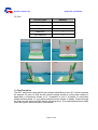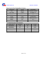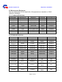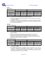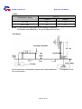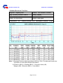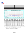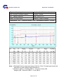
1
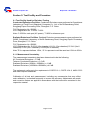
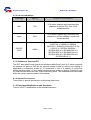
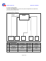
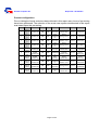
Quanta Computer Inc.
Report No.: 20130222-2
C-Tick EMC TEST REPORT
For
Laptop Computer
Brand Name:
Model NO.:
Report NO.:
Issued Date:
Issued By:
Lab Address:
Tel:
Fax:
OLPC
XO-4 HS / XO-4 / XO-4 HS Touch / XO-4 Touch
20130222-2
Feb. 22, 2013
Compliance Laboratory of Tech-Front (Shanghai) Computer Co., Ltd.
No. 68, Sanzhuang Road, Songjiang Export Processing Zone,
Shanghai, P. R. China
+86-21-3781-8168
+86-21-6774-7135
The test result relate only to the samples tested. The test report shall not be reproduced
except in full without the written approval of our laboratory. This report must not be used
to claim product endorsement by CNAS or any agency of the Government. The test
results shown in the test report are traceable to the national/international standard
through the calibration of the equipment and evaluated measurement uncertainty herein.
Page 1 of 25
Quanta Computer Inc.
Report No.: 20130222-2
Test Report Certification
Applicant:
Manufacturer:
Product:
Brand Name:
Model Number:
Tested Voltage:
Tested Date:
Quanta Computer Inc
Quanta Computer Inc
Laptop Computer
OLPC
XO-4 HS / XO-4 / XO-4 HS Touch / XO-4 Touch
240Vac, 50Hz
Jan. 09-Jan. 12, 2013
Applicable Standards:
Emission
Standard
AS/NZS
CISPR22:2009
Item
Result
Remark
Conducted (Main Port)
Pass
Meet ClassB limit
Conducted (Telecom Port)
Pass
Meet ClassB limit
Radiated
Pass
Meet ClassB limit
The above equipment has been tested by Compliance Laboratory of Tech-Front
(Shanghai) Computer Co., Ltd. , and found compliance with the requirements set forth in
the technical standards mentioned above. The result of testing in this report apply only to
the product/system, which was tested. Other similar equipment will not necessarily
produce the same resluts due to production tolerance and measurement uncertainties.
Approved By
Reviewed By
Herculus Hsu/ EMC manager:
Bill Bo/ Senior engineer
Page 2 of 25
Quanta Computer Inc.
Report No.: 20130222-2
Section 1: General Information……………………..………………………...……… 4
1.1 Introduction ………………………………………….………………………...……… 4
1.2 Test Procedure …………………..…………………….………………………….. 5
Section 2: Test Facility and Procedure……………………………….……..……. 6
2.1 Test Facility used for Emission Testing ………………………………..……. 6
2.1.1 Measurement Uncertainty …………………………………………………..……. 6
2.1.2 Lab Accreditation …………………………..…………..…………….……..….…7
2.1.3 Software to exercise EUT …………………………………………………….…7
2.1.4 Special Accessories …………………………………………….…………….….7
2.1.5 Equipment Modifications and Deviations ……………………………………...7
2.1.6 Test Configuration ………………………………………………………..……….8
- Arrangement block diagram …………………………………………..……..…. 8
- Associated equipment ………………………………………………..………... 8
- Pre-test configuration …………………………………………………..……….9
- Worst case for final testing …………………….…………….…..………. 10
2.1.7 Cable Description and Information ……………………….…………….………10
2.2 Measurement Equipment …………….…………………………………..……. 11
2.2.1 Conducted Emissions ……………………………………………………………..11
2.2.2 Radiated Emissions ………………………………………………………………11
Section 3: Electromagnetic Emissions Test………………..…………………. 12
3.1 Emission …………….………………………………………………………………. 12
3.1.1 Line Conducted Emissions Test ……………………………………………..…. 12
- Measurement Procedures Utilized for Conducted Emissions ……………. 12
- Limits …………………………………….………………………………….………. 13
- Test setup…………………………………………………………………….………. 14
- Conducted Emissions Test Data ………………………………….………. 15
3.1.2 Radiated Emissions Test ………………………………………………………… 17
- Measurement Procedures Utilized for Radiated Emissions ………………. 17
- Limits …………………………………….………………………………….………. 18
- Test setup…………………………………………………………………….………. 18
- Radiated Emissions Test Data ……………………………………….………. 19
Section 4: Test Arrangement Photos……...…………...………………………… 23
4.1 Conducted Emissions ……………………...…………………………………… 23
4.2 Radiated Emissions ………………………..………………….………………… 24
Page 3 of 25
Quanta Computer Inc.
Report No.: 20130222-2
Section 1: General Information
1.1 Introduction
Product
Laptop Computer
Trade Name
OLPC
Model Name
XO-4 HS / XO-4 / XO-4 HS Touch / XO-4 Touch
Housing Type
Plastic
Bestec
Model
AC Power Adapter
NA0241WAA
BT-AG250SDF
BU24-1203
Darfon
Model
BB0J-C
BP24-1203
AC Power Adapter
Rating
I/P: 100-240Vac
O/P: 13.5Vdc,1.85A/12Vdc,2A
AC Power Cord Type
Non-shielded AC 2pin (0.9m)
DC Power Cable Type
Non-shielded DC (1.5m) /Non-shielded DC (1.8m)
EMMC
4GB / 8GB
Memory Capacity
1GB / 2GB
CPU
Marvell
Model
7.5’’ LCD Panel
CHIMEI
Model
SUYIN
Model
FOXLINK
Model
FE03FF-317H
QMI
Model
EM113-MV
Liteon
Model
WCBN603MH
BYD
Model
CL1
STL
Model
XO-1
Camera
WLAN
Battery
Page 4 of 25
PXA2128 (1.0GHz)
PXA2128 (1.2GHz)
G075ADE-T01
CM0316-OLPC01
CM031B-SE01
Quanta Computer Inc.
Report No.: 20130222-2
I/O Port:
I/O Port Types
Quantity
Audio in port
1
Audio out port
1
USB port
2
HDMI port
1
SD Card port
1
1.2 Test Procedure
The EUT was tested using special test software called BurnIn test v6.0, which exercises
all external I/O ports as well as the internal storage media by writing and reading (if
applicable) a continuous stream of “H” characters in font 9. A pattern of continuous
stream-scrolling black “H” on a white background was written to display. Played through
the internal audio while the EMC testing was being done. The measurements were made
while the system was exercised in this manner.
Page 5 of 25
Quanta Computer Inc.
Report No.: 20130222-2
Section 2: Test Facility and Procedure
2.1 Test Facility Used for Emission Testing
Conducted Emissions Facilities: Conducted Emissions were performed at Compliance
Laboratory of Tech-Front (Shanghai) Computer Co., Ltd. of No.68 Sanzhuang Road,
Songjiang Export Processing Zone, Shanghai, P. R. China
FCC Registration No. 602285
VCCI Registration No. C-2529/ T-1836
Note: C-2529 for main port (AC power), T-1836 for telecomm port
Radiated Emissions Facilities: Radiated Emissions measurements were performed at
QSMC Compliance Laboratory of No.68 Sanzhuang Road, Songjiang Export Processing
Zone, Shanghai, P. R. China
FCC Registration No. 602285
VCCI Registration No. R-2319 (10m chamber)/ G-191 (10m chamber)/ R-3341 (3m-2
chamber)/ G-209 (3m-2 chamber)/ R-2320(3m-2 chamber)
Note:”R-”to represent bellows 1GHz, “G-”to represent could be used test 1GHz to 6GHz
2.1.1 Measurement Uncertainty
The measurement uncertainty has been determined to be the following:
AC Conducted Emissions = 3.2 dB
Telecom Conducted Emissions = 3.5 dB
Radiated Emissions (30MHz~1000MHz) = 4.1dB
Radiated Emissions (1000MHz~6000MHz) =4.6 dB
The equipment conforms to the requirement of CISPR 16-1, CISPR 16-4-2, ANSI C63.2
and other required standards.
Calibration of all test and measurement, including any accessories that may effect
such calibration, is checked frequently to ensure the accuracy. Adjustments are made
and correction factors are applied in accordance with the instructions contained in the
respective manual.
Page 6 of 25
Quanta Computer Inc.
Report No.: 20130222-2
2.1.2 Lab Accreditations
Coverage
Agency
Scope of Accreditation
USA
FCC
3/10 meter chamber and conducted test
chamber to perform FCC Part 15/18
measurements
Japan
VCCI
3/10 meter chamber and conducted test
chamber to perform radiated / conducted
measurements
CNAS
FCC 47CFR Part 15; CISPR22; AS/NZS
CISPR 22; V-3/2008.04; GB9254;
GB17625.1; EN55022; EN61000-3-2; EN
61000-3-3; CISPR24; EN55024;
IEC/EN61000-4-2; IEC/EN61000-4-3;
IEC/EN61000-4-4; IEC/EN61000-4-5;
IEC/EN61000-4-6; IEC/EN61000-4-8;
IEC/EN61000-4-11
ISO/IEC
17025
2.1.3 Software to Exercise EUT
The EUT was tested using special test software called BurnIn test v6.0, which exercises
all external I/O ports as well as the internal storage media by writing and reading (if
applicable) a continuous stream of “H” characters in font 9. A pattern of continuous
stream-scrolling black “H” on a white background was written to display. Played through
the internal audio while the EMC testing was being done. The measurements were made
while the system was exercised in this manner.
2.1.4 Special Accessories
There were no special accessories used during these tests.
2.1.5 Equipment Modifications and Deviations
There is no EUT modification or test standard deviation.
Page 7 of 25
Quanta Computer Inc.
Report No.: 20130222-2
2.1.6 Test Configuration
The EUT was configured as a worst case system configuration as a result from
pre-testing as described below:
Arrangement Block Diagram
Adapter
Headphone
&Microphone
1
EUT
USB HDD
2
SD Card
3
HDMI
Monitor
4
USB
Mouse
5
Associated Equipments
No.
Interference
Equipment
Brand
Model
1
Audio in & out port
Mic & Headphone
Philips
SHM3300
2
USB port
HDD
Seagate
5VCA0X2F
3
SD Card port
SD Card
Kingston
4GB
4
HDMI port
Monitor
DELL
2709Wb
5
USB port
Mouse
Logitech
M-BP82
Page 8 of 25
Quanta Computer Inc.
Report No.: 20130222-2
Pre-test configuration
Prior to taking the formal emissions data collected in this report many hours of pre-testing
have been performed. The selection of the worst case system documented in this report
was based upon this pre-testing.
Mode
1
2
3
4
5
6
7
8
9
10
CPU
Marvell
PXA2128
(1.0GHz)
Marvell
PXA2128
(1.2GHz)
Marvell
PXA2128
(1.0GHz)
Marvell
PXA2128
(1.2GHz)
Marvell
PXA2128
(1.0GHz)
Marvell
PXA2128
(1.0Hz)
Marvell
PXA2128
(1.0GHz)
Marvell
PXA2128
(1.2GHz)
Marvell
PXA2128
(1.0GHz)
Marvell
PXA2128
(1.2GHz)
LCD Panel
Memory EMMC
WLAN
Camera
Battery
Adapter
QMI
EM113-MV
SUYIN
CM031B-SE01
BYD CL1
Bestec
NA0241WAA
CHIMEI
G075ADE-T01
1GB
4GB
CHIMEI
G075ADE-T01
2GB
8GB
CHIMEI
G075ADE-T01
2GB
4GB
CHIMEI
G075ADE-T01
1GB
4GB
CHIMEI
G075ADE-T01
2GB
8GB
QMI
EM113-MV
SUYIN
CM031B-SE01
BYD CL1
Bastec
BT-AG250SDF
CHIMEI
G075ADE-T01
1GB
8GB
Liteon
WCBN603M
H
FOXLINK
FE03FF-317H
BYD CL1
Darfon
BU24-1203
CHIMEI
G075ADE-T01
1GB
4GB
QMI
EM113-MV
SUYIN
CM031B-SE01
STL XO-1
Darfon
BP24-1203
CHIMEI
G075ADE-T01
1GB
8GB
Liteon
WCBN603M
H
FOXLINK
FE03FF-317H
BYD CL1
Bastec
NA0241WAA
CHIMEI
G075ADE-T01
1GB
4GB
CHIMEI
G075ADE-T01
2GB
4GB
Liteon
SUYIN
Bastec
WCBN603M CM0316-OLPC0 BYD CL1
BT-AG250SDF
H
1
QMI
EM113-MV
FOXLINK
FE03FF-317H
STL XO-1
Darfon
BU24-1203
Liteon
SUYIN
WCBN603M CM0316-OLPC0 STL XO-1 Darfon BB0J-C
H
1
SUYIN
QMI
CM0316-OLPC0 STL XO-1
EM113-MV
1
Liteon
SUYIN
WCBN603M
BYD CL1
CM031B-SE01
H
Page 9 of 25
Bastec
NA0241WAA
Darfon
BP24-1203
Quanta Computer Inc.
Report No.: 20130222-2
Worst Case for Final Testing (Mode 2 Chosen)
Component
Vendor
Part Number
CPU
Marvell
PXA2128 (1.2GHz)
LCD Panel
CHIMEI
G075ADE-T01
Memory
Hynix
2GB
EMMC
Toshiba
8GB
WLAN
Liteon
WCBN603MH
Camera
SUYIN
CM0316-OLPC01
Battery
BYD
CL1
Power Adapter
Bestec
BT-AG250SDF
2.1.7 Cable Description and Information
Cable Type
Shielded
Ferrite
Length
HDMI Monitor
Yes
No
1.50m
USB Mouse
No
No
1.80m
USB 2.0 HDD
Yes
No
1.50m
Audio In
No
No
1.80m
Audio Out
No
No
1.80m
Page 10 of 25
Quanta Computer Inc.
Report No.: 20130222-2
2.2 Measurement Equipment
N/A is an abbreviation for Not Applicable. All equipments are traceable to CNAS
calibration standards.
2.2.1 Conducted Emissions
Description
Manufacturer
Model No.
Serial No.
Calibrated Until
Test Receiver
Rohde & Schwarz
ESCI
100167
5/18/2013
LISN
Schwarz beck
NSLK8127
8127433
5/18/2013
LISN
Schwarz beck
NSLK8128
8128229
5/18/2013
TLISN
TeseQ
CDN ST08A
30189
5/18/2013
TLISN
TeseQ
ISN ST800
29453
5/18/2013
TLISN
FCC
FCC-TLISN-T4-02
20581
5/18/2013
TLISN
FCC
FCC-TLISN-T8-02
20445
5/18/2013
Probe
FCC
F-33-4
57
5/18/2013
Probe
FCC
F35
507
5/18/2013
2.2.2 Radiated Emissions
Description
Manufacturer
Model No.
Serial No.
Calibrated Until
Test Receiver
Rohde & Schwarz
ESCI
100166
5/18/2013
Test Receiver
Rohde & Schwarz
ESIB26
100307
5/18/2013
Spectrum
Analyzer
Agilent
E7405A
MY42000093
5/18/2013
Bilog Antenna
Schwarz beck
VULB9168
9168-195
7/01/2013
Bilog Antenna
Schwarz beck
VULB9168
9168-198
7/01/2013
Horn Antenna
Schwarz beck
BBHA 9120D
409
5/03/2013
Preamplifier
Agilent
8447D
2944A10848
5/18/2013
Preamplifier
Agilent
8447D
2944A10847
5/18/2013
Preamplifier
Agilent
8449B
3008A02145
5/18/2013
Preamplifier
Agilent
8449B
3008A02146
5/18/2013
Software
ADT
ADT_Radiated_V7
N/A
N/A
Antenna Mast
Inn-co
MA4000
MA4000/101/9770
405/L
N/A
Antenna Mast
Inn-co
MA4000
MA4000/104/9770
405/L
N/A
Turn Table
Inn-co
DT3000-1T-C
DT3000-1T-C/22
N/A
Controller
Inn-co
CO2000
CO2000/218/9770
405/L
N/A
Page 11 of 25
Quanta Computer Inc.
Report No.: 20130222-2
Section3: Electromagnetic Emissions Test
3.1 Emission
3.1.1 Line Conducted Emissions Test
- Measurement Procedures Utilized for Conducted Emissions
The EUT was set up as per the test configuration to simulate typical usage per the user’s
manual. When the EUT is a tabletop system, a wooden table with a height of 0.8 meters
is used and is placed on the ground plane as per AS/NZS CISPR22.
Associated equipment, if needed, was placed as per AS/NZS CISPR22.
All I/O cables were positioned to simulate typical actual usage as per AS/NZS CISPR22.
The test equipment EUT installed received AC power through a Line Impedance
Stabilization Network (LISN), which supplied power source and was grounded to the
ground plane.
All associated equipment received power from a second LISN.
For conducted emission test on telecommunication ports, a telecommunication port is
connected by its signal cable to an impedance stabilization network (ISN). During the
testing, the LAN utilization is in excess of 10 % and sustains that level for a minimum of
250 ms. the traffic rate is monitored by the program of Net Speed.
The EUT test program was started. Emissions were measured on each current carrying
line of the EUT using an EMI Test Receiver connected to the LISN powering the EUT.
The Receiver scanned from 150 KHz to 30MHz for emissions in each of the test modes.
During the above scans under battery charging mode, the emissions were maximized by
cable manipulation.
The EUT configuration and cable configuration of the above highest emission level were
recorded for reference of the final test.
Page 12 of 25
Quanta Computer Inc.
Report No.: 20130222-2
- Limits
For AC Power
Frequency (MHz)
Class A (dBuV)
Class B (dBuV)
Quasi-peak
Average
Quasi-peak
Average
0.15 - 0.5
79
66
66 - 56
56 - 46
0.50 - 5.0
73
60
56
46
5.0 - 30.0
73
60
60
50
Note:1)The lower limit shall apply at the transition frequencies.
2)The limit decreases in line with the logarithm of the frequency in the range of
0.15MHz to 0.50MHz.
3)All emanations from a class A/B digital device or system, including any network
of conductors and apparatus connected thereto, shall not exceed the level of
field strengths specified above.
For ISN
For Class A Equipment
FREQUENCY (MHz)
Voltage Limit (dBuV)
Current Limit (dBuA)
Quasi-peak
Average
Quasi-peak
Average
0.15 ~ 0.5
97 ~ 87
84 ~ 74
53 ~ 43
40 ~ 30
0.5 ~ 30.0
87
74
43
30
Note:1)The limits decrease linearly with the logarithm of the frequency in the range 0.15
MHz to 0.5MHz.
2)The current and voltage disturbance limits are derived for use with an
impedance stabilization network (ISN) which presents a common mode
(asymmetric mode) impedance of 150Ω to the telecommunication port under
test(conversion factor is 20㏒10150=44dB).
For Class B Equipment
FREQUENCY (MHz)
Voltage Limit (dBuV)
Current Limit (dBuA)
Quasi-peak
Average
Quasi-peak
Average
0.15 - 0.5
84 ~ 74
74 ~ 64
40 ~ 30
30 ~ 20
0.5 - 30.0
74
64
30
20
Note: 1)The limits decrease linearly with the logarithm of the frequency in the range
0.15 MHz to 0.5MHz.
2)The current and voltage disturbance limits are derived for use with an
impedance stabilization network(ISN) which presents a common mode
(asymmetric mode) impedance of 150Ω to the telecommunication port under
test (conversion factor is 20㏒10150=44dB)
Page 13 of 25
Quanta Computer Inc.
Report No.: 20130222-2
- Test Setup
For AC power setup as below
For ISN setup as below
For the actual test configuration, please refer to the related item–Photographs of the Test
Configuration.
Page 14 of 25
Quanta Computer Inc.
Report No.: 20130222-2
- Conducted Emissions Test Data
Engineer : Xingming zhao
Location : Conduction Room
Limit : AS/NZS CISPR22 Class B
Probe : Line 1
EUT : Laptop Computer
Date : 2013-01-09
Power : AC 240V/50Hz
Detector : Quasi peak and Average
Temperature. : 22℃ Relative Humidity.: 54% Atmospheric Pressure.: 101kpa
Note: 1) Conducted Emissions data was taken at 240Vac, 50Hz. This data was found to
be equivalent or lower than the data listed above
2) Emission (dBuV) = Reading (dBuV) + Correction factor (dB)
Margins (dB) = Emission (dBuV) – Limit (dBuV)
Page 15 of 25
Quanta Computer Inc.
Report No.: 20130222-2
Engineer : Xingming zhao
Location : Conduction Room
Limit : AS/NZS CISPR22 Class B
Probe : Line 2
EUT : Laptop Computer
Date : 2013-01-09
Power : AC 240V/50Hz
Detector : Quasi peak and Average
Temperature. : 22℃ Relative Humidity.: 54% Atmospheric Pressure.: 101kpa
Note: 1) Conducted Emissions data was taken at 240Vac, 50Hz. This data was found to
be equivalent or lower than the data listed above
2) Emission (dBuV) = Reading (dBuV) + Correction factor (dB)
Margins (dB) = Emission (dBuV) – Limit (dBuV)
Page 16 of 25
Quanta Computer Inc.
Report No.: 20130222-2
3.1.2 Radiated Emissions Test
- Measurement Procedures Utilized for Radiated Emissions
The equipment was set up as per the test configuration to simulate typical usage per the
user’s manual. When the EUT is a tabletop system, a wooden turntable with a height of
0.8 meters is used which is placed on the ground plane.
Associated equipment, if needed, was placed as per AS/NZS CISPR22.
All I/O cables were positioned to simulate typical usage as per AS/NZS CISPR22.
The EUT received AC power source, from the outlet socket under the turntable. All
associated equipment received power from another socket under the turntable.
Mains cables, telephone lines or other connections to auxiliary equipment located
outside the test are shall drape to the floor. No extension cords shall be used to mains
receptacle.
The antenna was placed at 10 meter away from the EUT as stated in AS/NZS CISPR22.
The antenna connected to the Receiver via a cable and at times a pre-amplifier would be
used.
The receiver scanned from 30MHz to 1000MHz. The EUT test program was started.
Emissions were scanned under battery charging mode and measured rotating the EUT
to 360 degrees and positioning the antenna 1 to 4 meters above the ground plane, in
both vertical and horizontal polarization, to maximize the emission reading level.
The test mode(s) described in Item 2.1.6 were scanned during the preliminary test:
After the preliminary scan, we found the test mode described in Item 2.1.6 producing the
highest emission level.
The EUT and cable configuration, antenna position, polarization and turntable position of
the above highest emission level were recorded for the final test.
Page 17 of 25
Quanta Computer Inc.
Report No.: 20130222-2
-Limits
FREQUENCY (MHz)
dBuV/m
Class A
Class B
30 ~ 230
40
30
230 ~ 1000
47
37
NOTE: 1) The lower limit shall apply at the transition frequencies.
2) Emission level (dBuV/m) = 20 log10 Emission level (uV/m).
-Test Setup
For the actual test configuration, please refer to the related item – Photographs of the
Test Configuration.
Page 18 of 25
Quanta Computer Inc.
Report No.: 20130222-2
- Radiated Emissions Test Data
Engineer : Xingming zhao
Location : 10m Radiation Chamber
Limit : AS/NZS CISPR22 Class B
Polarity : Vertical
EUT : Laptop Computer
Date : 2013-01-10
Power : AC 240V/50Hz
Detector: Quasi peak
Temperature. : 18℃ Relative Humidity.: 56% Atmospheric Pressure.: 101kpa
Note: 1).Radiated Emissions data was taken at 240Vac, 50Hz. This data was found to be
equivalent or lower than the data listed above.
2).Emission (dBuV) = Reading (dBuV) + Correction factor (dB)
Margins (dB) = Emission (dBuV) – Limit (dBuV)
Page 19 of 25
Quanta Computer Inc.
Report No.: 20130222-2
Engineer : Xingming zhao
Location : 10m Radiation Chamber
Limit : AS/NZS CISPR22 Class B
Polarity: Horizontal
EUT : Laptop Computer
Date : 2013-01-10
Power : AC 240V/50Hz
Detector: Quasi peak
Temperature. : 18℃ Relative Humidity.: 56% Atmospheric Pressure.: 101kpa
Note: 1).Radiated Emissions data was taken at 240Vac, 50Hz. This data was found to be
equivalent or lower than the data listed above.
2).Emission (dBuV) = Reading (dBuV) + Correction factor (dB)
Margins (dB) = Emission (dBuV) – Limit (dBuV)
Page 20 of 25
Quanta Computer Inc.
Report No.: 20130222-2
Engineer : Xingming zhao
Location : 3m-2 Radiation Chamber
Limit : AS/NZS CISPR22 Class B
Polarity : Vertical
EUT : Laptop Computer
Date : 2013-01-12
Power : AC 240V/50Hz
Detector : Peak & Average
Temperature. : 20℃
Relative Humidity.: 60% Atmospheric Pressure.: 101kpa
Note: 1).Radiated Emissions data was taken at 240Vac, 50Hz. This data was found to be
equivalent or lower than the data listed above.
2).Emission (dBuV) = Reading (dBuV) + Correction factor (dB)
Margins (dB) = Emission (dBuV) – Limit (dBuV)
Page 21 of 25
Quanta Computer Inc.
Report No.: 20130222-2
Engineer : Xingming zhao
Location : 3m-2 Radiation Chamber
Limit : AS/NZS CISPR22 Class B
Polarity : Horizontal
EUT : Laptop Computer
Date : 2013-01-12
Power : AC 240V/50Hz
Detector: Peak & Average
Temperature. : 20℃
Relative Humidity.: 60% Atmospheric Pressure.: 101kpa
Note: 1).Radiated Emissions data was taken at 240Vac, 50Hz. This data was found to be
equivalent or lower than the data listed above.
2).Emission (dBuV) = Reading (dBuV) + Correction factor (dB)
Margins (dB) = Emission (dBuV) – Limit (dBuV)
Page 22 of 25
Quanta Computer Inc.
Report No.: 20130222-2
Section 4: Test Arrangement Photos
4.1 Conducted Emissions (AC Power)
Page 23 of 25
Quanta Computer Inc.
Report No.: 20130222-2
4.2 Radiated Emissions
Page 24 of 25
Quanta Computer Inc.
Report No.: 20130222-2
Page 25 of 25