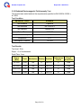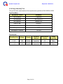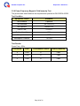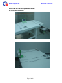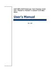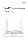
1
Quanta Computer Inc.
Report No.: 20070712-1
EMC COMPLIANCE TEST REPORT
REPORT NO.:
20070712-1
PRODUCT:
Laptop
BRAND NAME: OLPC
MODEL NO.:
XO-1, XO*** (* means any character or blank)
ISSUED DATE: Jul. 12, 2007
ISSUED BY:
QSMC Compliance Center
LAB ADDRESS: No. 68, Sanzhuang Road, Songjiang Export
Processing Zone, Shanghai, P. R. China
COMPLIANCE STANDARDS:
FCC 47CFR Part 15, Subpart B, Class B; ANSI C63.4:2003
ICES-003
CISPR 22:1993+A1:1995+A2:1996, Class B
CISPR 22: 2006
CISPR 24:1997+A1:2001+A2:2002
AS/NZS CISPR 22:2004, Class B
V-3/2006.04
V-4/2006.04
CNS13438
GB9254
GB17625.1
ETSI EN 301 489-1 v1.6.1: 2005
ETSI EN 301 489-17 v1.2.1:2002
EN 61000-3-2:2006
EN 61000-3-3:1995+A1:2001+A2:2006
EN 55024:1998+A1:2001+A2:2003
EN 61000-4-2:2001
EN 61000-4-3:2002+A1:2002
EN 61000-4-4:2004
EN 61000-4-5:2001
EN 61000-4-6:2003+A1:2004
EN 61000-4-8:2001
EN 61000-4-11:2004
EN 55022:1998+A1:2000+A2:2003, Class B
EN 55022:2006, Class B
Page 1 of 32
Quanta Computer Inc.
Report No.: 20070712-1
Section 1: General Information
1.1 Introduction ……………………………………………….………………………...……… 5
1.2 Test Procedure …………………………..…………………….………………………….. 7
Section 2: Test Facility And Procedure
2.1 Test Facility used for Emission Testing …………………………………………..……. 8
2.1.1 Measurement Uncertainty …………………………………………………..……. 8
2.1.2 Lab Accreditation …………………………..…………..…………………..………9
2.1.3 Software to exercise EUT …………………………………………………………9
2.1.4 Special Accessories …………………………………………….………………….9
2.1.5 Equipment Modifications and Deviations ……………………………………….9
2.1.6 Test Configuration ………………………………………………………..………. 10
- Arrangement block diagram …………………………………………..………. 10
- Associated equipment ………………………………………………..………. 10
- Pre-test configuration …………………………………………………..……….11
- Worst case for final testing …………………………………………..………. 11
2.1.7 Cable Description and Information ………………………….……………………11
2.2 Measurement Equipment ………………….……………………………………..……. 12
2.2.1 Conducted Emissions ……………………………………………………………..12
2.2.2 Radiated Emissions ………………………………………………………………12
2.2.3 Power Harmonic / Flickers ……………………………………………..…………13
2.2.4 Electrostatic Discharge (ESD) Immunity ……………………………..……….. 13
2.2.5 Radiated Electromagnetic Field Immunity ……………………………..………. 13
2.2.6 Fast Transient / Burst Immunity …………………………………………………14
2.2.7 Surge Immunity …………………………………………………………..………. 14
2.2.8 Conducted Disturbance / Induced Radio-Frequency Field Immunity ………. 14
2.2.9 Power Frequency Magnetic Field Immunity ……………………….…………… 15
2.2.10 Voltage Dips / Short Interruptions and Interruptions ………………………… 15
Page 2 of 32
Quanta Computer Inc.
Report No.: 20070712-1
Section 3: Electromagnetic Emissions Test
3.1 Emission ………………….………………………………………………………………. 16
3.1.1 Line Conducted Emissions Test ……………………………………………..…. 16
- Measurement Procedures Utilized for Conducted Emissions ……………. 16
- Conducted Emissions Test Data …………………………………….………. 16
3.1.2 Radiated Emissions Test ………………………………………………………… 19
- Measurement Procedures Utilized for Radiated Emissions ………………. 19
- Radiated Emissions Test Data ……………………………………….………. 19
3.1.3 Power Harmonics Measurement ……………………………………….………. 23
3.1.4 Power Voltage Fluctuation / Flicker Measurement …………………….……… 23
3.2 Electromagnetic Immunity Report ………………………………….......……………… 24
3.2.1 Electrostatic Discharge (ESD) Immunity Test …………….…………………… 24
3.2.2 Radiated Electromagnetic Field Immunity Test ………….…….……………… 25
3.2.3 Fast Transient/Burst Immunity Test ………………...…...……………………… 26
3.2.4 Surge Immunity Test ………...…………………………………………………… 27
3.2.5 Conducted Disturbance / Induced Radio-Frequency Field Immunity Test …. 28
3.2.6 Power Frequency Magnetic Field Immunity Test ……………...........………… 29
3.2.7 Voltage Dips / Short Interruptions and Interruptions Test ………….………… 30
Section 4: Test Arrangement Photos
4.1 Conducted Emissions …………………………...……………………………………… 31
4.2 Radiated Emissions ……………………………..…………………….………………… 32
Page 3 of 32
Quanta Computer Inc.
Report No.: 20070712-1
Applicant:
OLPC
Manufacturer:
Quanta Computer Inc.
Product:
Laptop
Brand Name:
OLPC
Model Number: XO-1, XO*** (* means any character or blank)
Test Date:
Jun. 19 - Jul. 4, 2007
COMPLIANCE STANDARDS:
FCC 47CFR Part 15, Subpart B, Class B; ANSI C63.4:2003
ICES-003
CISPR 22:1993+A1:1995+A2:1996, Class B
CISPR 22: 2006
CISPR 24:1997+A1:2001+A2:2002
AS/NZS CISPR 22:2004, Class B
V-3/2006.04
V-4/2006.04
CNS13438
GB9254
GB17625.1
ETSI EN 301 489-1 v1.6.1: 2005
ETSI EN 301 489-17 v1.2.1:2002
EN 61000-3-2:2006
EN 61000-3-3:1995+A1:2001+A2:2006
EN 55024:1998+A1:2001+A2:2003
EN 61000-4-2:2001
EN 61000-4-3:2002+A1:2002
EN 61000-4-4:2004
EN 61000-4-5:2001
EN 61000-4-6:2003+A1:2004
EN 61000-4-8:2001
EN 61000-4-11:2004
EN 55022:1998+A1:2000+A2:2003, Class B
EN 55022:2006, Class B
Approved By
Reviewed By
…………………………………………………………………………………………….
Herculus Hsu
Joyce Kuo
Page 4 of 32
Quanta Computer Inc.
Report No.: 20070712-1
Section 1: General Information
1.1 Introduction
Product
Laptop
Trade Name
OLPC
Model Name
XO-1, XO*** (* means any character or blank)
Housing Type
Plastic
AC Power Adapter
Delta
Model
PIE
Model
Lite-On
Model
ADP-17FB AA
ADP-17FB BA
ADP-17FB CA
ADP-17FB DA
AD5950 A LF
AD5952 A LF
AD5953 A LF
AD5959 A LF
PA-1150-05Q1
PA-1150-05Q2
PA-1150-05Q3
PA-1150-05Q4
AC Power Adapter Rating
I/P: 100-240VAC
O/P: 12Vdc, 1250mA
AC Power Core Type
Non-shielded AC 2-pin (1.8m)
DC Power Cable Type
Non-shielded DC (1.8m) with one ferrite core
CPU
AMD
Memory Capacity
256MB
RAM
Model
LX700
PSC
Model
A3S12D40ETP-G6 X 4
Hynix
Model
HY5DU121622CTP-J X 4
Samsung Model
K4H511638D-UCCC X 4
Model
Model
HYB25DC512160BE-5 X 4
LCD
Qimoda
CHILIN
NAND Flash
ST
Model
NAND08GW3B2AN6E (1GB)
Hynix
Model
HY27UG088G5M-TPCB (1GB)
Camera
LS075AT011
Samsung Model
K9K8G08U0A-PCB0 (1GB)
Lite-On
Model
06P052
Suyin
Model
CM0316-OLPC01
Page 5 of 32
Quanta Computer Inc.
VRAM
Battery
Wireless LAN
Report No.: 20070712-1
UMS
Model
M12S16161A-7TG
ETI
Model
EM6A6165TS-7G
ISSI
Model
IS42R16100C1-7TL
GPI
Model
NTA2488
BYD
Model
600000049
QMI
Model
US101
I/O Port:
IO Port Types
Quantity
USB port
3
Audio in port
1
Audio out port
1
SD Card
1
Page 6 of 32
Quanta Computer Inc.
Report No.: 20070712-1
1.2 Test Procedure
The EUT was tested using special test software called H patterns, which exercises all
external I/O ports as well as the internal storage media by writing and reading (if
applicable) a continuous stream of “H” characters. A pattern of continuous
stream-scrolling black “H” on a white background was written to display. To exercise the
optical drive, a CD was put into the optical drive and played through the internal audio
while the EMC testing was being done. The measurements were made while the system
was exercised in this manner.
Page 7 of 32
Quanta Computer Inc.
Report No.: 20070712-1
Section 2: Test Facility and Procedure
2.1 Test Facility Used for Emission Testing
Conducted Emissions Facilities: Conducted Emissions were performed at QSMC
Compliance Center of No.68 Sanzhuang Road, Songjiang Export Processing Zone,
Shanghai, P. R. China
FCC Registration No. 602285
VCCI Registration No. C-2529
Radiated Emissions Facilities: Radiated Emissions measurements were performed at
QSMC Compliance Center of No.68 Sanzhuang Road, Songjiang Export Processing
Zone, Shanghai, P. R. China
FCC Registration No. 602285
VCCI Registration No. R-2319
2.1.1 Measurement Uncertainty
The measurement uncertainty has been determined to be the following:
Conducted Emissions = ± 3.2 dB
Radiated Emissions = ± 3.6 dB
The equipment conforms to the requirement of CISPR 16-1, CISPR 16-4-2, ANSI C63.2
and other required standards.
Calibration of all test and measurement, including any accessories that may effect
such calibration, is checked frequently to ensure the accuracy. Adjustments are made
and correction factors are applied in accordance with the instructions contained in the
respective manual.
Page 8 of 32
Quanta Computer Inc.
Report No.: 20070712-1
2.1.2 Lab Accreditations
Coverage
USA
Japan
Agency
Scope of Accreditation
FCC
3/10 meter chamber and
conducted test chamber to
perform FCC Part 15/18
measurements
VCCI
3/10 meter chamber and
conducted test chamber to
perform radiated / conducted
measurements
Logo
602285
R-2320 / 2319
C-2529
ISO/IEC
17025
CNAS
FCC 47CFR Part 15;
CISPR22; AS/NZS CISPR 22;
V-3/2006.04; V-4/2006.04;
CNS13438; GB9254;
GB17625.1; EN55022;
EN61000-3-2; EN 61000-3-3;
CISPR24; EN55024;
EN61000-4-2; EN61000-4-3;
EN61000-4-4; EN61000-4-5;
EN61000-4-6; EN61000-4-8;
EN61000-4-11
2.1.3 Software to Exercise EUT
The EUT was tested using special test software called H patterns, which exercises all
external I/O ports as well as the internal storage media by writing and reading (if
applicable) a continuous stream of “H” characters. A pattern of continuous
stream-scrolling black “H” on a white background was written to display. To exercise the
optical drive, a disk was put into the drive tray and played through the internal audio
while the EMC testing was being done. The measurements were made while the system
was exercised in this manner.
2.1.4 Special Accessories
There were no special accessories used during these tests.
2.1.5 Equipment Modifications and Deviations
There is no EUT modification or test standard deviation.
Page 9 of 32
Quanta Computer Inc.
Report No.: 20070712-1
2.1.6 Test Configuration
The EUT was configured as a worst case system configuration as a result from
pre-testing as described below:
Arrangement Block Diagram
SD Card
5
EUT
USB
Mouse
1
Headphone
&Microphone
4
USB
Mouse
2
USB
Mouse
3
Associated Equipments
Description
Model
1
Microsoft mouse
X08-71118
2
Microsoft mouse
X08-71118
3
Microsoft mouse
X08-71118
4
Philips headphone/mic
SBC HM450
5
SD card Transcend
1GB
Page 10 of 32
Quanta Computer Inc.
Report No.: 20070712-1
Pre-test configuration
Prior to taking the formal emissions data collected in this report many hours of
pre-testing have been performed. The selection of the worst case system documented in
this report was based upon this pre-testing.
Mode
1
2
3
4
5
6
7
8
9
10
11
12
CPU
AMD
LX700
AMD
LX700
AMD
LX700
AMD
LX700
AMD
LX700
AMD
LX700
AMD
LX700
AMD
LX700
AMD
LX700
AMD
LX700
AMD
LX700
AMD
LX700
LCD Panel Memory
Camera
CHILIN
Lite-On
256MB
LS075AT011
06P052
CHILIN
Lite-On
256MB
LS075AT011
06P052
CHILIN
Lite-On
256MB
LS075AT011
06P052
CHILIN
Lite-On
256MB
LS075AT011
06P052
CHILIN
Suyin
256MB
LS075AT011
CM0316-OLPC0
CHILIN
Suyin
256MB
LS075AT011
CM0316-OLPC0
CHILIN
Suyin
256MB
LS075AT011
CM0316-OLPC0
CHILIN
Suyin
256MB
LS075AT011
CM0316-OLPC0
CHILIN
Suyin
256MB
LS075AT011
CM0316-OLPC01
CHILIN
Suyin
256MB
LS075AT011
CM0316-OLPC01
CHILIN
Suyin
256MB
LS075AT011
CM0316-OLPC01
CHILIN
Suyin
256MB
LS075AT011
CM0316-OLPC01
WLAN
QMI
US101
QMI
US101
QMI
US101
QMI
US101
QMI
US101
QMI
US101
QMI
US101
QMI
US101
QMI
US101
QMI
US101
QMI
US101
QMI
US101
NAND Flash
VRAM
1GB
2MB
1GB
2MB
1GB
2MB
1GB
2MB
1GB
2MB
1GB
2MB
1GB
2MB
1GB
2MB
1GB
2MB
1GB
2MB
1GB
2MB
1GB
2MB
Battery
GPI
NTA2488
GPI
NTA2488
BYD
600000049
BYD
600000049
GPI
NTA2488
GPI
NTA2488
BYD
600000049
BYD
600000049
GPI
NTA2488
GPI
NTA2488
BYD
600000049
BYD
600000049
Adapter
Lite-On
PA-1150-05Q1
Lite-On
PA-1150-05Q2
Lite-On
PA-1150-05Q3
Lite-On
PA-1150-05Q4
Delta
ADP-17FB AA
Delta
ADP-17FB BA
Delta
ADP-17FB CA
Delta
ADP-17FB DA
PIE
AD5950 A LF
PIE
AD5952 A LF
PIE
AD5953 A LF
PIE
AD5959 A LF
Worse Case for Final Testing (mode 11 chosen)
Component
Vendor
Part Number
CPU
AMD
LX700
LCD Module
CHILIN
LS075AT011
Power Adapter
PIE
AD5953 A LF
Battery
BYD
600000049
Camera
Suyin
CM0316-OLPC01
Wireless LAN
QMI
US101
RAM
Hynix
256MB
NAND Flash
Hynix
1GB
VRAM
UMS
2MB
2.1.7 Cable Description and Information
Cable Type
Shielded
Ferrite
USB cable
Yes
No
Multimedia Headset
Yes
No
Page 11 of 32
Quanta Computer Inc.
Report No.: 20070712-1
2.2 Measurement Equipment
N/A is an abbreviation for Not Applicable. All equipments are traceable to CNAS
calibration standards.
2.2.1 Conducted Emissions
Description
Manufacturer
Model No.
Serial No.
Calibrated Until
Test Receiver
Rohde & Schwarz
ESC1
100167
5/24/2008
LISN
Schwarzbeck
NSLK8127
8127433
5/24/2008
LISN
Schwarzbeck
NSLK8128
8128229
5/24/2008
TLISN
FCC
FCC-TLISN-T2
20217
5/24/2008
TLISN
FCC
FCC-TLISN-T4
20218
5/24/2008
Software
ADT
ADT_Cond_V7.3 .4
N/A
N/A
2.2.2 Radiated Emissions
Description
Manufacturer
Model No.
Serial No.
Calibrated Until
Test Receiver
Rohde & Schwarz
ESCI
100166
5/24/2008
Test Receiver
Rohde & Schwarz
ESIB26
100307
5/24/2008
Bilog Antenna
Schwarzbeck
VULB9168
9168-198
6/1/2008
Bilog Antenna
Schwarzbeck
VULB9168
9168-195
6/1/2008
Preamplifier
Agilent
8447D
2944A10848
5/24/2008
Preamplifier
Agilent
8447D
2944A10847
5/24/2008
Preamplifier
Agilent
8449B
3008A02145
5/24/2008
Software
ADT
ADT_Radiated_V7
N/A
N/A
Antenna Mast
Innco
MA4000
MA4000/101/9
770405/L
N/A
Antenna Mast
Innco
MA4000
MA4000/104/9
770405/L
N/A
Turn Table
Innco
DT3000-1T-C
DT3000-1T-C/2
2
N/A
Controller
Innco
CO2000
CO2000/218/9
770405/L
N/A
Page 12 of 32
Quanta Computer Inc.
Report No.: 20070712-1
2.2.3 Power Harmonics and Voltage Fluctuation/Flicker
Description
Manufacturer
Model No.
Serial No.
Calibrated Until
AC Power
Source
EMTest
ACS 500
V0523100459
5/24/2008
Harmonics &
Flicker Analyzer
EMTest
DPA 500
72224
5/24/2008
Software
EMTest
EMTest software
N/A
N/A
2.2.4 Electrostatic Discharge (ESD) Immunity
Description
Manufacturer
Model No.
Serial No.
Calibrated Until
ESD Simulator
EMTest
ESD 30C
V0523100460
6/1/2008
ESD Simulator
Noiseken
ESS-2002
ESS0423758
5/30/2008
ESD Simulator
Keytek
MZ-15/EC
0506331
5/30/2008
2.2.5 Radiated Electromagnetic Field Immunity
Description
Manufacturer
Model No.
Serial No.
Calibrated Until
Amplifier
Amplifier Research
150W1000
312368
N/A
Amplifier
Amplifier Research
60S1G3(M1)
312416
N/A
Antenna
Amplifier Research
AT5080
312113
N/A
Antenna Tripod
Evergo
TP1000A
N/A
N/A
IF4000A
310906
N/A
Field Monitoring Amplifier Research
Power Meter
Boonton
4232A
142402
5/24/2008
Power Meter
Boonton
51011EMC
33838/33839
5/24/2008
Accessories
Amplifier Research
DC6180A
312192
N/A
Accessories
Amplifier Research
DC7144A
311989
N/A
Controller
Amplifier Research
SC1000M1
312477
N/A
Signal
Generator
Rohde& Schwarz
SML03
102270
5/24/2008
Page 13 of 32
Quanta Computer Inc.
Report No.: 20070712-1
2.2.6 Fast Transient/Burst Immunity
Description
Manufacturer
Model No.
Serial No.
Calibrated Until
EFT Generator
EMTest
EFT500
V0523100450
5/24/2008
CA EFT kit
EMTest
KW50 / KW1000
N/A
N/A
EMTest
Software
EMTest Software
N/A
N/A
2.2.7 Surge Immunity
Description
Manufacturer
Model No.
Serial No.
Calibrated Until
Telecom surge
generator
EMTest
TSS 500 M10
V0523100456
5/24/2008
Impulse
Generator
EMTest
VCS 500 M10
V0523100451
5/24/2008
2.2.8 Conducted Disturbance/Induced Radio-Frequency Field Immunity
Description
Manufacturer
Model No.
Serial No.
Calibrated Until
Continuous
Wave Simulator
EMTest
CWS 500C
V053100457
5/24/2008
Attenuator
EMTest
ATT 6/75
1104-13
N/A
CDN
EMTest
CDN-M2/M3
0705-02
N/A
CDN
EMTest
CDN-T2
0705-01
N/A
CDN
EMTest
Adapter T2-RJ11
N/A
N/A
CDN
EMTest
CDN-T4
0705-01
N/A
CDN
EMTest
CDN-T8-RJ45
N/A
N/A
EM Clamp
EMTest
EM Clamp
35737
N/A
Basic calibration
kit
EMTest
CWS-CAL
N/A
N/A
CA M2/M3/AF3
EMTest
CA M2/M3/AF3
N/A
N/A
calibration kit
EMTest
CA T2/AF2
N/A
N/A
calibration kit
EMTest
CA T4/AF4/M4
N/A
N/A
Built-in power
monitor
EMTest
PM402
0705-01
N/A
calibration kit
EMTest
CA EM
276
N/A
Operation
system for
CWS500C
EMTest
Win lcd l2
0705-01
N/A
Page 14 of 32
Quanta Computer Inc.
Report No.: 20070712-1
Capacitive
coupling clamp
EMTest
HFK (-4)
0605-08
N/A
CDN
EMTest
CDN-M1
N/A
N/A
CDN
EMTest
CDN-AF4
0705-01
N/A
calibration kit
EMTest
CAA M2/M3
0263
N/A
calibration kit
EMTest
CA-M1
N/A
N/A
2.2.9 Power Frequency Magnetic Field Immunity
Description
Manufacturer
Model No.
Serial No.
Calibrated Until
Current
transformer
EMTest
MC 2630 (-8)
0705-04
N/A
Motorized
Variation
EMTest
MV 2616 (-8)
V0523100453
N/A
Software
EMTest
EMTest Software
N/A
N/A
2.2.10 Voltage Dips and Short Interruptions
Description
Manufacturer
Model No.
Serial No.
Calibrated Until
Power Fail
Simulator
EMTest
UCS500M4-PFS
V0523100452
5/24/2008
Software
EMTest
EMTest Software
N/A
N/A
Page 15 of 32
Quanta Computer Inc.
Report No.: 20070712-1
Section: 3 Electromagnetic Emissions Test
3.1 Emission
3.1.1 Line Conducted Emissions Test
- Measurement Procedures Utilized for Conducted Emissions
The EUT was set up as per the test configuration to simulate typical usage per the
user’s manual. When the EUT is a tabletop system, a wooden table with a height of
0.8 meters is used and is placed on the ground plane as per EN 55022.
Associated equipment, if needed, was placed as per EN 55022.
All I/O cables were positioned to simulate typical actual usage as per EN 55022.
The test equipment EUT installed received AC power through a Line Impedance
Stabilization Network (LISN), which supplied power source and was grounded to
the ground plane.
All associated equipment received power from a second LISN.
For conducted emission test on telecommunication ports, a telecommunication port
is connected by its signal cable to an impedance stabilization network (ISN).
During the testing, the LAN utilization is in excess of 10 % and sustain that level for
a minimum of 250 ms. The traffic rate is monitored by the program of NetSpeed.
The EUT test program was started. Emissions were measured on each current
carrying line of the EUT using an EMI Test Receiver connected to the LISN
powering the EUT.
The Receiver scanned from 150K Hz to 30MHz for emissions in each of the test
modes.
During the above scans under battery charging mode, the emissions were
maximized by cable manipulation.
The EUT configuration and cable configuration of the above highest emission level
were recorded for reference of the final test.
- Conducted Emissions Test Data
The following data was collected with a spectrum analyzer in peak detection
mode, unless otherwise noted.
Test date: 06/19/2007
Temperature 17°C
Rel. Humidity 55%
Page 16 of 32
Quanta Computer Inc.
Report No.: 20070712-1
120 VAC 60 Hz Mains
Live Line
Reading
dB(μV)
Emission
dB(μV)
Limit
dB(μV)
Frequency
Correction
factor
Margins
dB
MHz
dB
QP
AV
QP
AV
QP
AV
QP
AV
0.18600
11.28
39.42
21.10
50.70
32.38
64.21
54.21
-13.51
-21.83
0.36999
10.62
30.15
20.01
40.77
30.63
58.50
48.50
-17.73
-17.87
0.55397
10.51
24.57
3.13
35.08
13.64
56.00
46.00
-20.92
-32.36
0.75796
10.46
25.47
10.52
35.93
20.98
56.00
46.00
-20.07
-25.02
4.90968
10.47
23.66
1.20
34.13
11.67
56.00
46.00
-21.87
-34.33
28.07213
10.82
26.06
14.72
36.88
25.54
60.00
50.00
-23.12
-24.46
Neutral Line
Reading
dB(μV)
Emission
dB(μV)
Limit
dB(μV)
Frequency
Correction
factor
Margins
dB
MHz
dB
QP
AV
QP
AV
QP
AV
QP
AV
0.19400
11.13
36.55
26.70
47.68
37.83
63.86
53.86
-16.18
-16.03
0.37399
10.61
30.24
19.35
40.85
29.96
58.41
48.41
-17.56
-18.45
0.48998
10.53
8.92
1.50
19.45
12.03
56.17
46.17
-36.72
-34.14
0.75796
10.46
23.94
12.95
34.40
23.41
56.00
46.00
-21.60
-22.59
4.35772
10.46
25.32
5.20
35.78
15.66
56.00
46.00
-20.22
-30.34
28.30011
10.82
25.56
11.91
36.38
22.73
60.00
50.00
-23.62
-27.27
Note: Conducted Emissions data was also taken at 100/110VAC, 60Hz. This data
was found to be equivalent or lower than the data listed above.
Page 17 of 32
Quanta Computer Inc.
Report No.: 20070712-1
230 VAC 50 Hz Mains
Live Line
Reading
dB(μV)
Emission
dB(μV)
Limit
dB(μV)
Frequency
Correction
factor
Margins
dB
MHz
dB
QP
AV
QP
AV
QP
AV
QP
AV
0.24599
10.91
37.51
28.88
48.42
39.79
61.89
51.89
-13.47
-12.10
0.49398
10.53
29.57
17.17
40.10
27.70
56.10
46.10
-16.00
-18.40
0.73796
10.47
27.60
17.85
38.07
28.32
56.00
46.00
-17.93
-17.68
3.86575
10.46
24.22
-5.20
34.68
5.26
56.00
46.00
-21.32
-40.74
6.07760
10.48
20.41
-5.64
30.89
4.84
60.00
50.00
-29.11
-45.16
28.14013
10.82
29.45
23.84
40.27
34.66
60.00
50.00
-19.73
-15.34
Neutral Line
Reading
dB(μV)
Emission
dB(μV)
Limit
dB(μV)
Frequency
Correction
factor
Margins
dB
MHz
dB
QP
AV
QP
AV
QP
AV
QP
AV
0.16600
11.66
30.28
24.54
41.94
36.20
65.16
55.16
-23.22
-18.96
0.72196
10.47
19.90
7.34
30.37
17.81
56.00
46.00
-25.63
-28.19
4.01774
10.46
8.11
-5.38
18.57
5.08
56.00
46.00
-37.43
-40.92
6.45358
10.48
22.25
-5.06
32.73
5.42
60.00
50.00
-27.27
-44.58
17.52884
10.67
12.40
2.21
23.07
12.87
60.00
50.00
-36.93
-37.13
27.75215
10.81
25.93
19.89
36.74
30.70
60.00
50.00
-23.26
-19.30
Note: Conducted Emissions data was also taken at 220VAC/240VAC, 50Hz. This
data was found to be equivalent or lower than the data listed above.
Page 18 of 32
Quanta Computer Inc.
Report No.: 20070712-1
3.1.2 Radiated Emissions Test
- Measurement Procedures Utilized for Radiated Emissions
The equipment was set up as per the test configuration to simulate typical usage
per the user’s manual. When the EUT is a tabletop system, a wooden turntable
with a height of 0.8 meters is used which is placed on the ground plane.
Associated equipment, if needed, was placed as per EN 55022.
All I/O cables were positioned to simulate typical usage as per EN 55022.
The EUT received AC power source, from the outlet socket under the turntable. All
associated equipment received power from another socket under the turntable.
Mains cables, telephone lines or other connections to auxiliary equipment located
outside the test are shall drape to the floor, be fitted with ferrite clamps or ferrite
tubes placed on the floor at the point where the cable reaches the floor and then
routed to the place where they leave the turntable. No. extension cords shall be
used to mains receptacle.
The antenna was placed at 10 meter away from the EUT as stated in EN 55022.
The antenna connected to the Spectrum Analyzer via a cable and at times a
pre-amplifier would be used.
The analyzer/receiver scanned from 30MHz to 1000MHz. The EUT test program
was started. Emissions were scanned under battery charging mode and measured
rotating the EUT to 360 degrees and positioning the antenna 1 to 4 meters above
the ground plane, in both vertical and horizontal polarization, to maximize the
emission reading level.
The test mode(s) described in Item 2.1.6 were scanned during the preliminary test:
After the preliminary scan, we found the test mode described in Item 2.1.7
producing the highest emission level.
The EUT and cable configuration, antenna position, polarization and turntable
position of the above highest emission level were recorded for the final test.
FCC Part 15 measurements below 1 GHz were performed at an EUT to antenna
distance of 10 meters. Measurements taken above 1GHz were taken at an EUT to
antenna distance of 3 meters. CISPR 22 measurements were performed at an
EUT to antenna distance of 10 meters.
- Radiated Emissions Test Data
Radiated Emissions measurements were performed at QSMC Compliance Center.
The data lists the worst case emission frequencies, measured levels, antenna,
cable and amplifier corrections, the corrected field strength, and the limit. The data
was collected at 10 meters and compared to the CISPR 22 Class B limits.
Test date: 07/03/2007
Temperature 18°C
Rel. Humidity 60%
Page 19 of 32
Quanta Computer Inc.
Report No.: 20070712-1
120 VAC 60 Hz Mains
Vertical Polarization
Margin
Mast
Height
Turn
Table
dB
cm
deg
30.00
-8.75
100
277
24.23
37.00
-12.77
100
193
7.67
28.14
37.00
-8.86
400
112
21.06
8.84
29.90
37.00
-7.10
400
268
731.00 (QP)
25.18
4.68
29.86
37.00
-7.14
400
212
931.74 (QP)
27.49
0.67
28.16
37.00
-8.84
400
61
Limit
Margin
Mast
Height
Turn
Table
dB
cm
deg
Frequency
Factor
Reading Emission
MHz
dB/m
dB(μV)
41.13 (QP)
13.90
7.35
21.25
257.74 (QP)
13.73
10.50
462.95 (QP)
20.47
491.33 (QP)
Limit
dB(μV/m) dB(μV/m)
Horizontal Polarization
Frequency
Factor
Reading Emission
MHz
dB/m
dB(μV)
257.70 (QP)
14.60
13.95
28.55
37.00
-8.45
200
91
426.28 (QP)
20.16
6.94
27.10
37.00
-9.90
400
338
463.70 (QP)
20.69
8.17
28.86
37.00
-8.14
400
163
493.11 (QP)
21.29
9.02
30.31
37.00
-6.69
400
219
519.98 (QP)
22.02
5.22
27.24
37.00
-9.76
400
229
575.33 (QP)
22.95
4.05
27.00
37.00
-10.00
400
5
dB(μV/m) dB(μV/m)
Note: Radiated Emissions data was also taken at 100VAC/110VAC, 60Hz. This
data was found to be equivalent or lower than the data listed above.
Page 20 of 32
Quanta Computer Inc.
Report No.: 20070712-1
230 VAC 50 Hz Mains
Vertical Polarization
Margin
Mast
Height
Turn
Table
dB
cm
deg
30.00
-8.80
100
268
23.71
30.00
-6.29
100
173
8.63
28.83
37.00
-8.17
100
12
25.18
4.08
29.26
37.00
-7.74
100
163
843.42 (QP)
26.16
4.50
30.66
37.00
-6.34
100
190
955.90 (QP)
27.82
0.77
28.59
37.00
-8.41
200
228
Limit
Margin
Mast
Height
Turn
Table
dB
cm
deg
Frequency
Factor
Reading Emission
MHz
dB/m
dB(μV)
41.76 (QP)
13.85
7.35
21.20
224.94 (QP)
12.46
11.25
449.88 (QP)
20.20
731.03 (QP)
Limit
dB(μV/m) dB(μV/m)
Horizontal Polarization
Frequency
Factor
Reading Emission
MHz
dB/m
dB(μV)
224.52 (QP)
13.28
9.43
22.71
30.00
-7.29
400
188
417.49 (QP)
20.06
8.65
28.71
37.00
-8.29
400
317
439.12 (QP)
20.29
10.01
30.30
37.00
-6.70
400
157
449.83 (QP)
20.42
10.40
30.82
37.00
-6.18
400
199
453.90 (QP)
20.50
7.65
28.15
37.00
-8.85
400
247
955.95 (QP)
28.84
-0.25
28.59
37.00
-8.41
400
144
dB(μV/m) dB(μV/m)
Note: Radiated Emissions data was also taken at 220VAC/240VAC, 50Hz. This
data was found to be equivalent or lower than the data listed above.
Page 21 of 32
Quanta Computer Inc.
Report No.: 20070712-1
230 VAC 50 Hz Mains
Vertical Polarization (above 1GHz to 5th harmonics)
Margin
Mast
Height
Turn
Table
dB
cm
deg
54.00
-48.53
100
270
4.53
54.00
-49.47
100
283
-23.11
5.95
54.00
-48.05
100
178
31.22
-22.43
8.79
54.00
-45.21
100
356
3260.91 (AV)
31.88
-22.27
9.61
54.00
-44.39
100
54
4281.04 (AV)
33.93
-21.93
11.99
54.00
-42.01
100
172
Margin
Mast
Height
Turn
Table
dB
cm
deg
Frequency
Factor
Reading Emission
MHz
dB/m
dB(μV)
1321.67 (AV)
27.74
-22.27
5.47
1571.33 (AV)
28.17
-23.64
1976.62 (AV)
29.06
2698.86 (AV)
Limit
dB(μV/m) dB(μV/m)
Horizontal Polarization (above 1GHz to 5th harmonics)
Frequency
Factor
Reading Emission
Limit
MHz
dB/m
dB(μV)
1320.99 (AV)
27.74
-24.74
3.00
54.00
-51.00
100
304
1569.89 (AV)
28.17
-23.58
4.59
54.00
-49.41
100
4
1985.12 (AV)
29.08
-22.49
6.59
54.00
-47.41
100
280
2812.19 (AV)
31.39
-22.03
9.37
54.00
-44.63
100
340
4119.08 (AV)
33.58
-22.08
11.51
54.00
-42.49
100
71
4582.90 (AV)
34.57
-21.62
12.95
54.00
-41.05
100
156
dB(μV/m) dB(μV/m)
Note: Radiated Emissions data was also taken at 100VAC/110VAC/120VAC,
60Hz, 220VAC/240VAC, 50Hz. This data was found to be equivalent or lower
than the data listed above.
Page 22 of 32
Quanta Computer Inc.
Report No.: 20070712-1
3.1.3 Power Harmonics Measurement
The product with power less than 75 Watt was met the requirements specified
in EN61000-3-2:2006. No test is required.
3.1.4 Power Voltage Fluctuation/ Flicker Measurement
The product was tested and met the requirements specified in
EN61000-3-3:1995 + A1:2001 + A2:2006
Test Condition
Equipment Tested
Notebook
Test Software
H patterns
Test Standard
EN 61000-3-3
Test Operator
Blesson Wu
Date of Test
06/20/07
Relative Humidity
54%
Temperature
21ºC
Atmospheric Pressure
100.5 kPa
Test Results
EUT Values
Limit
Result
Remark
Pst
0.028
1.00
Pass
Pst means short-term flicker
indicator
Plt
0.028
0.65
Pass
Plt means long-term flicker
indicator
dc [%]
0.005
3.30
Pass
dc means relative steady-state
voltage change
dmax [%]
0.076
4.00
Pass
dmax means maximum relative
voltage change
dt [s]
0.000
0.50
Pass
Tdt means maximum time that dt
exceeds 3.3%
Page 23 of 32
Quanta Computer Inc.
Report No.: 20070712-1
3.2 Electromagnetic Immunity Report
EN55024:1998+A1:2001+A2:2003
3.2.1 Electrostatic Discharge (ESD) Immunity Measurement
The product was tested and met the requirements specified in EN 61000-4-2:2001
Test Condition
Equipment Tested
Notebook
Test Software
H patterns
Test Standard
EN 61000-4-2
Test Operator
Blesson Wu
Date of Test
07/04/07
Relative Humidity
56%
Temperature
22ºC
Atmospheric Pressure
99 kPa
Test Results
Amount of
Discharge
Voltage
Coupling
Performance
Criteria
Result
(Pass/Fail)
10 / Point
± 8 kV
Air Discharge
B
Pass
25 / Point
± 4 kV
Contact Discharge
B
Pass
25 / Point
± 4 kV
Indirect Discharge
HCP
B
Pass
25 / Point
± 4 kV
Indirect Discharge
VCP (Right)
B
Pass
25 / Point
± 4 kV
Indirect Discharge
VCP (Left)
B
Pass
Page 24 of 32
Quanta Computer Inc.
Report No.: 20070712-1
3.2.2 Radiated Electromagnetic Field Immunity Test
The product was tested and met the requirements specified in EN 61000-4-3:2002 +
A1:2002
Test Condition
Equipment Tested
Notebook
Test Software
H patterns
Test Standard
EN 61000-4-3
Test Operator
Blesson Wu
Date of Test
06/20/07
Relative Humidity
55%
Temperature
21ºC
Atmospheric Pressure
101 kPa
Test Results
Test level: 3V/m
Steps: 1 % of fundamental
Dwell Time: 3 sec
Range
(MHz)
Field
80-1000
3V/m
Yes
H
B/F/L/R
A
Pass
80-1000
3V/m
Yes
V
B/F/L/R
A
Pass
1400-2700
3V/m
Yes
H
B/F/L/R
A
Pass
1400-2700
3V/m
Yes
V
B/F/L/R
A
Pass
Modulation Polarity Position
Page 25 of 32
Performance
Result
Criteria
(Pass/Fail)
Quanta Computer Inc.
Report No.: 20070712-1
3.2.3 Fast Transient/Burst Immunity Test
The product was tested and met the requirements specified in EN 61000-4-4:2004
Test Condition
Equipment Tested
Notebook
Test Software
H patterns
Test Standard
EN 61000-4-4
Test Operator
Blesson Wu
Date of Test
06/29/07
Relative Humidity
59%
Temperature
18ºC
Atmospheric Pressure
101.3 kPa
Test Results
Inject Line
Voltage
Inject
Method
L
± 1 KV
Direct
B
Pass
N
± 1 KV
Direct
B
Pass
L+N
± 1 KV
Direct
B
Pass
Page 26 of 32
Performance
Result
Criteria
(Pass/Fail)
Quanta Computer Inc.
Report No.: 20070712-1
3.2.4 Surge Immunity Test
The product was tested and met the requirements specified in EN 61000-4-5:2001
Test Condition
Equipment Tested
Notebook
Test Software
H patterns
Test Standard
EN 61000-4-5
Test Operator
Blesson Wu
Date of Test
06/28/07
Relative Humidity
59%
Temperature
20ºC
Atmospheric Pressure
101 kPa
Test Results
Coupling Line
Voltage
Polarity
Coupling
Method
Performance
Criteria
Result
(Pass/Fail)
L1-L2
1 KV
Positive
Capacitive
B
Pass
L1-L2
1 KV
Negative
Capacitive
B
Pass
Page 27 of 32
Quanta Computer Inc.
Report No.: 20070712-1
3.2.5 Conducted Disturbance, Induced Radio-Frequency Field
The product was tested and met the requirements specified in EN 61000-4-6:2003 +
A1:2004
Test Condition
Equipment Tested
Notebook
Test Software
H patterns
Test Standard
EN 61000-4-6
Test Operator
Blesson Wu
Date of Test
07/03/07
Relative Humidity
64%
Temperature
19ºC
Atmospheric Pressure
101 kPa
Test Results
Frequency Step: 1% of fundamental
Dwell Time: 3 sec
Range (MHz)
Field
Modulation
Performance
Criteria
Result
(Pass/Fail)
0.15-80
3V
Yes
A
Pass
Page 28 of 32
Quanta Computer Inc.
Report No.: 20070712-1
3.2.6 Power Frequency Magnetic Field Immunity Test
The product was tested and met the requirements specified in EN 61000-4-8:2001
Test Condition
Equipment Tested
Notebook
Test Software
H patterns
Test Standard
EN 61000-4-8
Test Operator
Blesson Wu
Date of Test
07/03/07
Relative Humidity
59%
Temperature
19ºC
Atmospheric Pressure
101 kPa
Test Results
Power Freq.: 50Hz
Orientation
Field
Performance Criteria
Result (Pass/Fail)
X
1A/m
A
Pass
Y
1A/m
A
Pass
Z
1A/m
A
Pass
Page 29 of 32
Quanta Computer Inc.
Report No.: 20070712-1
3.2.7 Voltage Dips / Short Interruptions and Interruptions Test
The product was tested and met the requirements specified in EN 61000-4-11:2004
Test Condition
Equipment Tested
Notebook
Test Software
H patterns
Test Standard
EN 61000-4-11
Test Operator
Blesson Wu
Date of Test
07/03/07
Relative Humidity
55%
Temperature
20ºC
Atmospheric Pressure
101 kPa
Test Results
The duration with a sequence of three dips/interruptions with interval of 10 s minimum
(Between each test event)
Voltage Dips:
Test Level
% UT
Reduction
Duration
(periods)
Performance
Criteria
Result
(Pass/Fail)
0
> 95%
0.5
B
Pass
0
> 95%
1
B
Pass
40
60%
5
C
Pass
70
30%
0.5
B
Pass
70
30%
25
C
Pass
Voltage Interruptions:
Test Level
% UT
Reduction
Duration
(periods)
Performance
Criteria
Result
(Pass/Fail)
0
> 95%
250
C
Pass
Page 30 of 32
Quanta Computer Inc.
Report No.: 20070712-1
SECTION 4: Test Arrangement Photos
4.1 Conducted Emissions
Page 31 of 32
Quanta Computer Inc.
Report No.: 20070712-1
4.2 Radiated Emissions
Page 32 of 32