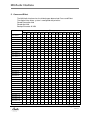
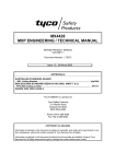
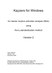
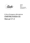
1
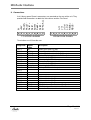
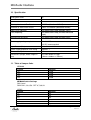
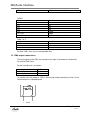
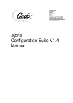
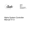
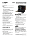
Audix Systems
Station Road,
Wenden,
Saffron Walden,
Essex,
CB11 4LG.
Telephone: +44(0)1799 540888
Facsimile: +44(0)1799 541618
www.tycosafetyproducts-europe.com
www.audixsystems.co.uk
MX/Audix Interface
User Manual: V1.4
MX/Audix Interface
1. Revision History
Version
1.0
1.1
1.2
1.3
1.4
Modifications
Original issue. (LJA review 17/11/03)
Modifications
Modifications
Mods Following comments from R&D
Mods Following comments from R&D
Date
13/10/03
25/11/03
21/01/04
10/02/04
11/02/04
© COPYRIGHT AUDIX SYSTEMS. 2005
DISCLAIMER
This manual contains information that is correct to the best of Audix Systems knowledge. It
is intended to be a guide and should be used as such. It should not be considered as a sole
source of technical instruction, replacing good technical judgement, since all possible
situations cannot be anticipated. If there are any doubts as to exact installation,
configuration and/or use,
call Audix Systems at+44 (0)1799 540888
ACKNOWLEDGEMENTS
All trademarks are recognised
Page 2 of 19
21030 V1.4
MX/Audix Interface
2. Models Covered
This user manual covers the following equipment
•
570.800.800 MX/Audix Interface – 32 Channel MX Voice Alarm Interface
3. Technical Support
In the unlikely event of you having problems with your MX/Audix Interface please contact
our Customer Services Department.
Audix Systems
Station Road
Wenden
Saffron Walden
CB11 4LG
Tel 01799 540888
Fax 01799 541618
Page 3 of 19
21030 V1.4
MX/Audix Interface
1.
REVISION HISTORY ...................................................................................................................... 2
2.
MODELS COVERED ...................................................................................................................... 3
3.
TECHNICAL SUPPORT ................................................................................................................. 3
4.
INTRODUCTION............................................................................................................................. 5
PRODUCT AIM: ...................................................................................................................................... 5
SYSTEM OPERATION: ............................................................................................................................ 5
5.
CAUSE AND EFFECT .................................................................................................................... 7
6.
MX INTERFACE OPERATIONAL DETAILS .................................................................................. 8
DEFINITIONS ......................................................................................................................................... 8
IMPORTANT SAFETY CONSIDERATIONS ................................................................................................... 8
CONNECTIONS TO ALARM CONTROL SYSTEM:......................................................................................... 8
TERMINATION OF SITE CABLES. .............................................................................................................. 8
7.
COMMISSIONING INFORMATION................................................................................................ 9
BACKGROUND TO THE MX/AUDIX INTERFACE:......................................................................................... 9
FUNCTION AND USE OF MODULES: .......................................................................................................... 9
7.1.1 Single Input/Output Module (SIO800) ................................................................................. 9
7.1.2 Relay Interface Module (RIM 800)..................................................................................... 10
INSTALLATION/COMMISSIONING PROCEDURE: ....................................................................................... 10
8.
PROCEDURE FOR REPLACING MX PANEL FIRMWARE AND PANEL CONFIGURATION ... 13
9.
CONNECTIONS............................................................................................................................ 16
10.
SPECIFICATION....................................................................................................................... 17
11.
TABLE OF JUMPER LINKS..................................................................................................... 17
12.
FMS OUTPUT CONNECTIONS ............................................................................................... 18
APPENDIX
12. MX FLOW CHART
13. SYSTEM SCHEMATIC
14. WIRING DIAGRAM
Page 4 of 19
21030 V1.4
MX/Audix Interface
4. Introduction
Product Aim:
The MX/Audix Interface allows transparent interface between MX and the Audix
Alpha System Controller, with a reduced quantity of interconnection cables to
minimise install costs.
The system allows a maximum of 16 Zones of Evacuation and Alert using the RBus
interface.
Fault monitoring of the Voice Alarm system is via the addressable loop, and a fault
tolerant backup Evac for all zones is also possible via the addressable loop.
Changes to the fire alarm cause and effect are simple, made using the MX
configuration software, the changes are mirrored through to the Audix Voice Alarm.
System Operation:
Under alarm conditions:
An RBus message is sent from the MX Fire panel to the remote MPM800. This will
switch the output of one of two XIOM boards mounted in the interface.
The XIOM outputs 1-8 are connected the Audix switch board D439RASSY
And outputs 9-16 are connected to D448RASSY
The switch boards translate the contact to serial data, which is transmitted to the
Alpha. The configurations in the Alpha are pre programmed (see below) and play
either the Evacuation or Alert message to a zone.
The configuration is such that if an Alert message is already playing in a zone, an
Evacuate message in the same zone will override it. The message keeps playing
until the RBus sends another message to stop it.
If a fault occurs with the RBus this is indicated in the MX panel and a fault warning
will be displayed. If the unit loses power then this is indicated by the SIO800
module, which again warns the MX panel that there is a fault.
If there is a failure of the monitored data line between the interface and the Alpha,
the Alpha shows a comms failure and indicates a system fault. This is in turn
relayed back to the MX panel via common fault output.
Page 5 of 19
21030 V1.4
MX/Audix Interface
The Incoming RBus data link is monitored; on failure of the RBus an indication is
displayed on the front panel of the MX.
When any alarm (Evac or Alert) is activated via the RBus the MX panel also
switches a RIM800 module (programmed at address 249). The output of this relay
is monitored by a general purpose input on the MPM800 board. If the MX panel
does not see this input change state within 20 seconds via the RBus then an
automated Evacuate of all zones is initiated. Therefore in the event of failure of the
RBus, total building Evacuation is possible under a fire condition.
In the event of total failure of the MX interface and/or the Alpha the fireman’s
microphone can be used in bypass mode to address all areas.
BS 5839 describes a requirement for ‘the voice-alarm system to latch on receipt of
a signal from the fire detection and alarm system until de-latched by a separate
command from the fire detection and alarm system’. The MX/Audix Interface is a
serial data linked interface for Audix PA VA systems that satisfies this requirement,
with monitoring directly on to the fire detection and alarm system.
The output connections of the interface are linked to the serial 485-interface card.
This connects the Alpha, which contains the emergency message cards.
The data link between the MX/Audix Interface and Alpha is continuously monitored
and its failure is reported to the master FMS. This will be indicated as a “COM”
Failure on the front panel of the Alpha and a “MISC” fault on the front panel of the
FMS
Whenever the fire alarm contact activates the MX/Audix Interface will send data to
the Alpha and trigger the emergency fire message.
Messages are stored as raw data files and not as simple tone generators, so any
voice and/or alarm message can be recorded and stored on the message cards.
Priorities and routing of messages are pre-configured within the Alpha matrix
Page 6 of 19
21030 V1.4
MX/Audix Interface
5. Cause and Effect
The MX/Audix Interface has the following pre determined Cause and Effect.
The Alpha Voice Alarm system is configured with priorities:
Zoned Evacuation 240
Zoned Alert 230
Backup Evacuate All 250
1
2
3
4
5
6
7
Zone
8
9
10
11
12
13
14
15
16
Evac Zone 1
Evac Zone 2
Evac Zone 3
Evac Zone 4
Evac Zone 5
Evac Zone 6
Evac Zone 7
Evac Zone 8
Evac Zone 9
Evac Zone 10
Evac Zone 11
Evac Zone 12
Evac Zone 13
Evac Zone 14
Evac Zone 15
Evac Zone 16
Alert Zone 1
Alert Zone 2
Alert Zone 3
Alert Zone 4
Alert Zone 5
Alert Zone 6
Alert Zone 7
Alert Zone 8
Alert Zone 9
Alert Zone 10
Alert Zone 11
Alert Zone 12
Alert Zone 13
Alert Zone 14
Alert Zone 15
Alert Zone 16
Backup Evac
Page 7 of 19
21030 V1.4
MX/Audix Interface
6. MX Interface operational details
Definitions
The Unit
Output
MX/Audix Interface
A serial to parallel converter, which is transmitted by the serial link
card D439 to the Alpha Voice Alarm system controller.
Alarm Input A monitored RBUS (RS 485) Serial Data connection from the fire
detection and alarm system, used to activate the Audix Voice Alarm
system
Fault Output This is monitored via the RS485 data by the Alpha comms
connection.
Fault Indication Contact Input module is wire on to the fire loop and indicated
availability of the Voice Alarm System
Important Safety Considerations
The MX/Audix Interface should be supplied from a fuse-protected 24V DC supply,
the fuse rating should be 500mA L T.
The MX/Audix Interface and associated equipment must not be exposed to dripping
or splashing.
Connections to Alarm Control System:
The unit will require the following connections to isolated contacts at the fire
detection and alarm system.
1.
One pair for RBus
2.
Two pairs for addressable loop
Termination of site cables.
The MX/Audix Interface chassis is hard wired from the unit to the ITP100 a special
termination panel fitted to a rail in the rear of the equipment rack. This panel is an
2
Audix systems part and allows connection of site cables up to 2.5mm .
There are extra terminals and connector on the unit to accommodate the system
fault outputs from an Audix Systems FMS system.
The terminal block arrangement is shown in a later section of this manual, for easy
installation it is silk-screened on to the PCB just below the terminal blocks.
Page 8 of 19
21030 V1.4
MX/Audix Interface
7. Commissioning Information
This document provides a commissioning engineer with a step by step
programming guide to the installation of the MX/Audix interface. Via the MX Panel
The 2U MX/Audix Interface housing consists of the following equipment:
2 x XIOM800 module – part no: 557.180.016
1 x MPM800 module – part no: 557.202.012
1 x SIO800 module – part no: 555.800.063
1 x RIM800 module – part no: 568.800.003
1 x D439R PCB ASSY – part no: 570.006.008
1 x D448R PCB ASSY – part no: 570.006.009
Background: The purpose of the SIO800 module is twofold, firstly the input side of
the module is connected to the global fault output of the Audix PA/VA system. Any
fault occurring on the Audix equipment will result in a general fault being displayed
on the MX panel. Secondly the output side of the module is connected to the Audix
equipment to provide a global Evacuation of the building should both the following
occur simultaneously:
a) There is a fault on the RBus and/or the MPM800
b) The MX panel is in a fire condition (Alert or Evacuation)
If condition (a) and (b) described above is in place then this will result in the Audix
rack being configured to provide a global Evacuation message to all zones
The function of the XIOM modules is to provide 16 zonal Alert and 16 zonal
Evacuate inputs into the Audix equipment.
Background to the MX/Audix Interface:
The purpose of this unit is to seamlessly integrate an MX addressable fire detection system
and an Audix voice Evacuation system. The unit will be entirely pre-wired and addressed,
making the installation and set up relatively straightforward and easy to carry out. The
installation engineer has to carry out the following tasks:
1. Connect the addressable loop to the rear of the unit, marked L+, L- and R+, R-.
2. Connect the RS485 Remote Bus, to the rear of the unit, marked RBus +VE and RBus –
VE.
Function and use of modules:
7.1.1 Single Input/Output Module (SIO800)
The input side of the module is connected to the global fault output of the Audix PA/VA
system. This module provides full fault monitoring of the Audix VA rack. Any fault occurring
Page 9 of 19
21030 V1.4
MX/Audix Interface
on the Audix equipment will result in a general fault (Audix general-purpose fault) being
displayed on the MX panel.
Secondly the output side of the SIO800 module is connected to the Audix global Evacuation
input. This will send a global Evacuation message to all floors of the building and it is
intended that all persons will leave the building upon activation of this message.
The output side of the module will only operate should the following conditions be
simultaneously present:
The MX fire panel has detected an alert or evacuation alarm on one of its configured
zones.
There is a fault on the RBus and/or the MPM800.
7.1.2 Relay Interface Module (RIM 800)
This relay module is activated whenever a fire occurs on the MX panel (alert or evacuation).
During the 20-second checking/testing period the RS485 Remote Bus and the MPM800 are
checked for integrity. If these are found healthy, then the RIM800 is switched off, and no
further fall-back action is taken.
Installation/Commissioning Procedure:
1. The MX addressable loop connections can be found at the rear of the 2U-interface
housing. Connect the MX addressable loop, (L+, L- and R+, R-) as per the connections
shown on the label. Check you have the polarity correct and check loop in and out for
correct voltage (approx. 37.5V DC).
2. Connect the 2 wire remote bus (RS485, +VE and -VE), the connections can be found at
the rear of the 2U interface housing, connections are shown on the label, check for
correct polarity.
3. Note: the Single Input/Output Module (SIO800) within the housing has been preprogrammed its address is 250 (do not change the address).
4. Note: the Relay Interface Module (RIM800) within the housing has been preprogrammed its address is 249 (do not change the address).
5. Note: the Multi-Purpose Interface Module has been pre-configured via the binary dipswitches on the PCB, its address is number 15 (RB15)
6. In MX Consys open up UK Template (only version 5 or higher contain the Audix support
in the UK Template).
7. Add a Group Control Action, Activate / NoAction, from Group 133 Fire Alarm Status to
Group 465 Single Shot Fire Alarm (Audix). This is an essential connection that MUST be
configured in order to get the emergency operation in the case of fault.
8. Within Points, select the correct loop (A-D) then program the single input/output module
(SIO800) as address 250. Assign it to Group 464 Audix (SIO) Interface and to an
appropriate zone.
Page 10 of 19
21030 V1.4
MX/Audix Interface
9. Within Points, select the correct loop (A-D) then program the relay interface module
(RIM 800) as address 249. Assign it to Group 462 Audix Path Check (RIM) OP and to an
appropriate zone.
Page 11 of 19
21030 V1.4
MX/Audix Interface
10. Within Regions select RB15 and set its unit name as a XBB and then set its Xbus
template as ‘Audix 16’, this will automatically set up the two XIOM’s connected to the
MPM800. This will assign all the alert outputs to group 459 and the evacuation outputs
to group 460. Check they have been correctly assigned by checking within Point Region
RBus 15/Xbus and then press F10 to confirm. Check that addresses 1-16 are assigned
to the Audix Evac group 460, and that addresses 17-32 are assigned to the Audix alert
group 459.
11. Within Point Region RBus 15, select Real Points, then select Real Point number 4,
ensure that this general purpose input is assigned to group number 466 (Audix Alarm
Ackn I/P)
12. The Audix/MX interface programming is now complete
13. Program the rest of the loop and ancillary functions as required
14. Download the appropriate MX firmware file.
15. Download the MX configuration file.
Page 12 of 19
21030 V1.4
MX/Audix Interface
8. Procedure for replacing MX panel firmware and panel configuration
This procedure gives step by step instructions on how to replace both MX firmware and MX
Configuration. It is useful when upgrading MX panel firmware or ensuring that both the
panel firmware and configuration files are “clean” upon initial commissioning.
1. Make link H3 (top) on the CPU card.
2. Press and hold the red reset button on the CPU card until green watchdog led on the
CPU card turns off momentarily. This will result in the panel beeping rapidly, in addition
the “processor fault” led on the front cover will illuminate. (see note 1 below)
3. Press the red reset button S8 on the OCM (inside front cover). This will stop the rapid
beeping and the processor fault led will go off. The panel will now beep at less regular
intervals and after approximately 15 seconds the LCD display will go blank except for the
message “ RS 485 Comms Error”.
4. With your download lead plugged into COM2 on the FIM , start a Firmware download
from your
Laptop by choosing “Transfer” and then “Firmware”. You will be presented with a choice
box displaying the file “MX version *.*.dwn” (see note 2 below).
5. Highlight the file “MX version *.*.dwn” by clicking on it and the press the “open” button
on the bottom right hand side. This will start the firmware download. The download will
take approximately 5 minutes. During this time the panel will continue to beep slowly
and will continue to display the message “RS 485 Comms error” on the LCD display.
6. While the firmware download is taking place make link H2 (bottom) on the CPU card.
7. On completion of the firmware download the laptop will display a message “ Remove
Header link H3 to restart panel”.
8. As requested remove link H3 (top) on the CPU card and confirm you have done this by
clicking OK.
9. The panel will once again start to beep rapidly and the “processor fault” led on the front
cover will illuminate.
10. Press the red reset button S8 on the OCM (inside front cover). This will stop the rapid
beeping and the “processor fault” led will go off. The panel will now beep at less regular
intervals and will continue to display the message “ RS 485 Comms Error” on the LCD
display.
11. With your download lead still plugged into COM2 on the FIM, start a configuration
download from your laptop by choosing “Transfer” and then “Download Configuration”.
By default this will be a full download, you will not get the option to simply download
Page 13 of 19
21030 V1.4
MX/Audix Interface
modifications. You may also be asked if you wish to synch the panel time to the time on
the laptop. If this happens say yes by clicking OK.
Page 14 of 19
21030 V1.4
MX/Audix Interface
12. While the configuration download is in progress remove link H2 (bottom) on the CPU
card.
13. On completion of the configuration download the laptop will ask if you wish to perform a
panel restart. Say yes by clicking OK.. The laptop will inform you that the “panel restart
request has been sent” click OK again. After a few seconds you will see the LCD
display re-write and the panel start to initialise with your new firmware and configuration.
Note 1. Pressing the reset button on the CPU card momentarily down powers the
processor. The processor will then read the link settings you have made when it is
switches back on. Turning the panel off completely and then turning it back on has exactly
the same effect. It may, in some instances, be preferable to use this method because you
will re-initialise not only the CPU card but also the FIM.
Note 2. If the file presented in the choice box is incorrect. The correct dwn file can be
found by selecting the following path on the choice box; C:\Program files\Tyco EPG\MX
Consys v*.* .
Note 3 Prior to upgrading from ver1.* firmware to ver2.* firmware and later, ensure that the
boot rom chip on the CPU card is version 1.2. (Version 1.1 boot ROM will work for the UK
template but with some minor limitations. Please check prior to use)
Page 15 of 19
21030 V1.4
MX/Audix Interface
9. Connections
TO VOICE ALARM
L+In
L- In
L+Out
L- Out
RBUS +
RBUS -
0V
+24V
FAULT+
FAULTData1 +
Data1 Screen
Data2 +
Data2 EVAC ALL
2 off 10 way green Phoenix connectors are mounted on the rear of the unit. They
provide field connections to both the Voice Alarm and the Fire Panel.
FROM FIRE PANEL
Terminations are 2.5mm dia max
Plug/Term.
PL1/1
PL1/2
PL1/3
PL1/4
PL1/5
PL1/6
PL1/7
PL1/8
PL1/9
PL1/10
PL2/1
PL2/2
PL2/3
PL2/4
PL2/5
PL2/6
PL2/7
PL2/8
PL2/9
PL2/10
Signal
name
0V
+24V
FAULT
FAULT
Data 1 +
Data 1 Screen
Data 2 +
Data 2 EVAC ALL
Description
L+
LL+
LRBUS+
RBUS-
Addressable Loop 1 (+)
Addressable Loop 1 (-)
Addressable Loop 2 (+)
Addressable Loop 2 (-)
RBUS Monitored Serial Link to Fire Panel
RBUS Monitored Serial Link to Fire Panel
Connection For data cable screen
Power from Audix ITP100
Power From Audix ITP100
System Fault wired for Audix FMS output
System Fault wired for Audix FMS output
Data 1 to Audix ITP100
Data 1 to Audix ITP100
Connection For data cable Screen
Data 2 to Audix ITP100
Data 2 to Audix ITP100
Back up EVAC control output
Page 16 of 19
21030 V1.4
MX/Audix Interface
10. Specification
Evacuation Zones
16
Alert Zones
16
Primary Interface to Fire Panel
MX RBus (Monitored RS485)
Interface to Voice Alarm matrix
PMCV 16 Protocol. (Monitored RS485)
RBus Fault Indication
Via Addressable Loop (RIM800, Relay)
Fault Reporting
Via Addressable Loop (SIO800, Monitored
Input)
Backup Evac All Zones
Via Addressable Loop (SIO800, Relay)
Power supply voltage required:
20 – 28V DC
24V DC recommended
Input Current (Max)
280mA from a 24V
Power supply protection fuse rating.
500mA L T
Power consumption:
7W max.
Dimensions (length, width, Height in
mm)
19” Rack Width 2U High
(89mm x 480mm x 370mm)
11. Table of Jumper links.
MBM800
Jumper
JP1
JP2
JP3
JP4
Position
Fitted
Fitted
Fitted
Fitted
MPM800 Switch Settings
SW1 Local
SW2 ON 1,2,3,4,5,6. OFF 6,7,8,9,10
XIOM1
Jumper
H1
H2
H3
H4
LK1
U1 + U4
Position
3-4
3-4
3-4
3-4
Omit
Open
Page 17 of 19
21030 V1.4
MX/Audix Interface
U2 + U3
33 Ohm resistor pack fitted
XIOM2
Jumper
H1
H2
H3
H4
LK1
U1 + U4
U2 + U3
Position
3-4
3-4
3-4
3-4
Fitted
Open
33 Ohm resistor pack fitted
D439 1 & 2
Jumper
LK1
LK2
LK3
Position
Omit
2-3
1-2
All other PCB’s have no user configurable links
12. FMS output connections
The fault outputs of the FMS are located on the 9 pin D connector on the back of
the master FMS Panel.
System fault pin out is as follows:
Normally Closed
Common
Normally Open
Pin 7
Pin 3
Pin 8
To monitor the Fault output of FMS is achieved by fitting monitoring resistors to the
switch contact as indicated below.
+
Fault
-
Page 18 of 19
21030 V1.4
MX/Audix Interface
Page 19 of 19
21030 V1.4