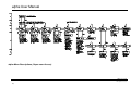
1
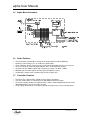
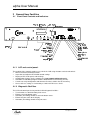
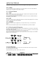
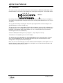
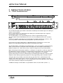
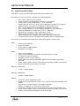
Audix Systems,
Station Road,
Wenden,
Saffron Walden,
Essex,
CB11 4LG.
Telephone: +44(0)1799 540888
Facsimile: +44(0)1799 541618
www.tycosafetyproducts-europe.com
www.audixsystems.co.uk
Alpha System Controller
Manual V1.5
alpha User Manual
Revision History
Versio
n
1.0
1.1
1.2
1.3
1.4
1.5
Modifications
Date
Initial Draft
Updated From Comments
Revised to include modifications for V1.02 software
Revised document layout
Revised & additional LVD safety instructions CN3311
Add Virtual SIU functional description
14/7/99
4/8/99
22/9/99
25/2/00
30/11/00
21/7/03
© Copyright Audix Systems. 2005
DISCLAIMER
This manual contains information that is correct to the best of Audix Systems knowledge. It is
intended to be a guide and should be used as such. It should not be considered as a sole
source of technical instruction, replacing good technical judgement, since all possible situations
cannot be anticipated. If there are any doubts as to exact installation, configuration and/or use,
call Audix Systems at +44 (0)1799 540888
ACKNOWLEDGEMENTS
Windows™, Windows 95™ and Windows 98™ are trademarks of Microsoft Corporation
All other trademarks are recognised
Page 2 of 39
21013 alpha user v1.5.doc
alpha User Manual
Models Covered
This user manual covers the following equipment
•
•
Alpha System Controller
ITP100 Input Termination Panel
Alpha System Controller:
•
•
•
•
AL1000 – standard Alpha System Controller.
AL1100 – with 1 message card
AL1200 – with 2 message card
AL1300 – with 3 message card
Technical Support
In the unlikely event of you having problems with your alpha system controller
please contact our Customer Services Department.
Audix Systems
Station Road
Wenden
Saffron Walden
CB11 4LG
Tel 01799 540888
Fax 01799 541618
Development
Our Research and Development Department are continuously improving the operation and
functionality of our products. If you have any comments on future requirements of our products
please contact our R & D department at the above address
Page 3 of 39
21013 alpha user v1.5.doc
alpha User Manual
Table of Contents
REVISION HISTORY .................................................................................................................... 2
MODELS COVERED .................................................................................................................... 3
TECHNICAL SUPPORT ............................................................................................................... 3
DEVELOPMENT ........................................................................................................................... 3
1
SPECIFICATION ................................................................................................................... 6
1.1
1.2
1.3
1.4
1.5
1.6
1.7
1.8
2
GENERAL USER FACILITIES ............................................................................................ 11
2.1
3
FRONT PANEL CONTROLS AND INDICATORS. ..................................................................... 11
ACCESSING CONTROLS AND PROGRAMMING THE ALPHA....................................... 13
3.1
3.2
3.3
3.4
3.5
4
SPECIFICATION.................................................................................................................. 6
FRONT VIEW ..................................................................................................................... 7
BACK VIEW ....................................................................................................................... 7
BRIEF DESCRIPTION .......................................................................................................... 7
ALPHA BLOCK SCHEMATIC ................................................................................................. 8
AUDIO FEATURES .............................................................................................................. 8
CONTROLLER FEATURES ................................................................................................... 8
MESSAGE CARDS - D776 (OPTION) ............................................................................... 10
ACCESS LEVEL 1. “PASSER BY”.................................................................................... 13
ACCESS LEVEL 2 “OPERATOR”..................................................................................... 13
ACCESS LEVEL 3 “MAINTENANCE ENGINEER” ............................................................... 13
ACCESS LEVEL 4 “COMMISSIONING ENGINEER” ............................................................ 15
ACCESS LEVEL 5 “SUPER-USER - OEM” ........................................................................ 15
CONFIGURATION & OPERATIONAL FEATURES ........................................................... 18
4.1
ALPHA CONFIGURATION SUITE (ACS)............................................................................... 18
4.2
I/O AND ‘BUTTON’ FEATURES ........................................................................................... 19
4.3
I/O CONTROL INPUTS ...................................................................................................... 20
4.4
I/O CONTROL OUTPUTS................................................................................................... 21
4.5
I/O PORT CONTROLLER PIO OPERATION ......................................................................... 21
LIVE INPUT MONITORING ............................................................................................................ 21
5
ADDITIONAL SYSTEM HARDWARE................................................................................. 22
5.1
5.2
6
ITP100 TERMINATION PANEL........................................................................................... 23
INPUT CONTROLLER PANELS ........................................................................................... 24
FAULT MONITORING FEATURES .................................................................................... 25
6.1
6.2
6.3
SUPPLY MONITORING ...................................................................................................... 25
AUDIO MONITORING ......................................................................................................... 25
DATA COMM’S MONITORING ............................................................................................ 27
7
TROUBLE SHOOTING........................................................................................................ 28
8
WARRANTY ........................................................................................................................ 29
8.1
8.2
8.3
8.4
8.5
8.6
8.7
8.8
PERFORMANCE ............................................................................................................... 29
DELAYS IN DELIVERY ....................................................................................................... 29
STORAGE........................................................................................................................ 29
DAMAGE OR LOSS IN TRANSIT (UK) ................................................................................. 29
DAMAGE OR LOSS IN TRANSIT (EXPORT) .......................................................................... 29
LIABILITY FOR DEFECTS ................................................................................................... 29
INSTALLATION AND COMMISSIONING ................................................................................. 29
ENVIRONMENT ................................................................................................................ 30
Page 4 of 39
21013 alpha user v1.5.doc
alpha User Manual
8.9
8.10
9
TITLE OF GOODS ............................................................................................................. 30
LAWS.............................................................................................................................. 30
SAFETY CONSIDERATIONS ............................................................................................. 31
9.1
9.2
SAFETY CONSIDERATIONS FOR SYSTEM DESIGN AND INSTALLATION.................................. 31
SAFETY CONSIDERATIONS FOR SYSTEM MAINTENANCE .................................................... 31
10
MAINTENANCE ............................................................................................................... 32
11
GLOSSARY ..................................................................................................................... 33
12
REAR PANEL PIN-OUTS ................................................................................................ 35
13
ELECTRICAL SCHEMATICS .......................................................................................... 38
Page 5 of 39
21013 alpha user v1.5.doc
alpha User Manual
1 Specification
1.1
Specification
Model
Matrix Capacity
Audio input
Message Card (optional)
Audio output
Audio output monitoring point (front panel)
Frequency Response (± ½dBu )
EQ controls
Bass
Treble
Distortion
Signal/Noise (0dBu input)
Sensitivity (0dBu output)
Control panel data port
I/O control input port (switch-in)
I/O control output port (switch-out)
I/O control output port sink current
I/O control output port open circuit voltage
Alpha & Alpha network System Controller
15 x 16 Analogue Audio Switching Matrix
12 x Electronically balanced line level, 0dBu 10K
ohm
3 x Cards with max of 10 messages/card, 0dBu 40
ohm
16 x Electronically balanced line level
3.5mm jack socket (output select via LCD control
panel)
20Hz to 20kHz
± 10 dBu at 100Hz
± 10 dBu at 10kHz
Better than 0.05% THD
Better than –80dBu (22Hz-22kHz)
-30dBu to +25dBu
8 x serial RS485 data links (unique protocol)
16 x input port 0V to 5V (configurable active high or
low)
16 x output port open collector (configurable active
state)
(wakeup feature utilises output port 16)
200mA max
50V max
General:
Mains supply (V)
Backup supply input
Supply output (external equipment)
Power Consumption (W) (with 3 message
cards)
Heat Dissipation (W) (with 3 message cards)
Dimensions(length, width, Height in :mm)
Weight (kg)
Operating temperature range (°C)
Standards
230V AC. +/- 10%, 50-60Hz
24V DC (nominal). To be fused at source 10A max.
24V DC (nominal) 2 Amp max
19W (excluding auxiliary power output)
19W
19” Rack Width 2 U High
(89mm x 432mm x 325mm)
7 kg
0°C to 40°C
Meets or exceeds the requirements of BS5839.
Compliant with EMC standards, EN 50081-1:1992,
EN 50082-1:1998, EN 60555-2:1987
Compliant with LVD safety standards; BS
EN60065:1998
Back up Supply Consumption (with mains disconnected)
This is current drawn from the 24V battery supply under quiescent conditions.
Current drawn from the auxiliary supply output must also be taken into consideration.
AL1000 - 218mA
AL1100 - 250mA
AL1200 - 282mA
AL1300 - 314mA
Approximate current requirements from standard desk microphone units.
SMU8 – standard
75mA quiescent
145mA maximum (LED’s illuminated)
SMU16 – standard
80mA quiescent
220mA maximum (LED’s illuminated)
Page 6 of 39
21013 alpha user v1.5.doc
alpha User Manual
1.2
Front View
System Controller
1.3
Back View
FMS
(master)
FMS
(terminator)
2A
1.4
B
D777
A
D785
A
Brief Description
The purpose of Alpha System Controller is to switch or ‘route’ Public Address / Voice Alarm
signals from an announcement station i.e. a microphone to a speaker zone or zones.
The Alpha can interface various announcement stations and other line level audio inputs such
as a CD or cassette player.
The audio switching matrix with digitally controlled input volume, bass and treble controls,
switches or ‘routes’ the audio signals to the power amplifiers.
Requests for a ‘route’ from the announcement stations are made to the microprocessor within
the Alpha.
The microprocessor manages these requests with regard to their priority.
On a request being valid i.e. no request of a higher priority is being made for the same outputs
or ‘destinations’ the audio switching matrix is ‘routed’.
The announcement station may have one or multiple zone (routing) selectors.
The configuration of these selectors can be programmed with regard to the input source, output
destination or destinations and their priority.
This configuration is held in memory within the Alpha.
Page 7 of 39
21013 alpha user v1.5.doc
alpha User Manual
1.5
Alpha Block Schematic
1.6
Audio Features
•
•
•
•
•
•
•
1.7
•
•
•
•
The D774 audio card provides circuitry for all audio switching and conditioning.
Routing is achieved by a 15 x 16 audio cross-point matrix.
Up to 3 optional “plug in” D776 message cards maybe fitted with out loss of user inputs.
12 Line level inputs each with digital Volume, Bass, and Treble EQ controls.
16 Balanced Line (0dBu) outputs with a frequency response of 20Hz - 20kHz.
Monitoring of the matrix outputs via front panel headphone socket.
Control of the matrix card is performed by the D777 alpha CPU.
Controller Features
The D777 CPU card provides control of all the alpha’s operations.
The CPU card features a 32-bit processor with RAM and Flash memory.
The Flash memory contains the alpha firmware and the alpha configuration which can be
downloaded from a PC via the engineers port
‘D’ type plugs located on the rear panel provide connection for I/O and serial data ports.
Page 8 of 39
21013 alpha user v1.5.doc
alpha User Manual
1.7.1 Parallel I/O Ports
•
•
•
•
•
•
•
The alpha has 16 open collector switched outputs. These can typically be used to provide
rd
volume control override (VOR), channel live, busy or to control 3 party equipment.
Output 16 is typically reserved for the WAKE UP signal to the vector amplifiers.
Systems using SMU16 Mk1 and PMCV microphone units one output must be used to
provide a chime/enable signal.
The alpha has 16 x 5volt logic level switch inputs
These inputs maybe used as PTT’s inputs from SMU1, fist mic, non-monitored alarm
contacts, timer contacts etc.
The configuration of both input and output ports is programmable via the ACS alpha
Configuration Suite.
Each I/O port maybe configured as either active high or active low.
1.7.2 Serial Data Ports
•
•
•
The alpha has eight RS485 Serial data ports. These data ports are designed to interface to
Audix SMU’s (8 and 16), VMU’s and MSL multiple selector microphone/control units.
The microphone/control unit zone selectors activate routing configurations held within the
alpha.
Each serial link port maybe configured to report microphone/control unit and data link faults
to the FMS system.
1.7.3 Engineers Port.
•
•
•
•
RS232 engineers ‘ENG’ ports are provided at both the Front and Rear panels.
An alpha configuration PC maybe connected to this port via a standard 9 way Null modem
cable.
Using the PC based Audix Configuration Suite, current configuration settings can be
uploaded and interrogated or new system configurations written and downloaded.
Firmware upgrades are also possible on-site via the engineers port.
Page 9 of 39
21013 alpha user v1.5.doc
alpha User Manual
1.8
•
•
•
•
•
•
Message Cards - D776 (OPTION)
Each Message Card fitted to the alpha features:
Digital Volume, Bass & Treble controls on each message card.
20kHz surveillance tone generator on message cards.
Either SIU’s or alpha I/O ports (switch-in) may control the message playback and routing.
Each message card provides single audio channel playback. If two simultaneous audio
signals are required, for example “evacuate” and “alert”, then two message cards are
required.
Up to two EPROM’s maybe fitted each with 4 or 8 Megabits of memory
This memory space maybe configured with up to 10 messages or ‘segments’, the sum of
the time required by all the segments determines the amount of memory required.
Record Times at supported sample rates
8kHz
12kHz
16kHz
(reproduced bandwidth)
(~3.5kHz bw)
(~5.5kHz
bw)
(~7kHz bw)
130 sec
86 sec
65 sec
65 sec
43 sec
32 sec
16bit recording on 2 x 8 Mbit EPROM
16bit recording on 2 x 4 Mbit EPROM
•
•
•
•
•
•
Each message segment can be configured as a ‘Message’ with independent Volume, bass,
treble and playback modes (play while held, play to end.)
It is possible to configure each message with a silent ‘gap’ of 0 to 255 seconds after playing,
before the message is repeated
Messages can be selected by a source button, and then separately routed by a zone
selector on a SIU i.e. from a control panel one of a number of messages maybe selected
using the source selector. This can then be routed by the zoning keys.
Where this type of operation is configured the user can elect to use the ‘normal’ input
source such as the microphone by selecting the zone and PTT (press to talk) button, but not
selecting a message source.
Message cards can be configured as surveyed sources, this is essential for critical path
monitoring. The message card would be configured to produce an inaudible continuous
20kHz tone. The matrix is activated every 30 seconds to switch this and other surveyed
sources (message card or input) in turn to the surveyed outputs, resulting in an output pulse
every 30 seconds, this is detected by the FMS monitoring equipment. If more than three
inputs are programmed for surveillance, the FMS monitoring response time will exceed the
100second limit specified by BS5839.
Audix Systems offers a service to prepare, record and programme the messages on to
EPROM
Engineers note: It important to note that adjusting the volume of the emergency messages, after
a system has been accepted by a Fire Officer should be under taken with great care.
Adjustment of these controls will effect the sound pressure level at all the speaker zones.
Page 10 of 39
21013 alpha user v1.5.doc
alpha User Manual
2 General User Facilities
2.1
Front Panel Controls and indicators.
System Controller
2.1.1 LCD and control panel:
The majority of the controls maybe accessed via the LCD using 4 buttons and a thumb wheel:
• Menus of control and utility functions.
• Inspection and adjustment of Audio control settings.
• Display of CPU fault reports and warnings.
• Configuration changes via the control panel (non-network alpha units only).
• Activation of embedded program firmware download to Flash memory (via PC).
• A means to verify configuration and firmware file names held in the flash memory.
• Access to these settings is restricted by a number of PIN access levels.
2.1.2 Diagnostic Facilities.
The LCD and control panel also provides built in diagnostic facilities:
• Test functions are built into front panel menus.
• Echo of serial unit button status.
• Activation (overriding) control of serial unit button status.
• Echo of I/O port status to the display
• Activation (overriding) control of I/O port states.
Page 11 of 39
21013 alpha user v1.5.doc
alpha User Manual
2.1.3 Memory Protection Facility.
A front panel mounted key switch provides a memory write-protect lock to prevent accidental
reprogramming or erasing of the alpha settings. The key switch also allows access to the set-up
menus without the need to enter the PIN code).
2.1.4 Reset Facility.
A non-latching master reset switch accessible only with a small implement resets all of the cards
within the alpha.
2.1.5 LED Indications
The front panel of the alpha is equipped with LED indications for fault warnings and PSU status
(FMS).
Front panel LED Indicators as shown from right to left are described below.
LED Name
ON
Colour
Green
Fail Mains
Fail Batt
Fail Chg
Fail Misc
Fail com
Yellow
Yellow
Yellow
Yellow
Yellow
Memory Conf
Yellow
Memory Prog
Watchdog
Warn
Yellow
Yellow
Description
This indicates the alpha is running either from Mains or
Battery.
Indicates the mains supply to the alpha has failed.
Indicates battery supply failure.
Indicates battery charger failure or disconnect.
Indication of miscellaneous faults.
Indicates communications errors or failure between the alpha
and serial data control panels.
Utilising the LCD menu system the faulty serial link can be
located.
Indicates configuration memory error (resulting in a CRC
error).
Indicates embedded program (firmware) memory error.
A latched indication of processor reset or ‘watchdog’.
A button is provided to cancel this fault indication.
The alpha also provides an opto-isolated bus interface to the Audix Fault Monitoring System
(FMS).
Failures relating to the alpha are indicated at the FMS master panel along with faults from other
system equipment, relating to that suite of equipment racks. A ‘one-shot’ pulse to the FMS is
provided on each fault occurring within the alpha and displayed as a “New Fault”.
Page 12 of 39
21013 alpha user v1.5.doc
alpha User Manual
3 Accessing controls and programming the alpha.
Restriction of un-authorised tampering is a prime consideration in alpha based systems. A
progressive series of access restrictions has been designed into the alpha. These access level
restrictions directly correspond with the requirements of the UK Code of Practice BS5839 and
are listed in the table.
Access
Type
Passer By
Operator
Access Level
Engineer
Level 3
Engineer
Super User
Level 4
Level 5
Level 1
Level 2
Alpha
Protection
Locked cabinet
Password 1
(1383)
Password 2
(1039)
Key switch
Hardware
Config. Suite Protection
Software Issued to registered users only
Password 1 (1383)
Password 2 (1039)
Firmware requires (controlled software)
Passwords Set In config suite (OLDA11)
The actions allowed to users at each level are detailed in the following table, with important
points described in more detail in the following paragraphs of section 3.
Menu
Vol/EQ/surv
Virtual SMU
Headphone
monitor
View/edit
Configuration
Upload Config
Download
Config
Clear faults
I/O port control
Live inputs
Modify
Firmware
Modify
Hardware
Set Password
Level 1
access
No access
No access
No access
Level 2
access
View
View
Use
Level 3
access
View
Operate
Use
Level 4
Level 5
Change
Operate
Use
Change
Operate
Use
No access
View
View
Edit
Edit
No
No
Yes
No
Yes
No
Yes
Yes
Yes
Yes
No access
No access
No access
No
Clear FMS
faults
View
View
No
Clear SIU
counters
Operate
View
No
Clear SIU
counters
Operate
View
No
Clear SIU
counters
Operate
View
Yes
No
No
No
No
Yes
No
No
No
No
Yes
3.1
Access Level 1.
“Passer by”
3.2
Access Level 2
“Operator”
3.3
Access Level 3
“Maintenance Engineer”
Level 1 access is achieved by installing the alpha behind glass doors, making fault indications
visible, but restricting tampering.
Similarly a ‘Passer By’ should not be allowed access to the PC based configuration suite.
Password 1 allows the user to inspect configuration, volume, EQ and Surveillance setting from
the alpha front panel, and to Upload the alpha configuration to a PC and view it with the
configuration suite.
There is no effect on system operation, even if left accidentally open.
Using password 2 will allow most of the “Engineer” functions, with the exception of downloading
configuration changes to the alpha, or making changes from the front panel.
Page 13 of 39
21013 alpha user v1.5.doc
alpha User Manual
Configuration changes can be made in the configuration suite, but the file cannot be
downloaded.
This level allows the Maintenance Engineer to operate the diagnostic ‘Virtual SIU’ and I/O port
controller. Note that these operations may intrude on the normal operation of the system.
Page 14 of 39
21013 alpha user v1.5.doc
alpha User Manual
3.4
Access Level 4
“Commissioning Engineer”
On turning the key switch the password is bypassed and full level 4 access is granted to the
user.
This allows downloading of configuration changes to the alpha. Configuration changes to
Volume, EQ and surveillance settings can also be made from the front panel at this level.
Upgrading of Firmware in the alpha at ‘access level 4’ is generally not allowed in BS5839
compliant systems. However for other systems it may be appropriate and the ability to perform
firmware upgrade at ‘access level 4’ may be permitted by the “Level 5” user, and is described
below.
Note: For Level 4 User access a Key is required, but not a password.
3.5
Access Level 5
“Super-user - OEM”
By use of the key switch and an internal jumper J1 (accessible only with the use of special tools)
‘Level 4 user’s can be restricted from performing a firmware download.
A firmware upgrade is achieved by downloading new embedded software via the ENG port into
the flash memory.
To prevent any firmware changes it is possible to fit Flash ROM devices with “Sector Protection”
set.
This is carried out the use of an external programming device.
This action cannot be reversed by any actions to the alpha at access levels 4 or below. This is
not considered a standard feature and should only be implemented when absolutely necessary.
Note that “Sector Protection” is only available when AMD Flash ROM chips are used in the
alpha.
Level 5 Access to the configuration suite allows the user to change the lower level passwords
and download them to the alpha. Password can only be modified from the alpha configuration
suite at Super-user level. Changes to the passwords cannot be made from the front panel.
In essence these level 5 privileges allow the Engineer access level 4 to make use of distinct
advantages of the alpha’s Flash Memory system in applications where restrictions of BS5839
are not appropriate.
“OEM” access requires the removal of the cover from the alpha, which in turn requires the unit
to be slid out of its normal location within the equipment rack.
Setting the Jumper J1 on the D777 CPU Card configures the level of memory write protection
the key switch.
*
OMIT
Key enables writing to configuration memory only
FIT
Key enables writing to program (Firmware) and configuration
memory
Default Position *
Level 5 User access, Key and special tools required (but No password).
Note:
For BS5839 compliant systems J1 on the D777 CPU Card MUST
be removed.
Page 15 of 39
21013 alpha user v1.5.doc
alpha User Manual
Page 16 of 39
21013 alpha user v1.5.doc
alpha User Manual
alpha Menu Descriptions (Super-user Access)
Page 17 of 39
~
21013 alpha user v1.5.doc
alpha User Manual
4 Configuration & operational Features
4.1
alpha Configuration Suite (ACS)
Before the alpha can be used in a ‘system’ it must be configured using the alpha configuration
suite.
The alpha system maybe engineered and configured to meet specific customer requirements.
Refer to the alpha Configuration Suite user manual.
The alpha is a fully configurable switching matrix, allowing the user to configure zone selectors
with sources, destinations, priorities, volume, EQ levels, and messaging facilities.
The ACS is a Windows based programme that allows the user to configure the various settings
available within the ACS. The ACS generates an ASCII text file from these settings.
The ASCII text file can be downloaded to the alpha or uploaded to the configuration PC for
interrogation and modification.
The ACS also checks for syntax errors within the configuration.
Programming from the PC is performed using a standard Null modem cable between a spare
comms port on the PC and the alpha’s ENG port.
Uploading and downloading files is possible while the alpha is operating with no significant loss
of functionality, other than any programming changes.
The alpha MUST be restarted for downloaded changes to take effect. This will occur
automatically on completion of the download.
On the front panel dedicated menus are provide to allow easy adjustment of settings such as
volume, bass and treble etc.
More advanced programming is also possible using the built in alpha text line editor. Any
changes made to the configuration from the front panel WILL NOT be checked for syntax errors.
This option is disabled on the Network alpha versions.
When the alpha is rebooted the configuration is read in to the CPU and compared against a
template, any line not compatible with the template will be ignored.
The alpha maybe sold without the ACS but the advantages of this software programmer far
outweigh the difficulty of programming the simplest systems from the alpha front panel.
The ACS software is protected from illegal copying by use of a hardware “dongle”
Page 18 of 39
21013 alpha user v1.5.doc
alpha User Manual
4.2
I/O and ‘Button’ Features
Inputs
AUDIO in
(Source)
Line Level
Outputs
AUDIO out
(Destination)
CONTROL (LIVE)
(I/O port switch-out)
Message
CONTROL (BUSY)
(I/O port switch-out)
CONTROL
(Serial Link)
Serial control unit
i.e. SMU8
microphone
CONTROL(TRIGGER)
(I/O port switch-out)
CONTROL(PTT)
(I/O port switchin)
N/O Switching
Contact
N/C Switching
Contact
Line Level O/P to
Amplifier(s) etc.
Output pin enabled when
audio input channel active
‘LIVE’
Output pin enabled when
audio output or
destination active ‘BUSY’
Output pin enabled when
Button (serial unit) or
switch-in pin active
‘TRIGGER’
(operates separately to
matrix routing)
4.2.1 Priorities
Both PTT type I/O ports and buttons of a serial input unit are configured with priority settings.
Busy thresholds within the alpha can be configured at any priority level.
There are two busy thresholds, one of which is the level at which the busy indicators are
activated on the SIU serial interface units. The other is the level at which the busy I/O output
ports are activated.
Where buttons are configured below the busy threshold busy outputs are not generated. This
type of configuration would typically used for background music applications.
4.2.2 Button Over-ride
This is a configurable feature of the alpha routing selectors i.e. either a serial control unit button
or the switch-in ‘PTT’ ports.
Where button X is pressed the signal is routed to Zones 1-4
Button Y will appear busy, this is because it shares Zone 4
If Button Y user has a lower priority ‘his’ call can NOT be made.
Page 19 of 39
21013 alpha user v1.5.doc
alpha User Manual
Where button Y is pressed and a the signal is routed to Zones 4-7
Button X will appear busy, this is because it shares Zone 4
If Button X user actives ‘his’ button then Button Y will be overridden i.e. Button Y audio will be
disconnected from zones 4-7 and Button X audio will be connected to Zones 1-4.
4.2.3 Zone Over-ride
This is a configurable feature of the alpha routing selectors i.e. either a serial control unit button
or the switch-in ‘PTT’ ports.
Zone override is where only conflicting zones of a low priority user are overridden. Unlike button
override where a single conflicting zone on button overrides the whole of the lower priority
button.
Where button X is pressed the signal is routed to Zones 1-4
Button Y will appear busy, this is because it shares Zone 4
If Button Y user has a lower priority, the call will only appear at Zone 5,6 & 7 (Button X has zone
4).
Where button Y is pressed the signal is routed to Zones 4-7
Button X will appear busy, as it shares Zone 4
If Button X user actives ‘his’ button then Button Y will be overridden on zone 4 only i.e. Button Y
audio will be disconnected from zone 4 and Button X audio will be connected to Zones 1-4.
4.2.4 Zone Selector Button Indications
Serial control units such an the SMU8 microphone have busy (red) and Confirm (green)
indicator above each zone selector button.
When broadcasting to selected destinations the LED indications are as follows:
Busy only
- All destinations are being utilized by a higher priority user.
Confirm only
- All selected destinations have been achieved.
Busy & Confirm -Only some of the selected destinations have been achieved.
i.e. If button Y is pressed and routed to Zones 4-7
Button Y will show Confirm
Button X will appear Busy
When button X is pressed it will route zones 1-4 and show the X button Confirm light.
The Y button will now only route to zones 5-7 and will show both the Confirm and Busy lights,
indicating that some, but not all of the possible routes are made.
4.3
I/O Control Inputs
4.3.1 PTT
Each PTT input pin maybe configured to route a specific source to a destination or destinations.
The source maybe a line level input or a message card input.
In effect the PTT input may be used to interface SMU1 microphone units or switch panels.
Each PTT Input pin can be configured on a specific ‘switch-in’ pin of the I/O, and can be
configured to accept either a normally open or normally closed contact.
The priority of the PTT is set in the configuration.
Page 20 of 39
21013 alpha user v1.5.doc
alpha User Manual
As with the serial link controls the PTT can be over-ridden by either button or zone override.
4.3.2 Trigger
An I/O port switch-out maybe ‘triggered’ by an I/O port switch-in, this can be either within the
alpha or across the Network to any number of alpha’s.
4.4
I/O Control Outputs
4.4.1 BUSY
Where a route is active and the priority of that route is higher than the Output Busy Threshold
level an I/O port switch-out pin can be activated.
This is achieved by configuring the switch-out pin to mirror the state of an audio destination or
destinations (it’s busy status).
4.4.2 LIVE
An I/O port switch-out maybe configured to activate on an input source going LIVE i.e. the input
channel is routed to at least one destination.
4.4.3 TRIGGER
An I/O port switch-out maybe ‘triggered’ by an I/O port switch-in or by a serial control unit
button.
These can be either within the alpha or across the Network from any number of alpha’s.
4.5
I/O Port Controller PIO Operation
The status of each input and output I/O port can be monitored from a menu on the LCD control
panel on the alpha front panel.
The I/O ports can be manually controlled at level 3 User access and above. This where the port
state can be forced high or low irrespective of it’s operational state.
This can be achieved by Selecting the I/O port required from the menu and press the ACCEPT
button to set the selected state.
Live Input Monitoring
The status the audio inputs and message cards can be observed via the Live Inputs menu on
the LCD control panel of the alpha.
Shown below Message Card 1 and Line Input 3 are Live
Page 21 of 39
21013 alpha user v1.5.doc
alpha User Manual
4.6
Virtual SIU
The status of each Serial Interface Unit (SIU), in other words an SMU8/16 or MSL1000, can be
monitored from a menu on the LCD control panel on the alpha front panel. This function allows
SIU=1
the routing and configuration to be tested without physically connecting serial port microphone.
The buttons on programmed serial input units can be manually controlled at level 3 User access
and above.
This can be achieved by Selecting the virtual SIU port required from the menu and press the
ACCEPT button to set the selected state.
This presents the screen shown above. Each of the 16 “buttons” represents the 16 buttons on a
microphone panel. The far right hand “button” is the PTT. Each button has a Busy and Confirm
indication (ie the diagram above shows buttons 2, 3, 4, 5 selected, the PTT pressed and 4
Confirm lights for the selected buttons).
Select the button you want to press by using the < > keys and press Accept.
To activate the “microphone” press the “PTT” button
This will have the effect of routing the selected microphone or message input to the selected
zones AS DETERMINED BY THE CONFIGURATION. Only SIU channels that have been
configured can be operated from the front panel.
Note; You can use the Virtual SIU screen to monitor actual microphones on the Alpha. If a user
operates the zone select and PTT on their mic, the Alpha screen shows the zone buttons and
confirm and busy indications of that mic.
Page 22 of 39
21013 alpha user v1.5.doc
alpha User Manual
5 Additional System Hardware
5.1
ITP100 Termination Panel
The ITP100 termination panel allows connection of audio input and control signal site cabling to
2.5mm² screw terminals.
These screw terminals are connected to the audio inputs and control ports of the alpha via
twisted ribbon cables and connectors
The ITP100 includes a 19" rack mounting chassis, which is approximately 2U high.
The unit maybe mounted horizontally across the rear of an equipment rack on the standard
fixings.
A steel cover provides protection of a small number of electronic components and fuses. This
cover may also be used to mount wiring designations specific to that system.
Connection of the alpha audio outputs is not provided by the ITP100. These 16 line level
outputs are via two 25way D-type male sockets on the back of the alpha.
The ITP100 provides 12 distributed, fused 24V outputs. These are typically used for powering
SMU’s but can also be used to power other 24V equipment. Each output is protected by a
500mA (T) 20mm fuse. Total Current across all of these outputs must not exceed 2A Max.
When interfacing to Vector power amplifiers a 5 Volt pulse is required as a wake up signal. The
ITP100 provides interface hardware at switched output 16 to implement this. A jumper on this
output can select output 16 to operate as either an open collector or as a 5V output.
A green LED shows the status of switched output 16 indicating operation of the wake up signal.
Engineers Note: When programming output 16 in the programming suite it should be set HI.
Using the alpha it is possible to force the wake up signal ON. This is achieved by the PIO
function of the alpha control panel. A level 3 and above access level is required - go to the
switched O/P’s and select output 16. Press Accept twice to force the output ON. Press Accept
once more to return the output to normal operation.
4 additional ‘through’ terminal blocks are provided for other site connections (wired 1 : 1).
Page 23 of 39
21013 alpha user v1.5.doc
alpha User Manual
5.2
Input Controller Panels
Audix offers a range of standard and purpose built Input Control Panels.
Generally these units may include a number of the following options:
•
•
•
•
•
•
•
•
•
•
•
•
Desk, wall or equipment rack mounting.
Single or multiple selection buttons generally used for zoning.
General zone selector configurations 1, 8, 16, 32 and 96
Single button unit (PTT press to talk) using switched pair to alpha (I/O switch-in).
Multi button units using alpha serial data link (reducing cable cores).
Zone selection buttons PTT and microphone (microphone consoles).
Zone selectors without PTT and microphone (BGM or message controllers).
Control of microphone or audio source such as a CD player.
Control of pre recorded messages within Alpha system.
Control of pre recorded messages from an external source.
Built-in microphone pre-amplifiers (Note alpha audio input is line level).
Pre announcement chime and audio limiter available with Pre amplifier option.
For instance the standard range of SMU desk mounted microphone consoles offer:
SMU1
SMU8
•
•
•
•
Goose neck microphone.
Single PTT button.
Speak and busy LED indication.
Microphone level output.
•
•
•
•
•
Goose neck microphone
8 zone selectors with busy and confirm LED indication per selector
PTT button and speaker indicator
Microphone to line level pre amplifier
Digital audio stage offering audio limiter, digital chime and 20KHz-surveillance
generator.
Button, confirm and busy data received and transmitted over RS485 serial link pair.
Button designations protected by a clear cover.
•
•
SMU16 (as SMU8 with)
•
16 zone selection buttons
SMU32 (as SMU8 with)
VMU96
•
32 zone selection buttons
•
•
Generally used on Networked systems
Based on PC system with VDU screen, mouse and desk mounted microphone unit
(SMU1).
Up to 96 zone selectors with busy and confirm indication.
Buttons selectable on screen via mouse/touch screen.
PTT button selectable on screen via mouse/touch screen or on microphone unit.
Button, confirm and busy data received and transmitted over RS485 serial link pair.
Interface unit connecting microphone, PC and serial link.
•
•
•
•
•
Page 24 of 39
21013 alpha user v1.5.doc
alpha User Manual
6 Fault Monitoring Features
Audix offers the opportunity to monitor the audio path of public address and voice alarm
systems.
This monitoring is carried out using the Fault Monitoring System or ‘FMS’.
The FMS system offers a wide range of monitoring options:
•
•
•
•
•
Audio path.
Serial data link.
Control contacts.
Amplifier.
Mains and battery supplies
For voice alarm systems that comply with BS5839 require all of the above to be monitored on
critical paths and components. Critical paths are those paths through the voice alarm system
that rely on equipment and the connections between them to achieve a voice alarm broadcast.
As the alpha forms a major part of the signal control and routing, it is a critical component and
therefore requires monitoring. The alpha can also be configured to perform monitoring on other
critical paths and components connected to it.
Each voice alarm system that is to comply to BS5839 and other standards requires to be
specifically designed to achieve that end.
6.1
Supply Monitoring
The alpha provides fault monitoring of the primary and secondary power supplies.
•
•
Mains
24 Volt Battery
Indication of supply failure is in the form of front panel LED’s
•
•
•
Mains supply failure
Battery supply low voltage/failure
Charger failure (fault line from external charger)
Detection of these supplies is repeated at the FMS unit.
Indication that ‘power’ is present from either of the supplies is in the form of a green ‘power on’
LED.
6.2
Audio monitoring
Monitoring of the critical audio path generally requires the signal path though the following
components and connections:
• Microphone capsule.
• Microphone pre amplifier.
• alpha audio stages including the switching matrix.
• Power amplifiers.
• End of speaker line.
The input source that is to be monitored may be a line level input from another voice alarm
system or messages stored internally/externally to the alpha.
The audio fault monitoring system relies upon generation of a 20Khz surveillance tone.
This tone is injected or mixed into the audio input source.
Page 25 of 39
21013 alpha user v1.5.doc
alpha User Manual
The signal from this input source including the surveillance tones is routed to the speaker circuit.
A 20KHz FMS detector module at the end of the speaker circuit detects the presence of the
surveillance signal.
On a fault occurring in this path a fault indication is displayed at the FMS unit (once the detector
timeout has been reached).
Under both broadcast and non-broadcast conditions the signal from the surveyed input source
is routed to the speaker circuit detector in a short burst or pulse (the route is ‘made’ for
approximately 20ms).
Where a number of input sources are to be surveyed, each source is sequentially routed to the
speaker circuit detector. This surveillance ‘routing’ occurs every 30s.
If a fault occurs in any one of the critical input sources, one of the ‘pulses’ in that sequence will
not emerge from the alpha matrix, thus causing a fault to be detected.
6.2.1 Microphone Unit Surveillance
Standard SMU range of microphone units Except the SMU1.
A 20KHz surveillance tone is automatically generated within the SMU.
This signal is injected or ‘mixed’ into the critical route within the SMU.
Failure in any part of the audio circuit, including open or short circuit of the microphone capsule
will result in the level of surveillance tone being reduced to an undetectable level.
The FMS will detect the failure of the surveillance signal to emerge from the microphone unit.
This is generally achieved by the speaker circuit detectors, although line level detectors maybe
connected at the microphone input to the equipment rack to aid fault diagnostics.
Surveillance of the serial data from the SMU’s is carried out by the alpha.
This is described under the heading 'Data Path Surveillance' below.
6.2.2 Microphone Surveillance (using pre amplifier)
Microphone units without a built-in surveillance generator i.e. SMU1 maybe connected to a
MPAB3 or equivalent device.
The MPAB3 a wall mounted microphone pre amplifier features a 20kHz surveillance tone
generator.
This signal is injected or ‘mixed’ into the critical route which includes the (external) microphone
capsule
Failure in any part of the audio circuit, including open or short circuit of the microphone capsule
will result in the level of surveillance tone being reduced to an undetectable level.
The FMS will detect the failure of the surveillance signal to emerge from the microphone unit.
This is generally achieved by the speaker circuit detectors, although line level detectors maybe
connected at the microphone input to the equipment rack to aid fault diagnostics.
6.2.3 Message Card Surveillance
alpha controller with message card option only.
The alpha message card features a 20kHz-surveillance tone generator.
The tone is digitally generated by the DSP processor and mixed with the digital audio message.
Page 26 of 39
21013 alpha user v1.5.doc
alpha User Manual
Failures of any part of the digital or audio circuit will result in the level of tone being reduced to
an undetectable level.
The FMS will detect the failure of the surveillance signal to emerge from the message card.
This is generally achieved by the speaker circuit detectors.
Engineers Note:
Each message should be configured to have an audio output of approximately 0dBu.
The surveillance should be configured at approximately –30dBu.
If the message level is adjusted the surveillance will automatically be adjusted to maintain the –
30dBu output level.
6.2.4 Surveillance & Audix Amplifiers
In order to allow the surveillance through the system, Output 16 the alpha’s I/O port should be
configured to send a wake up signal to power amplifiers. The purpose of this signal is to
command Audix MOSFET Power blocs to change from their low power consumption mode
(asleep) to quiescent state (awake). This allows the surveillance tone to pass through amplifiers
without missing the first part of the signal.
6.3
Data Comm’s Monitoring
Fault monitoring of data communication and Input Controllers (microphone processor).
The alpha controller continually polls SIU’s (serial interface unit) connected to it.
On failing to receive a valid response from the SIU, the alpha can be configured to report a
comm’s fault.
Failure or corrupted memory within the input controller can also be detected.
These faults are indicated on the front panel and repeated to the FMS.
Engineers Note
If the alpha is being used to replace another, old Vector matrix in a system, it is important to
modify the SL8 and MSL8 for Data Path Surveillance.
A link must be fitted between E1 and E2 on the D439 Board.
Page 27 of 39
21013 alpha user v1.5.doc
alpha User Manual
7 Trouble Shooting
7.1.1 The alpha is not working
Is the power
ON indication
lit?
No
Yes
•
•
•
•
Check the mains lead to the alpha.
Check mains supply voltage.
Check Fuse & breaker
If system is battery backed. Check
connection between battery pack and
alpha.
•
Check battery voltage.
Are any Fault indications lit on the alpha?
Yes.
Which
indications
are lit?
No
Mains Fail
•
Check the Mains lead to the alpha.
•
Check mains supply voltage.
•
Check Fuse & breaker
•
Is there a power outage on any
other equipment
Battery Fail
•
Check connection between battery
pack and alpha
•
Check battery voltage
Battery Charge Fail
•
Check mains lead to battery
charger
•
Check mains supply voltage
•
Check Fuse & breaker
•
Check connections to battery
Misc Fault
•
Contact Audix Customer Services
Department.
Comms Fault
•
Use LCD to find SIU at fault
•
Check SIU serial comms
connection
Watchdog Warn
•
Press Cancel button
•
If the fault indication appears
immediately again, Contact Audix
Customer Services Department.
Config Mem
•
Re download the configuration
from the PC
•
If the problem persists re check
the config on the PC, and
download again
Prog Mem
•
Press system master reset
•
If problem persists turn off power
to alpha and leave for 30 seconds
and turn on
•
If problem still persists Contact
Audix Customer Services
Department.
Contact Audix Customer Services
Department.
Page 28 of 39
21013 alpha user v1.5.doc
alpha User Manual
8 Warranty
8.1
Performance
Any performance figures given by the Company are based upon Company experience and as
expected from on test. The Company will, however, accept no liability if those figures are not
obtained unless specifically guaranteed, subject to the tolerance and rejection limits applicable
to such figures.
8.2
Delays in Delivery
If delivery is delayed at Customer request the Company reserves the right to increase its price
to cover the extra cost of storage, insurance and interest. Interest will be at the rate of 3%
above Bank of England base rate per month calculated on a day to day basis for the value of
the goods held.
8.3
Storage
Where equipment is stored on Site prior to installation, it is the Purchasers’ responsibility to
ensure the safety and good condition of the equipment. Any damage to equipment on Site shall
not prejudice payment by the due date.
8.4
Damage or Loss in Transit (UK)
When the price quoted includes delivery or where this is specifically charged, the Company will
repair or replace free of charge goods damaged in transit provided that the Company and the
carriers receive written notification within 3 days of delivery. The Company must be informed in
writing within 14 days of your receipt of our Advice of dispatch if any goods are not delivered.
8.5
Damage or Loss in Transit (Export)
The Company will not be responsible for any loss or damage to goods which occur beyond the
point of shipment in the case of F.O.B., F.A.S. and C & F contracts, or beyond the point of
delivery stated in the quotation in C.I.F. Contracts.
8.6
Liability for Defects
Liability in respect of any defect in or failure of the goods or equipment supplied or for any loss
damage or injury attributed thereto is limited to replacement or repair of defective design
materials or workmanship, within a period of 12 months of despatch or commissioning by the
Company provided that the commissioning takes place within 6 months after dispatch and
PROVIDED THAT such defected parts are promptly returned carriage paid by the Customer to
the Company unless otherwise arranged. The right to make a charge for labour, handling
expenses and return carriage on the repaired or replacement parts is reserved.
The Company shall be under no liability in contract, tort or otherwise for any personal injury,
loss or damage or whatsoever kind of howsoever caused or for anything done or omitted in
connection with the goods or equipment or any work in connection therewith.
8.7
Installation and Commissioning
In the case of contracts involving installation and commissioning, it is understood that good and
materials will be unloaded, stacked and stored by the Purchaser at the Purchaser’s risk. Unless
otherwise stated in the tender, it is assumed that:
•
The site is accessible, clear, before the arrival of our installers, level and dry, and where
floor and/or wall fixing is necessary that there is no circumstances to prevent this
Page 29 of 39
21013 alpha user v1.5.doc
alpha User Manual
•
Electricity supply is available for light and power tools
•
That sufficient working space is allocated to ensure maximum output, sufficient secure
storage space is provided free of charge for our immediate use on or adjacent to the Site for
plant.
•
That our engineers are given every facility to complete their work without undue hindrance.
The Company reserves the right to charge extra should these conditions not be adhered to.
Where other Contractors are also involved, it is assumed that their programme will be such as
to permit our work to be carried out with continuity and with the specified number of visits to
Site. Should we be subject to delays or require to make a return visit to Site, this will involve
additional charge. Detailed Method Statements are available on request
8.8
Environment
The Company cannot be held responsible for any defects arising from humidity and excessive
temperatures.
The products are designed for use at normal room temperatures, typically in the range 15°c to
21°c.
8.9
Title of Goods
All items remain property of the Company until payment for the goods is made in full. The
Company reserves the right to repossess unpaid goods. Title of goods may not be transferred
until all monies owing are paid, full details of our retention of title clause are displayed in our
Sales Office.
8.10 Laws
These conditions shall be governed and construed in accordance with English Law and shall be
subject to the exclusive justification of English courts
Page 30 of 39
21013 alpha user v1.5.doc
alpha User Manual
9 SAFETY CONSIDERATIONS
9.1
Safety Considerations for System Design and Installation.
The electrical installation of which the alpha Controller unit is part must incorporate an all-pole
mains isolating switch, with contact separation of at least 3mm.
The mains power supply connecting cord to the alpha Controller unit must have conductor area
at least 0.75 mm . The power cord must be BASEC or HAR approved with connectors
complying with EN60320 and must provide a safety earth.
The Tannoy-Audix standby battery supply units (Models SBS241, SBS242, or SBS481) all
include a separate fuse on each 24V dc output. The fuse rating on the feed to the alpha
Controller should be 10A Fast acting (F 10A H)
Where 24V DC standby supply other than Tannoy-Audix range listed are used, The DC feed to
the alpha Controller should be fused at source with a supply fuse rating of 10A Fast acting (F
10A H).
Systems that employ standby battery supply units within the rack enclosures should ensure
adequate ventilation to avoid accumulation of flammable gases which may occur under
abnormal charging conditions.
Battery units must be located at lowest positions in the racks such that any leakage of
electrolyte will not cause damage to any equipment insulation.
The alpha Controller should not be exposed to dripping or splashing”
9.2
Safety Considerations for System Maintenance
Only a qualified and trained electronics engineer should be permitted to make any type
of adjustment or repair to the Public Address or Voice Alarm System.
The following safety factors should be considered before attempting to maintain or repair the
alpha Controller.
•
•
•
Electrical
Heat
Weight
9.2.1 Electrical Hazards
High Voltages exist within this apparatus:
•
230 volt mains
The alpha’s primary supply is 230v AC 50-60Hz. This is connected by means of an IEC fused
inlet.
This equipment does not include a mains isolation switch therefore the:
Mains must be disconnected from the apparatus before any part of the casing is
removed.
Insulated shrouds protect the mains supply within the apparatus. No part of the mains supply
can be easily touched unless these internal covers are removed.
Battery Backup
Where the alpha has a secondary supply i.e. 24Volt Battery backup:
Page 31 of 39
21013 alpha user v1.5.doc
alpha User Manual
The battery supply must be also be disconnected before any part of the casing is
removed.
9.2.2 Heat Hazards.
Generally this apparatus generates little heat.
But heating of some internal components may occur under fault conditions.
9.2.3 Weight Hazards.
If the alpha is to be moved the appropriate lifting code of practice should be followed.
Approximate frame weight in kilograms: 8Kg
10 Maintenance
Although the alpha requires little or no maintenance the Public Address or Voice Alarm system
to which it is installed may require regular scheduled maintenance.
For BS5839 compliant Voice Alarm systems please refer to BS5839 Part 1 (Code of practice for
system design, installation and servicing) for recommend maintenance levels.
It is recommended that all members of staff should be urged to report problems with the
PublicAddress or Voice Alarm system (i.e. distortion, speakers not operating, poor coverage) to
the department responsible for the maintenance of such equipment.
For assistance, please contact our Customer Services Department to obtain advise on planned
maintenance and Service Contracts
Page 32 of 39
21013 alpha user v1.5.doc
alpha User Manual
11 Glossary
The following descriptions define the terms in this manual, most of the terms have evolved over
a period of time and represent PA system language unique to Audix Systems.
Source
A source is any audio input to the switching matrix e.g. Microphone, CD player.
Destination
A destination is an audio output from the switching matrix which can be connected to an
amplifier etc.
Audio Switching Matrix
The Audio switch matrix allows any one of the source inputs to be switched to any output
destination or destinations. With the alpha this switching is configured using software, and is
controlled by the embedded processor.
SIU - Serial Interface Unit
The SIU remotely controls the switching of the matrix, routing sources to destinations. The
operation of each SIU is configured in the alpha configuration suite.
There are three main types of Serial Interface Unit:
• SMU
• BGM Selector
• MSL
SMU – Serial Microphone Unit
There are 3 variants of SMU
Name
Description
SMU 1
Single button microphone unit
SMU 8
8 button microphone unit
SMU 16
16 button microphone unit
Features
Optional Chime
Chime Digitally recorded on
EPROM.
Built in Surveillance Tone
Generator.
Built in compressor/limiter.
Line Level Output.
Chime Digitally recorded on
EPROM.
Built in Surveillance Tone
Generator.
Built in compressor/limiter.
Line Level Output.
The SMU 8 and 16 are microprocessor based remote control microphone units.
To route an audio source to a destination or destinations an operator presses one of the buttons
to select the required route and then presses a ‘PTT’ button to make the route;
Each button has a pair of LED’s associated with it to indicate a call status. The Red ‘BUSY’
LED informs the operator that one or more of the destinations selectable by the button are in
use. The Green ‘CONFIRM’ LED informs the operator of the call status.
An SMU may be configured for the CHIME/SPEAK LED to indicate when a chime is running.
When the operator presses the PTT button the chime will start to play and the CHIME/SPEAK
LED will flash for the duration of the chime.
BGM Selector
The Back Ground Music selector can be either desk mounted or rack mounted. The BGM
selector has buttons for zone selection for background music broadcast.
The Background Music Selector is available in two desk mounted versions SMU8BGM and
SMU16BGM, providing 8 and 16 zone selection button respectively.
Page 33 of 39
21013 alpha user v1.5.doc
alpha User Manual
MSL – Monitored Serial Link Interface
This interface is effectively a SMU in a 19” rack mount chassis. Typically the PCB is jumpered
to disable the ‘PTT’ button.
The MSL is used to interface to a Fire Alarm System, which requires that the input line is tested
for failure.
PTT – Push To Talk
Push To Talk button, activates selected destinations.
Busy Line
The Busy line is generally an open collector output, which becomes active when the audio
destination port it is associated with is in use.
Live Output
The alpha Live output is an open collector output, which becomes active when the audio source
it is associated with is in use
Wakeup Output
A Wakeup output is a Logic Level Output (+5V), which precedes the surveillance tone by 1.6sec
and is used to ‘Wakeup’ an amplifier from its quiescent state. PA Systems sometimes require a
standby battery source in case of power failure, to reduce power consumption the amplifiers are
put to sleep when not in use. The amplifiers will normally ‘Wakeup’ on their own when a signal
is applied.
For correct operation the alpha should be used with the ITP100 Termination Panel.
FMS - Fault Monitoring System
FMSX
Fault Monitoring System Slave Chassis
PA/VA
Public Address/Voice Alarm
VPA
Vector Power Amplifier
VMU
Virtual Microphone Unit. This comprises a PC with zone/message selection buttons configured
on screen with a separate Mic unit to take the audio signal. Messages held as WAV files can be
played directly from the PC’s hard disk.
BS5839 – Fire detection and alarm systems for buildings
Part 1. Code of practice for system design, installation and servicing.
Part 8. Code of practice for the design, installation and servicing of voice alarm systems.
BS7443 (BS EN 60849)
Specification for Sound systems for emergency purposes
RASTI
Rapid Assessment of Speech Transmission Index
Page 34 of 39
21013 alpha user v1.5.doc
alpha User Manual
12 Rear panel pin-outs
All I/O on D-type have internal EMC filtering
Parallel I/O port 37 way ‘D’ plug
Pin No
1
2
3
4
5
6
7
8
9
10
11
12
13
14
15
16
17
18
19
20
21
22
23
24
25
26
27
28
29
30
31
32
33
34
35
36
37
All inputs are switched to 0V from 5V
All outputs are Open Collector
Function
Input 1
Input 2
Input 3
Input 4
Input 5
Input 6
Input 7
Input 8
Input 9
Input 10
Input 11
Input 12
Input 13
Input 14
Input 15
Input 16
Output 1
Output 2
Output 3
Output 4
Output 5
Output 6
Output 7
Output 8
Output 9
Output 10
Output 11
Output 12
Output 13
Output 14
Output 15
Output 16
+5V (protected by self resetting fuse)
0v
+24V (protected by self resetting fuse)
0v
Page 35 of 39
21013 alpha user v1.5.doc
alpha User Manual
Serial Data Links RS485 (25 way ‘D’ plug)
Function
Common (overall screen)
Channel 1
Channel 2
Channel 3
Channel 4
Channel 5
Channel 6
Channel 7
Channel 8
Signal
2
3
5
6
8
9
11
12
Return
15
16
18
19
21
22
24
25
Screen
1
14
4
17
7
20
10
23
13
Return
15
16
18
19
21
22
24
25
Screen
1
14
4
17
7
20
10
23
13
Return
15
16
18
19
21
22
24
25
Screen
1
14
4
17
7
20
10
23
13
Return
15
16
18
19
21
22
24
25
Screen
1
14
4
17
7
20
10
23
13
Audio Outputs / Destination 1-8 (25 way ‘D’ plug)
Function
Common (overall screen)
Channel 1
Channel 2
Channel 3
Channel 4
Channel 5
Channel 6
Channel 7
Channel 8
Signal
2
3
5
6
8
9
11
12
Audio Outputs / Destination 9-16 (25 way ‘D’ plug)
Function
Common (overall screen)
Channel 9
Channel 10
Channel 11
Channel 12
Channel 13
Channel 14
Channel 15
Channel 16
Signal
2
3
5
6
8
9
11
12
Audio Inputs / Sources 1-8 (25 way ‘D’ socket)
Function
Common (overall screen)
Channel 1
Channel 2
Channel 3
Channel 4
Channel 5
Channel 6
Channel 7
Channel 8
Signal
2
3
5
6
8
9
11
12
Page 36 of 39
21013 alpha user v1.5.doc
alpha User Manual
Audio Inputs / Sources 9-12 (25 way ‘D’ socket)
Function
Common (overall screen)
Channel 9
Channel 10
Channel 11
Channel 12
Signal
2
3
5
6
Return
15
16
18
19
Screen
1
14
4
17
7
Engineers Port (front and rear) 9 way ‘D’ plug
Pin No
1
2
3
4
5
6
7
8
9
Function
DCD
Rx
Tx
DTR
GND
DSR
RTS
CTS
RI
Note:
For connection between the Engineering port of the alpha and the configuration PC use a 9 way
null modem cable with plug and socket connectors.
DC supply output 4 way socket
Pin No
1
2
3
4
Function
0V
+30V
nc
nc
Page 37 of 39
21013 alpha user v1.5.doc
alpha User Manual
13 Electrical Schematics
The following schematics describe the connections between the PCB’s and external
connectors.
Schematics:
•
•
alpha overall - A4-93285 sheet 1
alpha & ITP100 connections - A4-93285 sheet 2
!
!
!
!
Page 38 of 39
21013 alpha user v1.5.doc
alpha User Manual
!
!
!
!
!
!
!
!
!
!
!
!
Page 39 of 39
21013 alpha user v1.5.doc