1
User Manual
REMOTE CARAVAN MOVER
Installation guide and user information
UK
For use with
Model Number: EGO300
Ref: EGO300-UM-1013-Rev.A
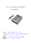
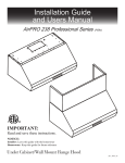
Package Contents (Fig.A)
Cross Actuation Assembly
(optional extra)
1
Motor B
25
24
3
5
2
Motor A
4
6
9
7
18
17
19
10
SNAPPER PIN
A3
14
SNAPPER PIN
13
A3
15
8
16
20
11
12
22
21
23
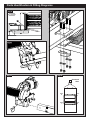
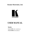
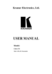
Parts Identification & Fitting Diagrams
Fig.1
A
C
B
Fig.2
Fig.3
B
H
B
A
F
D
E
81/(6627+(5:,6(63(&,),('
',0(16,216$5(,10,//,0(7(56
685)$&(),1,6+
72/(5$1&(6
/,1($5
$1*8/$5
1$0(
'(%85$1'
%5($.6+$53
('*(6
),1,6+
C
G
'$7(
6,*1$785(
'5$:1
'21276&$/('5$:,1*
5(9,6,21
F
7,7/(
&+.
'
$339
'
0)*
A
D
4$
E
G
0$7(5,$/
':*12
:(,*+7
C
WRSYLHZ
6&$/(
6+((72)
Fig.5
Fig.4
185mm
(min)
2.8mm to 3.5mm
165mm
(min)
30mm to 45mm
A
85mm (min)
1800mm to 2500mm (max)
Fig.6
Fig.7
B
Caravan Floor
A
L – Profile
U – Profile
Parts Identification & Fitting Diagrams
Fig.8
Fig.9
EM4445
A
10mm
Fig.10
Fig.11
Fig.12
Overhead
View
Motor
B
Motor
A
Motor
A
Motor
B
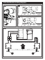
Parts Identification & Fitting Diagrams
Fig.14
Fig.13
20mm
Disengaged
Position
Fig.15
A
Engaged
Position
Fig.16
4 3 2 1
-
+
+ 12V -
3
4
+
-
Caravan
Front
B
1
2
+
-
A
81/(6627+(5:,6(63(&,),('
',0(16,216$5(,10,//,0(7(56
),1,6+
'(%85$1'
%5($.6+$53
'21276&$/('5$:,1*
5(9,6,21
Optional Fitting Adapters
Additional chassis clamp adapters are available, as follows:
Low Profile Chassis Adapter Plates (Part No. CM-029)
If your chassis frame height is less than 140mm these plates must be fitted to lower
the assembly to provide the correct height of 185mm. Drilling of your chassis may be
required. Note: In some countries, the installation must be checked by a professional
technician in order to adhere to local regulations.
Narrow Gauge Chassis Adapters (Part No. CM-030)
These plates must be utilised if you have an AL-KO Vario III/AV chassis which has a
frame thickness of less than 2.8mm. These must be positioned behind the axle using
pre-drilled holes already available on the chassis; so your mover must be fitted behind
the axle.
16mm Spacers - 1 pair (Part No. CM-028)
Use spacers to lower the mover assembly if your chassis has a frame height of between
140 to 185mm. A maximum of 3 sets of spacers can be utilised to achieve correct frame
height of 185mm. A set of extended clamp bolts must be used in conjunction with these
spacers (Part No. 346-054).
Set of 8 M10 x 100 Bolts (Part No. CM-031)
Set of 8 extended clamp bolts for use with 16mm spacers (Part No. 346-051)
I Table of Contents
Package Contents (Parts List)
Page 1
Introduction
Page 2
Fitting Guidelines
Page 2
Specifications
Page 2
Installation Safety Guidelines
Page 2,3
Installation - Mechanical Components
Page 3,4
Installation - Electrical/Electronic Components
Page 4
Operation Safety Guidelines
Page 5
Operation - Set-Up
Page 5
Operation - Detaching/Attaching the Motors
Page 6
Operation - Engaging the Rollers
Page 6
Operation - Motor Units
Page 6
Operation - Remote Control Handset
Page 7
Operation - Electronic Control Unit
Page 7
Before First Use - Pairing the Handset and Control Unit(s)
Page 7,8
Using Your Caravan Mover with Quattro® Technology
Page 8
Operation - Getting Started
Page 8
Operation - Hitching and Unhitching
Page 9
Maintenance
Page 9
Trouble-Shooting
Page 9,10
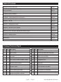
Package Contents (Fig.A)
Ref
Qty
Description
Ref
Qty
1
1
Motor Unit (B)
15
8
Chassis Clamp Washers 10mmØ
2
1
Motor Unit (A)
16
2
Chassis Stop Bolts & Nuts (2 pairs)
3
1
Cross Bar
17
4
Motor Unit Fixture Washer
4
1
Cross Bar
18
2
Motor Unit Fixture Bolt
5
1
Centre Cross Bar
19
2
Motor Unit Nylock Nuts
6
1
Carry Case inc. Motor & Battery Cables
20
1
Engagement Tool
7
1
Electronic Control unit
21
1
Motor Unit Extension Cable
8
1
Remote Control Handset
22
4
Cable Ties
9
2
Wire-Lock Pins
23
2
Roller Distance 20mm Spacers
10
2
Chassis U Plate
24
2
Cross Actuation Insert Bars
11
2
Upper Chassis Clamp Plate
25
1
Cross Actuation Centre Bar
12
2
Lower Chassis Clamp Plate
26
1
User Manual (not illustrated)
13
8
Chassis Clamp Nylock Nuts M10
27
3
AAA type 1.5V Batteries (not illustrated)
14
8
Chassis Clamp Bolts - M10x55
Ego®
Page 1
Description
Ref: EGO300-UM-1013-Rev.A
Introduction
Thank you for choosing an Ego® caravan mover. This has been produced according to very high standards and has
undergone careful quality control procedures. Simply by using the remote control you can move your caravan effortlessly
into any position required within operating guidelines.
Before proceeding with installation and starting to use the mover, please read this manual very carefully and be aware of
all the safety instructions! The owner of the caravan will always be responsible for correct use. Keep this manual inside
your caravan for future reference.
The caravan mover consists of two 12V motor-powered rollers, a 12V electronic control box and a remote control. To
function, the motor-powered rollers must be engaged against the tyres of your caravan. The optional cross actuation
device enables you to engage both rollers at the same time from one side of your caravan. Once this is done the mover
is ready for operation. The remote control will allow you to move your caravan in any direction.
Fitting Guidelines
The chassis clamps provided are suitable for fitment onto most standard caravan chassis that have an L-shape or
U-shape profile. Please refer to Fig.4 & Fig.6 for reference on dimensions and clearances BEFORE you proceed any
further with installation. If your chassis has different dimensions to those shown in Fig.4 then various chassis clamp
adapters are available to suit the majority of UK and Continental caravans; please refer to the section entitled ‘Optional
Fitting Adapters’.
Specifications
Model Number
EGO300
Operational Voltage
12 Volt DC
Average Current Consumption*
19 Ampere (approx)
Maximum Current Consumption*
84 Ampere (approx)
Speed
11cm per sec. (approx)
Approx. Net Weight (inc. all fixings & accessories)
40 Kg
Safe Working Load (SWL)
2250Kg
Minimum Width (caravan/trailer)
1800mm
Maximum Width (caravan/trailer)
2500mm
Power Source (battery)
12V
* Average Current Consumption readings when using an approx. 1100Kg single axle caravan on a hard, level surface.
* Maximum Current Consumption readings when using an approx. 1100Kg single axle caravan ascending a 1:4 (25%)
gradient.
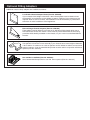
Installation Safety Guidelines
Important Safety Instructions
Read this User Manual carefully before installation and use. Failure to comply with
these rules could result in serious injury or damage to property.
These symbols identifiy important safety precautions.
They mean CAUTION! WARNING! SAFETY FIRST! IMPORTANT INFORMATION!
Ref: EGO300-UM-1013-Rev.A
Ego®
Page 2
Before starting installation under the caravan:
DO only use adapters and accessories that are supplied or recommended by the manufacturer.
DO check that the tyres are not over worn (fitting to new or nearly new tyres is the best option).
DO make sure that the tyre-pressures are correct to the manufacturer’s recommendation.
DO make sure the chassis is in good condition without any damage and is free from rust, dirt etc.
DO stop work immediately if you are in doubt about the assembly or any procedures and consult one of our engineers
DO NOT remove, change or alter any parts of the chassis, axle, suspension or brake mechanism.
DO NOT operate the unit if you are under the influence of drugs, alcohol or medication that could impair your ability to
use the equipment safely.
Installation - Mechanical Components
These instructions are for general guidance. Installation procedures may vary depending on caravan type.
Use appropriate support! Working under a vehicle without appropriate support is extremely dangerous. If you are fitting the mover system yourself, it is advisable that the installation is conducted by two people, as the mover will need to be raised up to the bottom of the caravan’s chassis before the clamps can be installed.
Place the caravan on a hard, level surface. The use of a lifting ramp or an assembly pit is ideal for access and personal
safety.
Clean the area of your chassis where you need to mount all components to ensure a good fitting.
Unpack all the components and check for the presence of all parts (see Package Contents List).
Make sure the caravan is prepared for installation. Check before installation that important areas, such as drains/spare
tyre etc. do not cause any obstruction to the function of the mover.
Ensure both rollers are in the DISENGAGED position (Fig.14), as the unit will not fit correctly otherwise
Loosely assemble cross bar (3), cross bar (4) and the centre cross bar (5). The nuts (Fig.1B), on each cross bar (3&4)
must be no more than finger-tight at this stage.
Place the assembly loosely under the caravan. In principle, the unit should be fitted in front of the caravan road wheels,
but if fitting in this position is not possible, it is permissible to fit it to the rear of the wheels by rotating the whole
assembly by 180° degrees.
Loosely fit the two clamping assemblies to the chassis (see Fig.9) and attach using the bolts, nuts and washers
(13,14,15) provided in the installation kit. Nuts must be no more than finger-tight.
Make sure that the Centre Cross Bar (5) is positioned in the middle of the caravan/mover (the centre of the bar is
marked).
With the main assembly loosely fitted onto the chassis, slide each motor unit (1&2) onto each end of the cross bar
assembly and secure using either the wire-lock pins (9) or, if you do not have the requirement to detach the motors
everytime you use the mover system then secure the motors using the bolts (18), washers (17) and Nylock Nuts (19).
With the main assembly loosely fitted onto the chassis, slide the whole assembly along the chassis until the rollers
(Fig.2A) are 20mm away from the surface of the centre each tyre (Fig.14). Two 20mm spacers (23) are provided.
It is vitally important that each roller is at exactly the same distance away from the tyre. The whole Ego®
Page 3
Ref: EGO300-UM-1013-Rev.A
assembly must be parallel to the caravan/trailer axle.
Loosen the locking bolts (Fig.1B) to enable you to slide the motor units in or out of the centre cross bar (5) accordingly
to ensure each roller will have the maximum possible contact with the tread of the tyre. Ensure that the position of each
motor unit does not obstruct shock absorbers (if fitted) and that the gear housing (Fig.2F) has a minimum distance of
10mm to the inner surface of the tyre when the mover is engaged (Fig.8).
Fully tighten the four nylock nuts (13) on both clamping assemblies (Fig.9) to a torque setting of 40 ft lbs/55Nm, then the
four bolts (Fig.1B) on the Cross Bars (3&4) to a torque setting of 9ft lbs/12Nm. Re-check the distance of 20 mm from the
rollers to the tyres and if necessary, loosen the bolts and re-adjust the position of the assembly.
If fitted the bolts that secure each motor unit should be tightened to a torque setting of 27ft lbs/37Nm.
Once satisfied with the position of the assembly, fit and tighten the Chassis Stop Nuts & Bolts (16) , one pair in each of
the Upper Chassis Clamp Plates (see Fig.9). Tighten to a torque setting of 40 ft lbs/55Nm. The Stop Bolts grip the lip
of the chassis and help prevent the mover from sliding along the chassis. The main mechanical components have now
been installed.
Optional Cross Actuation Bar
Assemble the parts of the cross actuation bar (24 & 25) and connect them to the motor units (1 & 2) with the nylock nut
and bolt (factory fitted) onto the cross actuation bar-connectors (see Fig.1A). Tighten the four bolts (Fig.1C) on the Cross
Actuation assembly (24 & 25) to a torque setting of 9ft lbs/12Nm
Installation - Electrical/Electronic Components
All the electrical components are pre-wired with weatherproof two-pole plug connectors.
Each motor unit has a plug connector secured to the top which are pre-wired to the positive (+) and negative (-)
terminals of the motors.
The supplied carry case (6) contains the electronic control unit (7) which is also pre-wired. The cable that attaches to
both motors is spooled around the cable storage hooks on the lid of the case. The motor cable is a four-core cable that
splits into two connectors, one for each motor.
The battery cable is also pre-wired to the Control Unit (7) and is stored in the same manner as the motor cable.
The motor connections are pre-configured for installation of the motors in FRONT of the wheels/axle (see Table A).
Please refer to table B (below) for fitment of the motor units to the REAR of the axle. Note: If you are fitting two sets of
motors onto a twin-axle caravan to form a full Quattro® system then both Table A & Table B wiring will be utilised. Please
refer to Fig.21.
A motor cable extension (21) is supplied so that both motors can be plugged in on one side of the caravan/trailer. When
installing the cross bar it needs to be determined which side is most convenient for you to plug into the motors. In
normal circumstances, during operation, the carry case containing the electronics and cables would be located in the
doorway of your caravan or in an externally accessible locker. The motor cable extension should be connected to the
plug on top of the motor on the opposite side to where you want to be able to access both motor plugs and should be
cable-tied to the cross bar assembly. That means that when you connect both motors to the Control Unit it can be done
from just one side for convenience.
Please refer to the wiring schematic to determine the correct configuration as the plug connectors for motor A and B
are colour coded. The wiring schematic (Fig.16) shows the configuration for front of axle fitting with the Extension Cable
(21) connected to locate both motor plug connectors on the left hand side of the caravan. If you require the motor plug
connectors to be located on the right hand side then you must swap the connections of the spade connectors on the
Control Unit (7) in accordance with Table.B.
Table . A
Table . B
REAR OF AXLE FITTING
Motor A Positive (+) cable to terminal 4
Motor A Negative (-) cable to terminal 3
Motor B Positive (+) cable to terminal 2
Motor B Negative (-) cable to terminal 1
FRONT OF AXLE FITTING
Motor A Positive (+) cable to terminal 1
Motor A Negative (-) cable to terminal 2
Motor B Positive (+) cable to terminal 3
Motor B Negative (-) cable to terminal 4
Ref: EGO300-UM-1013-Rev.A
Ego®
Page 4
Operation - Safety Guidelines
Before use, always check the mover for any damage.
When towing or moving the caravan please be aware, at all times, that ground clearance is reduced by 50mm when the Mover has been fitted.
To maintain signal strength, always make sure that, during manoeuvring, the distance between the remote control and the caravan does not exceed 5 metres.
DO be aware that the mover increases your caravan or trailer weight. So this reduces the payload of the caravan.
DO always make sure that the rollers are fully disengaged from the tyres when the mover is not in use. This is better for the tyres and for the mover.
DO always make sure that the rollers are fully disengaged before towing/moving the caravan by vehicle or manpower. This can damage the tyres, mover and the towing vehicle.
DO always make sure that the remote control is stored in a safe place (out of reach of children or other unauthorised people).
DO always apply the handbrake after manoeuvring, before disengaging the drive rollers from the tyres.
DO always ensure that children and pets are kept well out of the way during operation.
DO NOT rely on the mover to act as a brake.
DO NOT exceed the total Safe Working Load (SWL).
DO NOT make any modifications on the caravan mover (mechanical or electronically). This can be very dangerous! No warranty claim will be accepted and we cannot guarantee the function of the mover if any modifications are made. We will not be liable for any damage whatsoever caused as a result of incorrect installation, operation or modification.
Operation - Set-Up
Before you use your mover system you need to locate the Carry Case (6) that contains the Control Unit (7) and cables in
the caravan doorway or in an externally accessible locker.
First, unwind the motor cable and connect both motor plug connectors onto both motors (the plug connectors are colour coded). Please refer to Fig.16.
Safety First! Only unwind the minimum amount of cable that is required between the motors and the Carry Case as it is important that the cable cannot get caught on any moving parts or does not drag on the ground. The cable between the motors and the control unit should be taut but not overtight in order to avoid straining any plug connectors.
You can then unwind the battery cable from the Carry Case and connect to your 12V battery power source.
Caution! Make sure that you do not reverse the Positive (+) and Negative (-) connections. Incorrect connection (reverse polarity) may result in damage to the Control Unit.
Ego®
Page 5
Ref: EGO300-UM-1013-Rev.A
Operation - Detaching/Attaching the Motors
The motor units are designed to be easily attached/detached if you do not wish for them to remain in position during
transit or if you only envisage yourself using the mover system at your home rather than during your holiday.
If you have opted for temporary fitment then each motor must be fitted onto the cross bar before operation.
Locate the appropriate side motor (1 or 2) and slide onto each end cross bar (3&4) then secure into position by inserting the wire-lock pins (9). You must ensure that the pin is locked in place with the spring wire fully locked. Please refer to
Fig.10 and Fig.11 for reference.
Engaging the Rollers
In order to engage the rollers, fit the end socket of the Engagement Tool (20) on the spindle (Fig.2G) on the right or left
drive unit.
Position the engagement tool parallel to the ground, then rotate the tool through approximately 180° degrees.
Note: to engage the rollers you always rotate the tool towards the tyre, irrespective of which side you are operating the
engagement from.
The engagement mechanism utilises a simple over-centre cam that pushes the rollers onto the tyres and then locks into
place automatically. If the mover has been installed correctly, at exactly 20mm away from the tyres when disengaged,
the amount of force provided onto the tyre by the roller will be sufficient for most circumstances of use (Fig.15).
To disengage the rollers, simply refit the tool onto one of the spindles and rotate away from the tyre. Please note that you
will feel a small amount of resistance initially as you disengage the cam from its locked position; the spring will then do
the rest of the work and pull the roller away from the tyre and into the fully disengaged position (Fig.14).
Operation - Motor Units
The mover has two Motor Units (1 & 2). In general they are mounted in front of the axle of the caravan/trailer. Both units
are identical but cannot be switched. Please refer to Fig.2
Fig.2
A:
B:
C:
D:
E:
F:
Drive roller
12V Motor
Connection Terminals (+ and -)
Base Unit
Drive Unit
Gear Housing
Always ensure that you are close enough to engage the caravan’s handbrake when manoeuvring on
uneven terrain and gradients/slopes in case of mechanical failure. Do not use the mover as a brake, when you have finished manoeuvring always engage the caravan’s handbrake.
SAFETY FIRST! Ensure that there are no persons or obstructions in the vicinity of the caravan prior to testing.
Ref: EGO300-UM-1013-Rev.A
Ego®
Page 6
Operation - Remote Control Handset
The Remote Control handset (8) is powered by three ‘AAA’ 1.5V batteries, and is activated by double-pressing the power
button (Fig.3A). Once activated the green LED (Fig.3H) will illuminate and the directional controls can now be used. If the
handset has not been used for a period of 60 seconds then it will automatically switch itself off.
Fig.3
A = On (press button twice within one second, green LED (Fig.3H) illuminates)
B = Caravan forwards (both wheels rotate in forwards direction)
C = Caravan reverse (both wheels rotate in reverse direction)
D = Caravan left forwards (right wheel rotates in forwards direction)
E = Caravan right forwards (left wheel rotates in forwards direction)
F = Caravan left reverse (right wheel rotates in reverse direction)
G = Caravan right reverse (left wheel rotates in reverse direction)
In addition, the ‘left forward’ (3D) and ‘right reverse’ (3G) buttons or ‘right forward’ (3E) and ‘left reverse’ (3F) buttons
may be pressed at the same time to turn the caravan around on its own axis (without moving forward or backward).
Note: this function is disabled when the electronics are in twin-axle mode.
When pressing a directional button on the handset, the mover will start slowly, normal speed will be reached within 2.5
seconds.
Changing batteries in the remote control:
Open the rear cover of the handset by pushing gently and sliding the rear cover in the direction of the arrow (Fig.5). Take out the depleted/old batteries and dispose in the appropriate way (check with your local authority for correct disposal of batteries). Install new replacement batteries. Make sure to use leak proof batteries (No claims under guarantee can be considered for damage caused by leaking batteries).
Slide the rear cover on gently and it will click into place.
Operation - Electronic Control Unit
The Electronic Control Unit (7), which is mounted inside your caravan, is responsible for controlling the caravan mover.
The control unit has three LED’s (Fig.7) and one recessed button (Fig.7A):
Green LED – Blue LED – This will illuminate when receiving the signal. The LED will flash if the remote control is out of range (the maximum range is 100 metres – without obstruction).
This will illuminate if the temperature of the control unit is too high, or if the battery voltage is
too low or too high.
The Red LED will specify the error as follows:
Red LED – Voltage too low <10V: LED will flash twice slowly.
Voltage too high >15V: LED will flash fast 5 times.
Electric current is too high (≥120A): LED will constantly flash.
Temperature is too high >80C: LED is on permanently.
Reset Button (Fig.7A) – This only needs to be used when replacing a remote control handset. Refer to the ’Before First
Use - Pairing the Handset and Control(s)’ section for reference on this procedure.
When the Control Unit is connected to power, it will perform a self-test automatically. The 3 LEDs will illuminate for 0.2
seconds, and turn off, which means there is no error and the unit is functioning correctly.
As a safety feature the Control Unit will switch off automatically if no button is pressed within 60 seconds. The Control
Unit will also turn off automatically if the mover is working constantly in one direction for longer than 3 minutes.
Before First Use - Pairing the Handset and Control Unit(s)
Install only 2 of the 3 ‘AAA’ batteries into the battery compartment of the Handset (see Fig.5A).
Press the Reset button (Fig.7A), the green LED will flash (press the reset button on both Control Units when using a full
four-motor Quattro® system).
Ego®
Page 7
Ref: EGO300-UM-1013-Rev.A
Hold down the corresponding button on the Handset (Fig.3E for Single Axle Mode or Fig3.G for Twin-Axle Mode) and,
at the same time, install the third battery. Note: Twin-Axle Mode is used for twin-axle caravan installations that use two or
four motors.
The Handset will sound single beeps (for Single Axle Mode) or double beeps (for Twin-Axle Mode).
Keep holding the button down until the Handset stops beeping and the green LED(s) (Fig.2C) on the control unit(s) turn(s)
off.
The control unit(s) will switch off.
Press the power button on the handset (Fig.3A) twice. The Control Unit(s) will make a clicking noise to indicate the system
is operational.
The pairing procedure is now complete and the caravan mover system is ready for use.
Using your Caravan Mover with Quattro® Technology
It is, of course, impossible for a twin-axle caravan to be manoeuvred in the same way as a single-axle as the turning
circle is greatly increased compared to a single-axle caravan. Also, the amount of different manoeuvres required to
locate/park your caravan is increased.
However, the advanced electronics of the Quattro® electronics take care of the manoeuvring whilst also taking care of
your caravan.
For example:
When the caravan is turning, the motors provide lower rotational speed on one side to help enable direction
change. This enables the caravan to manoeuvre with minimal tyre ‘scrub’ or being dragged along the ground,
which can cause undue stresses on its tyres, wheel hubs and chassis.
It is also a possibility that when operating a two motor twin-axle system, on very uneven ground, one of the wheels
driven by the mover will not make adequate contact to continue progress. If this occurs, you will need to move the
caravan in a different direction until adequate traction is regained.
Operation - Getting Started
Please make sure you read the safety instructions very carefully and make sure that you follow these guidelines!
Make sure that the battery that supplies the mover is fully charged and in good condition.
Make sure that the caravan is free from the vehicle and the handbrake is on. Also make sure that the corner-
steady feet are fully raised.
Engage both rollers as described in ‘Operation-Motor Units’. This only needs to be done on one side of your caravan
since the other side will automatically follow via the cross actuation bar.
Before operating the Mover, release the handbrake.
Activate the mover by double-clicking the power button (Fig.3A) on the remote control. The LED (Fig.3H) on the remote
control will illuminate. Now you can choose the movements according the symbols shown on the remote control
As soon as the buttons are released the caravan will stop
The mover moves at one speed after the intitial ‘soft-start’. The speed can increase a little when going downhill and
decrease a little when going uphill. TIP: The mover is more efficient when reversing the caravan up an incline.
After manoeuvring, deactivate the mover by double-clicking the power button on the remote control again. The LED on
the remote control will turn off. Apply the handbrake first and then disengage the drive rollers from the tyres.
Store remote control in a safe place (out of reach of children or other unauthorised people).
Ref: EGO300-UM-1013-Rev.A
Ego®
Page 8
Operation - Hitching and Unhitching
It is possible to position the caravan’s hitch exactly over a stationery car’s tow ball using the mover. But please be very careful!
Use the button controls on the remote control to bring the caravan to the car. It is better to reach the tow ball with
several short “trips” rather than trying to do it in one “trip”. When the hitch is right above the tow ball of the vehicle,
lower the hitch to the ball and engage in the normal way using the jockey wheel.
Hitch the caravan in the normal way ready for towing.
Release the rollers from the caravan’s tyres. You cannot tow the caravan with the Mover engaged! Make sure that both rollers are fully disengaged!
Trying to drive away with the mover still engaged, will damage the mover, your caravan tyres and strain your tow vehicle!
Maintenance
To prevent the battery from becoming totally discharged during long periods of inactivity it must be disconnected and
recharged before using again.
Please check regularly that the rollers of the drive units are free of any dirt, or debris that may have been picked up from
the road. Any further maintenance is not required.
Please check regularly the distance between the rollers and the tyres. In the neutral (fully disengaged) position this must
be 20 mm.
When your caravan is stored for an extended period of time (over winter for example) it is recommended to remove the
battery from the caravan. Make sure you keep it charged to ensure it is in good condition the next time you want to use
it.
Once a year have your Ego® caravan mover maintained and visually inspected. This inspection must include all the bolt/
nut connections, the cables and electrical connections and lubrication of movable parts/joints.
In case of any failures or problems, please contact your Ego® Caravan Mover supplier.
Trouble Shooting
Should your mover fail to operate, please check the following:
Unit fails to operate, does not function at all:
Is the Remote Control Handset ‘paired’ with the Control Unit? To ‘pair’ the Handset and Control Unit please follow the
procedure detailed in the section ‘Before First Use - Pairing the Handset & Control Unit(s)’ regarding the Reset Button
(Fig.7A).
Check the batteries of the remote control. If empty, renew using three new ‘AAA’ 1.5V batteries.
Caravan battery could be empty. Check electronics box (Blue LED is on and Red LED is flashing twice slowly). If empty,
recharge completely or renew caravan battery before taking any further action.
Advice on battery voltage: Even though batteries are rated at 12V, a fully charged battery will provide a charge nearer
to 13V (depending on battery type). A voltimeter reading of 12.7V or higher means that the battery is 100% charged,
12.5V is three quarters charged and 12.4V can mean your battery is only 50% charged. The caravan mover needs at
least 12.5V to function correctly.
Mover power source battery could be overloaded. Check electronics box (Blue LED is on and Red LED is flashing
continuously). Check your charging equipment and try to discharge the battery by connecting/using a light or other load.
If this does not give any result, renew caravan battery before taking any further action.
Check the cable-connection between the mover battery and the control unit.
Ego®
Page 9
Ref: EGO300-UM-1013-Rev.A
Trouble Shooting
Check the distance between the remote control and the caravan is not more than 5 metres. If there is no signal between
the remote control and the control unit, the mover will not function at all, even though the LED on the remote control is
on.
All error messages will reset automatically after 40 seconds. If this does not occur, reset the mover by disconnecting the
mover power source battery for at least 10 seconds and reconnect. Then re-establish the connection with the remote
control (by pressing the power button on the handset twice within 1 second).
Unit fails to operate or moves intermittently:
Check the battery of the remote control. If empty, renew using three new ‘AAA’ 1.5V batteries.
Mover battery could be empty. Check electronics box (Blue LED is on and Red LED is flashing twice slowly). If empty,
recharge completely or renew mover battery before taking any further action.
Mover battery could be low - with the rollers engaged. Check the voltage drop on the caravan battery meter, if this
immediately drops well below 10 volts, charge or renew mover battery.
Mover battery could be overloaded. Check electronics box (Blue LED is on and Red LED is flashing continuously). Check
your charging equipment and try to discharge the battery by connecting/using a light or other load. If this does not give
any result, renew mover battery before taking any further action.
Check the cable-connection between the mover battery and the control unit.
Badly connected or corroded battery terminals can cause intermittent problems, check battery terminals, clean and
connect again.
Check the distance between the remote control and the caravan is not more than 5 metres. If there is no signal between
the remote control and control box, the mover will not function at all, even though the LED on the remote control is on.
All error messages will reset automatically after 40 seconds. If this does not occur, reset the mover by disconnecting the
mover power source battery for at least 10 seconds and reconnect. Then re-establish the connection with the remote
control (by pressing the power button on the handset twice within 1 second).
Rollers slip on wheels:
Check that the distance of the rollers to the tyres is 20mm on both sides. Check for correct tyre pressure by referring
to your caravan mnaufacturer’s handbook. If the pressure is low, the roller would need to be pushed into the tyre further
than usual to gain sufficient traction.
In case of any doubt, please call your Ego® Caravan Mover supplier.
Ref: EGO300-UM-1013-Rev.A
Ego®
Page 10