1
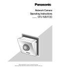
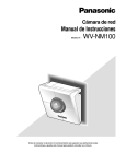
Network Camera
Operating Instructions
Model No.
WV-NM100
Before attempting to connect or operate this product,
please read these instructions carefully and save this manual for future use.
ENGLISH VERSION
Caution:
Before attempting to connect or operate this product,
please read the label on the bottom.
CAUTION
RISK OF ELECTRIC SHOCK
DO NOT OPEN
CAUTION: TO REDUCE THE RISK OF ELECTRIC SHOCK,
DO NOT REMOVE COVER (OR BACK).
NO USER-SERVICEABLE PARTS INSIDE.
REFER SERVICING TO QUALIFIED SERVICE PERSONNEL.
SA 1965
The lightning flash with arrowhead symbol,
within an equilateral triangle, is intended to
alert the user to the presence of uninsulated
"dangerous voltage" within the product's
enclosure that may be of sufficient magnitude to constitute a risk of electric shock to
persons.
The exclamation point within an equilateral
triangle is intended to alert the user to the
presence of important operating and maintenance (servicing) instructions in the literature accompanying the appliance.
SA 1966
Power disconnection. Unit with or without
ON-OFF switches has power supplied to the
unit whenever the power cord is inserted
into the power source; however, the unit is
operational only when the ON-OFF switch is
in the ON position. Unplug the power cord
to disconnect the main power for all unit.
For U.S.A
NOTE: This equipment has been tested and found to comply with the limits for a Class B digital device, pursuant to
part 15 of the FCC Rules. These limits are designed to provide reasonable protection against harmful interference in a
residential installation.
This equipment generates, uses and can radiate radio frequency energy and, if not installed and used in accordance
with the instructions, may cause harmful interference to
radio communications. However, there is no guarantee that
interference will not occur in a particular installation. If this
equipment does cause harmful interference to radio or television reception, which can be determined by turning the
equipment off and on, the user is encouraged to try to correct the interference by one or more of the following measures:
– Reorient or relocate the receiving antenna.
– Increase the separation between the equipment and
receiver.
– Connect the equipment into an outlet on a circuit different
from that to which the receiver is connected.
– Consult the dealer or an experienced radio/TV technician
for help.
FCC Caution: To assure continued compliance, (example use only shielded interface cables when connecting to computer or peripheral devices). Any changes or modifications
not expressly approved by the party responsible for compliance could void the user’s authority to operate this equipment.
The serial number of this product may be found on the bottom of the unit.
You should note the serial number of this unit in the space
provided and retain this book as a permanent record of your
purchase to aid identification in the event of theft.
Model No.
WV-NM100
Serial No.
WARNING: To prevent fire or electric shock hazard, do not expose this appliance to rain or moisture. The apparatus shall not be exposed to
dripping or splashing and that no objects filled with liquids, such as vases, shall be placed on the apparatus.
2
IMPORTANT SAFETY INSTRUCTIONS
1) Read these instructions.
2) Keep these instructions.
3) Heed all warnings.
4) Follow all instructions.
5) Do not use this apparatus near water.
6) Clean only with dry cloth.
7) Do not block any ventilation openings. Install in accordance with the manufacturer's instructions.
8) Do not use near any heat sources such as radiators, heat registers, stoves, or other apparatus (including amplifiers) that produce heat.
9) Do not defeat the safety purpose of the polarized or grounding-type plug. A polarized plug has two blades with
one wider than the other. A grounding-type plug has two blades and a third grounding prong. The wide blade or
the third prong are provided for your safety. If the provided plug does not fit into your outlet, consult an electrician
for replacement of the obsolete outlet.
10) Protect the power cord from being walked on or pinched particularly at plugs, convenience receptacles and the
points where they exit from the apparatus.
11) Only use attachments/accessories specified by the manufacturer.
12) Use only with the cart, stand, tripod, bracket, or table specified by the manufacturer, or sold with the apparatus.
When a cart is used, use caution when moving the cart/apparatus combination to avoid injury from tip-overs.
S3125A
13) Unplug this apparatus during lightning storms or when unused for long periods of time.
14) Refer all servicing to qualified service personnel. Servicing is required when the apparatus has been damaged in
any way, such as power-supply cord or plug is damaged, liquid has been spilled or objects fallen into the apparatus, the apparatus has been exposed to rain or moisture, does not operate normally, or has been dropped.
3
CONTENTS
PREFACE ....................................................................................................................... 6
FEATURES ................................................................................................................ 6
PRECAUTIONS .............................................................................................................. 7
PLATFORM ............................................................................................................... 8
TRADEMARKS AND REGISTERED TRADEMARKS .............................................. 9
DOCUMENT CONVENTION ..................................................................................... 9
MAJOR OPERATING CONTROLS AND THEIR FUNCTIONS ...................................... 10
Front View ................................................................................................................. 10
Rear View .................................................................................................................. 10
INSTALLATIONS ............................................................................................................ 11
CONNECTIONS.............................................................................................................. 12
Connection between a PC and This Camera (Connection type 1) ............................ 12
Using with an Intranet (LAN) (Connection type 2) ..................................................... 13
Using via Internet (Connection type 3-4) ................................................................... 14
SETUP ............................................................................................................................ 15
Preparations for the Setup ........................................................................................ 15
Setup with the Provided "Panasonic IP Setup" Software .......................................... 16
Network Setup of the PC ........................................................................................... 18
Using Windows 98 SE................................................................................................ 18
Using Windows 2000 ................................................................................................. 20
Using Windows XP (Category View) ......................................................................... 22
Network Setup of the Camera ................................................................................... 24
Parameters for the “Network setup” Items Depending on the Connection Type ....... 27
Installation of the MPEG-4 Plug-in ............................................................................ 29
Basic Settings ............................................................................................................ 30
BROWSING PICTURES ................................................................................................. 32
Monitoring a Still Picture of a Single Camera ............................................................ 32
Monitoring the Motion Picture of a Single Camera .................................................... 34
Monitoring Still Pictures of Multiple Cameras ............................................................ 36
Monitoring the Picture of a Camera in a Preset Position ........................................... 39
Saving the Currently Monitored Picture on the PC .................................................... 41
DETECTING MOTION IN THE MONITORED AREA...................................................... 42
Motion Detector Function .......................................................................................... 42
Action when Motion is Detected ................................................................................ 42
Settings of the Actions to be Performed when Motion is Detected ........................... 43
Items on the “Alarm” page.......................................................................................... 45
Setting of the Motion Detection Area ......................................................................... 46
Viewing the Picture Stored in the Camera ................................................................ 48
TRANSFERRING PICTURES TO THE SERVER........................................................... 49
Preparations for Transferring Pictures to the Server ................................................. 49
Transferring Pictures to the Server at Designated Intervals ...................................... 51
Transferring Pictures to the Server when Motion is Detected ................................... 52
OTHER FUNCTIONS...................................................................................................... 53
Alarm Connector and AUX Output Connector ........................................................... 53
Customizing the Contents of the Alarm Mail ............................................................. 53
4
ADVANCED SETTINGS ................................................................................................. 54
Advanced Settings for “Operation mode” .................................................................. 54
Adjusting the Picture ................................................................................................. 56
Settings for the Host Authentication .......................................................................... 58
Settings for the User Authentication .......................................................................... 60
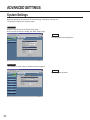
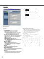
System Settings ........................................................................................................ 62
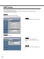
SNMP Settings .......................................................................................................... 65
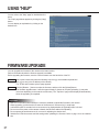
USING “HELP” ............................................................................................................... 67
FIRMWARE UPGRADE ................................................................................................. 67
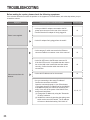
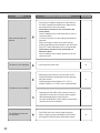
TROUBLESHOOTING .................................................................................................... 68
SPECIFICATIONS .......................................................................................................... 71
GLOSSARY OF TERMS ................................................................................................. 72
5
PREFACE
This is a camera that can be connected to a network.
You can view camera pictures with the web browser on a personal computer (PC), by connecting this camera to
networks such as a LAN or the Internet.
FEATURES
This camera offers you the following features:
● You can use it with the web browser of a PC.
You can view camera pictures, set up preferences for the camera and operate the camera with the web browser of
a PC just by connecting the camera to a network.
Note: Setting of the network environment is required depending on the PC.
● You can view still pictures and motion pictures.
You can view the camera picture as a still picture (JPEG) or a motion picture (MPEG-4). You can display or stop the
camera picture with the web browser.
Note: To monitor motion pictures (MPEG-4), it is necessary to install the plug-in provided onto the web browser.
● You can simultaneously view camera pictures from multiple cameras on a single monitor
screen.
You can display still pictures from up to four cameras on a single monitor screen.
● You can specify operations in case movement is detected in the area under surveillance.
When movement is detected in the area under surveillance, you can specify operations such as storing images,
sending automatic e-mails, etc.
● You can set limitations for users.
By setting user names and passwords in advance, you can limit unregistered users to view camera pictures. You
can also specify the operating level for each user, such as limiting the user's authority to operate the camera, to perform the settings, etc.
6
PRECAUTIONS
● Refer all work related to the installation
of this product to qualified service
personnel or system installers.
● Do not operate the appliance beyond its
specified temperature, humidity, or
power source ratings.
Use the appliance at temperatures within 0 °C - +
40 °C (32 °F - 104 °F) and humidity below 90 %.
The input power source for this appliance is 120 V
AC 60 Hz.
● Handle the appliance with care.
Do not strike or shake, as this may damage the
appliance.
● Do not aim the camera at bright light
sources.
If a bright light, such as a spotlight, is present on
the monitor screen, blooming (blurring around
areas with excessive brightness) or smearing
(appearance of vertical lines above and below a
bright object) may occur.
● Only use the camera indoors.
Do not install it in places where the camera is
exposed to sunlight for long periods of time or near
air conditioning equipment. This will cause deformation, discoloration, breakdown or malfunction.
● Only use the AC adapter provided with
this camera to connect to the power
source.
Do not plug it into an outlet also hosting big appliances with high power consumption (such as a
copy machine or an air conditioning unit).
● Do not touch the dome cover directly.
Dirt on the dome cover may decrease the quality of
the picture.
Hold it by its sides when you move the camera.
● Do not strike or give a strong shock to
the camera.
It may cause damage or allow water to enter the
camera.
● Built-in backup battery
Before the first use, charge the built-in backup battery by turning on the power for 48 hours or more.
If it is not charged enough, in the case where the
power goes down, the internal clock may keep bad
time or the operative condition may be different to
that before the electric power failure.
The built-in battery life is approximately 5 years.
Ask the shop where you purchased the camera
when replacement of the battery is required.
● Cleaning
Turn the power off when cleaning the camera.
Otherwise it may cause injuries.
● Do not use strong or abrasive detergents
when cleaning the appliance body.
Use a dry cloth to clean the appliance when it is
dirty.
When the dirt is hard to remove, use a mild detergent and wipe gently.
● To obtain clear images
Clean the dome cover approximately once a month
to obtain clear images.
● PC monitor
Displaying the same image for a long time on the
monitor screen may damage the monitor screen. It
is recommended that a screen saver be used.
● Broadband Router
If the camera is connected via the Internet with a
router, use a broadband router with address translation (NAT or IP masquerade). Refer to the operating instructions of the broadband router for the
description of the address translation.
● Restart automatically when an error is
detected.
The camera restarts automatically when an error is
detected for any reason. You cannot operate the
camera for approximately two minutes after the
restart until the initialization has been completed,
as happens when the power is turned on for the
first time.
● We recommend that you note down your
settings and save them. Power or battery
failure may erase the settings you
entered.
7
PRECAUTIONS
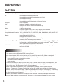
PLATFORM
Setting up and operating this camera is possible with PCs meeting the system requirements described below.
Microsoft® Windows® 98 Second Edition
Microsoft® Windows® 2000 Professional Service Pack 2
Microsoft® Windows® Me
Microsoft® Windows® XP
Microsoft® Windows NT® Workstation 4.0 Service Pack 6a
Computer:
PC/AT Compatible
CPU:
Pentium® II (300 MHz or higher) for still pictures
Pentium® III or faster for motion pictures (MPEG-4)
Memory:
128 MB or more
Monitor:
24-bit True color or better
Required to support XVGA (1024 x 768) or higher picture resolution
Network Interface:
10/100Mbps Ethernet® board must be installed
Compatible Network Protocols: TCP/IP, UDP/IP, HTTP, FTP, SMTP, RTP, DNS, DDNS, DHCP, ARP, BOOTP, NTP
and SNMP
Browser:
Internet Explorer 5.5, 5.5SP2, 6.0
Netscape Communicator® 4.73, 4.78
The MPEG-4 plug-in is exclusive to Internet Explorer.
It cannot be used for Netscape Communicator.
Adobe® Acrobat® Reader®:
Required to browse the operating instructions on the CD-ROM. If Acrobat® Reader®
is not installed on the PC, download the latest version of Acrobat® Reader® from the
Adobe Systems Incorporated web site and install it.
CD-ROM Drive:
Required to install the MPEG-4 plug-in software and browse the operating instructions on the CD-ROM.
OS:
! Important
• This camera does not support Netscape 6.x currently released.
• This camera does not support the PPPoE network protocol.
• When browsing still pictures and motion pictures with Internet Explorer, select [Tool] – [Internet options] to display “Internet Options”, then click the [Security] tab and press the [Custom Level…] button to display the
[Security Setting] window. And then, check “Enable” for the following:
• Script ActiveX controls marked safe for scripting
• Run ActiveX controls and plug-ins
• Active scripting
• To perform the settings for the proxy server, select [Tool] – [Internet options] to display “Internet Options”, then
press the [LAN Settings…] button to display the [Local Area Network (LAN) settings] window. And then, check
“Use a proxy server” and “Bypass proxy server for local addresses”.
• When using Internet Explorer, select [Tool] – [Internet options] to display “Internet Options”. Press the
[Settings…] button in the “Temporary Internet files” area on the [General] page to display the [Settings] page.
And then, check “Every visit to the page”. When using Netscape Communicator 4.7x, select [Edit] – [Preferences]
to display the [Preferences] window. Click [Advanced] - [Cache], and check “Every time” for “Document in cache
is compared to document on network”.
• Cookie is accepted when the camera accesses an HTML document. When using Netscape Communicator,
uncheck “Warn me before accepting a cookie.” Otherwise, an alert message will appear with every access.
8
TRADEMARKS AND REGISTERED TRADEMARKS
• Microsoft, Windows, Windows NT and Windows XP are registered trademarks of Microsoft Corporation in the
U.S. and/or other countries.
• Netscape, Netscape Navigator, Netscape ONE, the Netscape N and Ship's Wheel logos are registered trademarks of Netscape Communications Corporation in the U.S. and other countries. Other Netscape product names
used in this document are also trademarks of Netscape Communications Corporation and may be registered
outside the U.S.
• Ethernet is a registered trademark of Xerox Corporation.
• Other names of companies and products contained in these operating instructions may be trademarks or registered trademarks of their respective owners.
• Distributing, copying, disassembling, reverse compiling, reverse engineering, and also exporting in violation of
export laws of the Software provided with this product, is expressly prohibited.
DOCUMENT CONVENTION
The abbreviations below are used in this manual.
Windows 98 SE stands for Microsoft® Windows® 98 Second Edition.
Windows 2000 stands for Microsoft® Windows® 2000 Professional Service Pack 2.
Windows Me stands for Microsoft® Windows® Millennium Edition.
Windows NT stands for Microsoft ® Windows NT® Workstation 4.0 Service Pack 6a.
Windows XP stands for Microsoft® Windows® XP.
9
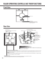
MAJOR OPERATING CONTROLS AND THEIR FUNCTIONS
Front View
Dome cover
Power LED
You can select ON or OFF for
the LED on the “System” page.
(Refer to page 63.)
Rear View
Connector cover
To detach the connector cover, hold down
the
part and slide it.
Alarm connector
Power plug connector
(Only use the AC adapter supplied)
Ethernet
connector
Link LED
(Lights up when
communication with
connected devices
becomes possible.)
Access LED
(Lights up when
accessing to the
network.)
Inside of the connector cover
! Important
Firmly insert the power plug of the AC adapter into the power plug
connector of the camera.
HTML document initialization switch
All HTML documents return to the default settings (to the default settings of the latest upgraded firmware if the firmware has been
upgraded) when the AC adapter is plugged into an outlet while this switch is pressed and kept pressed for five seconds or more
after the plug is inserted.
Note:
It will take around 5 minutes to initialize all HTML documents. The power LED blinks during the initialization. It changes to steady
light after the initialization has been completed.
Setting reset switch
All settings return to the default settings when the AC adapter is plugged into an outlet while this switch is
pressed and kept pressed for five seconds or more after the plug is inserted.
10
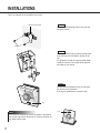
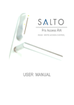
INSTALLATIONS
This is an example of an installation onto a wall.
STEP1
Wall-mounting bracket
Install the wall-mounting bracket onto the wall
using the screws.
Screws
STEP2
Install the camera onto the wall-mounting bracket by referring to the illustration shown on the
left.
It is possible to install the camera upside down.
Install the camera in the upside down position
according to your needs.
STEP3
Confirm that the Panasonic logo is in the position shown in the illustration.
If the logo is upside down, rotate the logo.
Logo
Note
If the camera is placed on a desk, as shown in the illustration on the right, select "Desk top" for "Camera position" on
the "Basic setup" page.
11
Logo
CONNECTIONS
Before starting the connections, confirm which type of connection meets your needs.
The following explanations are provided for each connection type.
Prepare the required hardware and cables for your connection type before starting the connections.
! Important
Before starting the connections, confirm that all the power switches of the camera, the ADSL/cable modem, the
switching hub and the PC are turned off, and that all power plugs are not connected to the outlet.
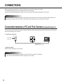
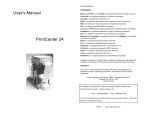
Connection between a PC and This Camera (Connection type 1)
Connect the camera and the PC directly using an Ethernet cable when browsing the camera pictures or performing
the network settings of the camera.
< Connection example >
AC adapter
To an outlet
(120 V AC)
Ethernet cable
(category 5 cross cable)
< Required cable >
Ethernet cable (category 5 cross cable)
! Important
• All cameras connected to the network must use their own exclusive AC adapter.
• Use only the specified Ethernet cable, category 5 cross cable.
12
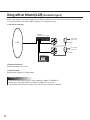
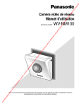
Using with an Intranet (LAN) (Connection type 2)
Connect the camera to an intranet (LAN) using an Ethernet switching hub or router when browsing camera pictures
of a camera installed in the same LAN (the intranet of a company or home).
< Connection example >
Ethernet
switching hub or router
To an outlet
(120 V AC)
LAN
AC adapter
To an outlet
(120 V AC)
AC adapter
< Required hardware >
Ethernet switching hub or router
< Required cable >
Ethernet cable (category 5 straight cable)
! Important
• Use an Ethernet switching hub or router suitable for 10Base-T/100Base-TX.
• Install also a LAN card suitable for 10Base-T/100Base-TX on the PC.
• All cameras connected to the network must use their own exclusive AC adapter.
13
CONNECTIONS
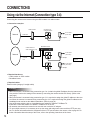
Using via the Internet (Connection type 3-4)
Connecting the camera to the Internet using an xDSL modem or a cable modem.
< Connection example >
Cable modem
Internet
Connection of
a single camera
To an outlet
(120 V AC)
Cable line
Connection
type 3
AC adapter
Broadband router
Cable modem or
xDSL modem (1 port)
To an outlet
(120 V AC)
Internet
Cable line
or xDSL
line
AC adapter
Connection
type 4
To an outlet
(120 V AC)
AC adapter
< Required hardware >
• Cable modem or xDSL modem
• Broadband router
< Required cable >
Ethernet cable (category 5 straight cable)
! Important
• When the camera is connected using connection type 3 or 4, obtain the global IP address from the Internet service provider. Perform the settings of the camera by connecting the camera and the PC directly. (Refer to the
next page.)
• When the camera is connected using connection type 3, it is required to assign the global IP address to the camera. When the camera is connected using connection type 4, it is required to assign the global IP address to the
broadband router and to set the address translation. (Refer to page 26.).
• Use an Ethernet switching hub or a broadband router suitable for 10Base-T/100Base-TX.
Install also a LAN card suitable for 10Base-T/100Base-TX on the PC.
• All cameras connected to the network must use their own exclusive AC adapter.
• To use multiple cameras, it is necessary to set up the router and assign each camera with an HTTP port number. For further information about the assignment of the HTTP port number to the camera, refer to page 28. For
further information about the setup of the router, refer to the operating instructions of the router.
14
SETUP
After completing the connections, it is necessary to set up the network of the PC and the camera.
To operate the camera connected in a network such as a LAN or the Internet, it is necessary to set up the network.
Use the provided "Panasonic IP Setup" software to set up the network of the camera. (Refer to the next page).
If the setup with the provided software fails, set up the PC and the camera separately. For further information, refer
to pages 18 - 28.
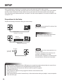
Preparations for the Setup
Prepare the following items before starting the network setup.
STEP1
Connect the camera and the PC in either of the
ways shown on the left.
Ethernet cable
(Category 5 cross cable)
Ethernet
switching hub
! Important
Use a category 5 cross cable if the camera
and the PC are connected directly.
Ethernet cable
(Category 5 straight cable)
AC adapter
To an outlet
(120 V AC)
STEP2
Turn on the power of the camera after the connection is made.
The power is supplied to the camera by connecting the AC adapter to an outlet.
After the power is supplied, it will take around 2
minutes before the camera can be operated.
Notes
• When the power is supplied, the power LED lights up for around 80 seconds and then blinks for around 20 seconds. Then the camera performs one complete panning and tilting operation.
• Confirm that the power LED and the link LED are lit after the power is supplied.
If the power LED is not lit:
Confirm that the AC adapter is firmly plugged into both the camera and the outlet.
If the link LED is not lit:
Confirm that the Ethernet cable is inserted firmly. Confirm also that the cable type (straight / cross) corresponds
to the connection type.
15
SETUP
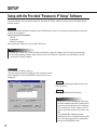
Setup with the Provided "Panasonic IP Setup" Software
Set up the network of the camera by using the "Panasonic IP Setup" software included on the CD-ROM provided
with the camera.
STEP1
When the provided CD-ROM is inserted into the CD-ROM drive of the PC, the launcher software starts up and the
readme file is displayed.
Items included in the software
• SETUP
• Instructions
• MPEG-4 Installation
After reading the readme file, click the [SETUP] button.
Notes
• Double click "launch.exe" on the provided CD-ROM if the launcher software does not start up automatically.
• If a firewall (including software) exists, allow access to all UDP ports. Otherwise, it is impossible to use the
“Panasonic IP Setup” software.
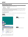
Screenshot 1
The "Panasonic IP Setup" starts up.
The MAC address and the IP address of the connected camera
will be displayed. (Click the “REFRESH” button if they are not
displayed.)
STEP2
Click the MAC address/IP address of the camera to be set up.
STEP3
Click the [NETWORK SETUP] button.
Notes
• When two or more cameras are connected,
the MAC addresses and the IP addresses of
all the connected cameras will be displayed.
• The “Panasonic IP Setup” software can recognize only those cameras in the same subnet.
• The updated MAC addresses and IP
addresses of all the connected cameras that
are in the same subnet will be displayed by
pressing the REFRESH button.
16
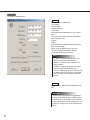
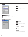
Screenshot 2
The setup window appears.
STEP4
Set parameters for each item.
"IP Address"
"Subnet Mask"
"Default Gateway"
"HTTP Port"
Enter parameters depending on your environment.
For further information about the parameters,
refer to pages 27-28.
"DHCP"
"DNS"
Click the [Enable] radio button when using the
DHCP and the DNS.
When using the DNS function, enter the
“Primary DNS Server address” and the
“Secondary DNS Server address”.
Notes
• If DHCP is enabled although there is no
DHCP server in the network, check
“Disable” for DHCP in the “Panasonic IP
Setup” window.
• If DHCP is enabled, and the DHCP server
has not assigned an IP address yet,
“0.0.0.0” is displayed for the IP address. The
IP address of the camera will be displayed
after the DHCP server assigns one to the
camera.
STEP5
Click the [SET] button after completing the setting.
! Important
It takes around 20 seconds to complete the
settings of the camera after the [SET] button
is pressed. If the AC adapter or the Ethernet
cable is detached before the settings are completed, the settings may not be performed correctly.
17
SETUP
Network Setup of the PC
To set up the network of the PC, first change the TCP/IP settings of the PC to match them to the default settings of
the camera. The following are the default network settings of the camera.
• IP address:
192.168.0.10
• Subnet mask:
255.255.255.0
• Default gateway:
192.168.0.1
To access the camera, the IP address of the PC should be "192.168.0.XXX" (where XXX should be a number from
2 to 254 except 1 and 10). In case the IP address of the camera is set with the "Panasonic IP Setup" software, perform the network setting of the PC according to the network environment.
The settings differ depending on which OS is installed on the PC. Confirm which OS is installed on your PC, and
proceed with the settings corresponding to your OS.
Using Windows 98 SE
The following procedures are examples when using Windows 98 SE. You can proceed in the same way when using
Windows Me.
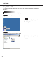
Screenshot 1
Begin the setup when the PC is in the same condition as just
after the startup.
STEP1
Select "Control Panel" ([Start] - [Settings] [Control Panel]).
Screenshot 2
The "Control Panel" window appears.
STEP2
Click once to select the [Network] icon.
18
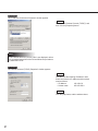
Screenshot 3
The "Network" window appears.
STEP3
Click the [Configuration] tab.
STEP4
Click to select the TCP/IP protocol of the currently used network card.
STEP5
Click the [Properties] button.
Note
If the “TCP/IP” item is not displayed, refer to the operating
instructions of the OS and follow the procedures to install the
TCP/IP.
Screenshot 4
The "TCP/IP Properties" window appears.
STEP6
Click the [IP Address] tab.
STEP7
Click the "Specify an IP address" radio button.
STEP8
Enter the IP address and the subnet mask as
follows.
• IP Address:
192.168.0.9
• Subnet Mask:
255.255.255.0
STEP9
Click the [OK] button, and the window closes.
STEP10
Restart the PC to make the IP address valid.
19
SETUP
Using Windows 2000
The following procedures are examples when using Windows 2000. You can proceed in the same way when using
Windows NT.
! Important
Log in as one of the administrators before beginning the setup.
Screenshot 1
Begin the setup when the PC is in the same condition as just
after the startup.
STEP1
Select "Network and Dial-up Connections"
([Start] - [Settings] - [Network and Dial-up
Connections]).
Screenshot 2
The "Network and Dial-up Connections" window appears.
STEP2
Click the right mouse button on the "Local Area
Connection" icon, and select "Properties" from
the pop-up menu.
20
Screenshot 3
The "Local Area Connection Properties" window appears.
STEP3
Click to select "Internet Protocol (TCP/IP)", and
then click the [Properties] button.
Note
If the “Internet Protocol (TCP/IP)” item is not displayed, refer to
the operating instructions of the OS and follow the procedures
to install the TCP/IP.
Screenshot 4
The "Internet Protocol (TCP/IP) Properties" window appears.
STEP4
Click the "Use the following IP address" radio
button and enter the IP address and the subnet
mask as follows.
• IP address:
192.168.0.9
• Subnet mask:
255.255.255.0
STEP5
Click the [OK] button, and the window closes.
21
SETUP
Using Windows XP (Category View)
Screenshot 1
Begin the setup when the PC is in the same condition as just
after the startup.
STEP1
Select "Control Panel" ([Start] - [Control Panel]).
Screenshot 2
The "Control Panel" window appears.
STEP2
Double click the "Network and Internet
Connections" icon.
Screenshot 3
The "Network and Internet Connections" window appears.
STEP3
Double click the "Network Connections" icon.
22
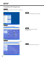
Screenshot 4
The "Network Connections" window appears.
STEP4
Click to select "Local Area Connection", and
then click "Change settings of this connection"
in the "Network Tasks" menu.
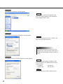
Screenshot 5
The "Local Area Connection Properties" window appears.
STEP5
Click to select "Internet Protocol (TCP/IP)", and
then click the [Properties] button.
Note
If the “Internet Protocol (TCP/IP)” item is not
displayed, refer to the operating instructions of
the OS and follow the procedures to install the
TCP/IP.
Screenshot 6
The "Internet Protocol (TCP/IP) Properties" window appears.
STEP6
Click the "Use the following IP address" radio
button and enter the IP address and the subnet
mask as follows.
• IP address:
192.168.0.9
• Subnet mask:
255.255.255.0
STEP7
Click the [OK] button, and the window closes.
23
SETUP
Network Setup of the Camera
After completing the network setup of the PC, begin the network setup of the camera.
If multiple cameras are connected, it is required to set up each camera individually.
The following information is necessary for the network setup of the cameras.
If you do not have the following information, refer to your network administrator or your Internet service provider.
For further information about the terms, refer to page 69.
• IP address
• Subnet mask
• Port number
• Default gateway (when using a gateway server or a router)
• Primary and secondary DNS server address (when using DNS)
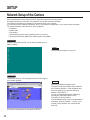
Screenshot 1
Begin the setup when the PC is in the same condition as just
after the startup.
STEP1
Start up Internet Explorer on your PC.
Screenshot 2
The browser starts up. The web page set as the home page in
your browser appears.
STEP2
Enter the IP address assigned by the
“Panasonic IP Setup” software in the “Address”
box of Internet Explorer. (If the IP address has
not been assigned yet, enter the default IP
address “192.168.0.10”.)
You can confirm the assigned IP address by
pressing the “REFRESH” button in the
“Panasonic IP Setup” window.
If the broadband router is set to use the address
translation, enter [IP address + : (colon) + port
number] in the “Address” box, and press the
enter key.
(The picture is the page of the Panasonic web site.)
24
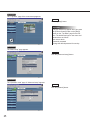
Screenshot 3
The “Top Menu” page of the camera setup appears.
STEP3
Click the [Setup] button.
! Important
The login window will appear when you press
the [Camera Control] button or the [Setup]
button on the “Top Menu” page for the first
time. The default settings for user name and
password are as follows.
User name: admin
Password: password
Change the default password for security.
Screenshot 4
The “Basic setup” page appears.
STEP4
Click the [Advanced setup] button.
Screenshot 5
The “Operation mode” page of “Advanced setup” appears.
STEP5
Click the [Network] button.
25
SETUP
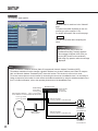
Screenshot 6
The "Network" page appears.
STEP6
Set parameters for each item in the "Network"
page.
The parameters differ depending on the connection type (refer to pages 12-14).
For further information, refer to the next page.
STEP7
Click the [SET] button after completing the
setup.
! Important
After you click the [SET] button, the
“Command Executing” message appears.
(This message will appear even when you
click the [SET] button in other windows.)
Avoid doing any operation while the message
is displayed.
Note
• About the address translation function (Static IP masquerade, Network Address Translation (NAT))
The address translation function changes a global IP address to a private IP address, and “Static IP masquerade” and “Network Address Translation (NAT)” have this function. This function is to be set in a router.
To browse camera pictures via the Internet by connecting the camera to a broadband router, it is necessary to
assign a respective port number for each camera and address translation by using the address translation function. For further information, refer to the operating instructions of the broadband router.
Broadband router
Global address
for the WAN
vvv.xxx.yyy.zzz
Private address
for the LAN
192.168.0.254
Enter [Global IP address + : (colon) + port number]
in the “Address” box of the browser via the Internet.
vvv.xxx.yyy.zzz:82
vvv.xxx.yyy.zzz:81
Address translation
vvv.xxx.yyy.zzz:82 → 192.168.0.2:82
Private address
192.168.0.2
Port number: 82
Internet
(WAN)
Cable modem or
xDSL modem
Address translation
vvv.xxx.yyy.zzz:81 → 192.168.0.1:81
Private address
192.168.0.1
Port number: 81
26
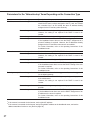
Parameters for the "Network setup" Items Depending on the Connection Type
Item
Connection type
Description of the parameter
IP address
Connection type 1
Enter “xxx.yyy.zzz.nnn” for the IP address (where “xxx.yyy.zzz”
should be the same numbers assigned to the PC, and “nnn” should
be a number from 2 to 254 except the same IP address already
assigned to the PC and any other cameras).
Connection type 2
Set the IP address designated by your network administrator.
However, the setting is not required if the DHCP is used in an
intranet.
Connection type 3*1
Set the IP address designated by your Internet service provider.
Connection type 4*2
If the broadband router uses the DHCP: No setting required
If the broadband router does not use the DHCP: Assignment of a
private IP address is required. However, the IP addresses already
assigned to the PC and other cameras are not available.
For further information, refer to the operating instructions of the
broadband router.
Connection type 1
Use the default setting "255.255.255.0" for the subnet mask.
Connection type 2
Set the subnet mask designated by your network administrator.
However, the setting is not required if the DHCP is used in an
intranet.
Connection type 3
Set the subnet mask designated by your Internet service provider.
Connection type 4
If the broadband router uses the DHCP: No setting required
If the broadband router does not use the DHCP: Setting of the subnet mask is required.
For further information, refer to the operating instructions of the
broadband router.
Connection type 1
If the IP address is set for “xxx.yyy.zzz.nnn”, enter “xxx.yyy.zzz.1”
for the default gateway.
Connection type 2
Set the IP address of the default gateway designated by your network administrator.
However, the setting is not required if the DHCP is used in an
intranet.
Connection type 3
Set the default gateway designated by your Internet service
provider.
Connection type 4
If the broadband router uses the DHCP: No setting required
If the broadband router does not use the DHCP: Assignment of an
IP address to the router is required.
For further information, refer to the operating instructions of the
broadband router.
Netmask
Default gateway
*1
*2
27
If the camera is accessed via the Internet, set the global IP address.
If the camera is accessed via the Internet, assign the global IP address to the broadband router, and set the
address translation function to use. (Refer to page 26.)
SETUP
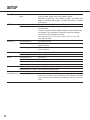
Network speed
Common to all connection
types
HTTP port
Connection type 1, 2 and 3 Use the default setting “80” for the HTTP port.
Host name
BOOTP
DHCP
DNS
Set the network speed.
Use the default setting “auto” for the network speed.
Selectable parameters: auto (default setting), 100 Mbps (full
duplex), 100 Mbps (half duplex), 10 Mbps (full duplex), 10 Mbps
(half duplex)
Connection type 4
If multiple cameras are connected, it is required to set up each camera individually.
However, the port numbers already assigned to other hardware are
not available. The following port numbers are also not available
because this camera already uses them.
Port number: 20, 21, 23, 25, 42, 67, 68, 69, 105, 110, 123, 161,
162, 546, 547, 5002
Connection type 1
No setting required
Connection type 2
Refer to your network administrator and set the designated host
name if required.
Connection type 3 and 4
Refer to your Internet service provider and set the designated host
name if required.
Connection type 1 and 2
Set to ON when using the “Panasonic IP Setup” software.
Connection type 3 and 4
No setting required
Connection type 1
Set to OFF.
Connection type 2
Set to ON if the intranet uses the DHCP.
Connection type 3
Set to OFF.
Connection type 4
Set to ON if the broadband router uses the DHCP.
Connection type 1
Set to OFF.
Connection type 2, 3 and 4 Set to ON when using the DNS.
Primary server
Connection type 1
No setting required
Secondary server Connection type 2, 3 and 4 Set the IP address of the DNS server when using the DNS.
Refer to your Internet service provider for the IP address of the DNS
server. Primary and secondary IP addresses can be set for the
DNS.
28
Installation of the MPEG-4 Plug-in
Installation of the plug-in is required to browse motion pictures.
Insert the provided CD-ROM into the CD-ROM drive of the PC. The launcher software starts up automatically. Click
the [MPEG-4 Installation] button.
After the installer starts up, follow the instructions of the wizard.
! Important
• The MPEG-4 plug-in is exclusively designed for Internet Explorer. This plug-in does not work with other
browsers.
• The MPEG-4 plug-in does not work on a Windows NT computer.
• Login as administrator when installing the MPEG-4 plug-in on a Windows 2000 computer. If your PC has
Windows XP installed, login as the administrator of the PC.
• Set the monitor to True Color (24-bit color) or more.
• If a firewall (including software) exists, allow access to all UDP ports. Otherwise, it is impossible to browse
motion pictures.
Note
I If you need to uninstall the plug-in, follow the steps below.
1. Open the "Control Panel" ([Start] - [Setting] - [Control Panel]).
2. Double click the "Add or Remove Programs" icon.
3. Select "Web Video" and press the [Change / Remove] button.
4. Follow the instructions of the wizard to uninstall the plug-in.
29
SETUP
Basic Settings
After completing the network setup of the PC and the camera, begin the basic settings of the camera.
The basic settings are the minimum settings required to operate the camera, such as date setting and setting of
"Operation mode".
Screenshot 1
Begin the setup when the PC is in the same condition as just
after the startup.
STEP1
Start up Internet Explorer on your PC.
Screenshot 2
The browser starts up. The web page set as the home page in
your browser appears.
STEP2
Enter the IP address assigned by the
“Panasonic IP Setup” software in the “Address”
box of Internet Explorer. (If the IP address has
not been assigned yet, enter the default IP
address “192.168.0.10”.)
You can confirm the assigned IP address by
pressing the “REFRESH” button in the
“Panasonic IP Setup” window.
If the broadband router is set to use the address
translation, enter [IP address + : (colon) + port
number] in the “Address” box, and press the
enter key.
(The picture is the page of the Panasonic web site.)
Refer to page 17 about the IP address setting.
30
Screenshot 3
The "Top Menu" page appears.
STEP3
Click the [Setup] button.
! Important
The login window will appear when you press
the [Camera Control] button or the [Setup]
button on the “Top Menu” page for the first
time. The default settings for user name and
password are as follows.
User name: admin
Password: password
Change the default password for security.
Screenshot 4
The "Basic setup" page appears.
STEP4
! Important
The time on the browser will be displayed as hours
and minutes (00:00), though you can set hours, minutes and seconds in "Time setup".
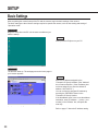
Set up the items on the "Basic setup" page.
This explanation is only for "Camera setup".
"Camera name"
Enter a name for the camera. The entered camera name will be displayed when the reload button of the browser is pressed or when the
browser starts up the next time.
Characters for "Camera name": Up to 32 characters
"Time setup (year-month-day hour:min:sec)"
Set the date and the time.
Year:
Enter 4 digits.
Month and day: Enter 2 digits each.
Hour, minute and second:
Enter 2 digits each, and
divide by colon (:).
"Power/Link/Access LED"
Click the "ON" radio button to use the LED as
status display.
Click the "OFF" radio button to turn off the LED
all the time.
"Camera position"
Select "Desk top" or "Wall mount" according to
where the camera is installed.
STEP5
Click the [SET] button after completing the setting.
31
BROWSING PICTURES
If the setup has been completed, you can browse through the pictures on the camera.
The pictures of the camera can be displayed as still pictures or motion pictures.
Displaying multiple pictures of multiple cameras on a screen is also possible.
To display multiple pictures of multiple cameras on a screen, refer to page 36.
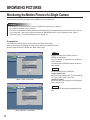
Monitoring a Still Picture of a Single Camera
Set as follows to monitor a still picture (JPEG) of a single camera.
Preparations
The setting for still pictures can be made in the "Basic setup" page.
Start up the browser and display the "Basic setup" page of the desired camera.
Refer to page 24 and 25 to display the "Basic setup" page.
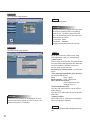
STEP1
Click the "JPEG" radio button for "Operation
mode selection".
STEP2
Begin the settings for JPEG.
"JPEG mode setup"
Set the following items for JPEG.
"Refresh interval"
Select a refresh interval from the following.
Fast / Middle / Slow / Very Slow
"Image capture size"
Select an image capture size from the following.
VGA (640 x 480) / QVGA (320 x 240) / QQVGA
(160 x 120)
"Quality of image"
Select a quality of the image from the following.
Super Fine / Fine / Normal / Low
STEP3
Click the [SET] button after completing the settings.
32
How to operate
If the preparations have been completed, you can begin the operation from the "Basic setup" page.
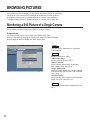
Screenshot 1
Begin the operation from the "Basic setup" page.
STEP1
Click the "Control" button.
STEP2
Screenshot 2
The "Control" page appears and the still picture of the camera is displayed. Operation buttons are displayed below the
still picture.
Note
• If the preparations have been completed, start up the
browser and display the "Top Menu" page of the desired
camera. The camera picture appears on the "Top Menu"
page.
• Several pictures shot during the panning/tilting may not
be displayed when “Refresh interval” is set to “Very
Slow”.
33
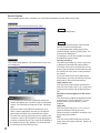
Operate the camera and adjust the picture.
Panning and tilting
Click the arrow buttons (up / down / right / left)
to adjust the horizontal and vertical position.
The center of the box surrounded by the arrow
buttons (the point where the horizontal line and
the vertical line cross) is the current position of
the camera.
If you click inside the box surrounded by the
arrow buttons, you can pan and tilt the camera
wider than by clicking the arrow buttons.
Image capture size
Click one of the picture resolution buttons (VGA
(640 x 480) / QVGA (320 x 240) / QQVGA (160
x 120)) to display the picture with the desired
resolution.
Adjustment of the brightness of the picture
Click the buttons to adjust the brightness of the
picture. The left end button (-) is the darkest and
the right end button (+) is the brightest.
Image Size
Click one of the buttons (x1.0 / x1.5 / x2.0) to
select the desired image size.
When the picture is magnified, the quality of the
picture may be decreased.
AUX
Click one of the buttons (High/Low) to set the
status of the AUX output connector. (Refer to p.
53 for details.)
One time pan
You can monitor the picture by panning the
camera one time to the left and right.
BROWSING PICTURES
Monitoring the Motion Picture of a Single Camera
Set as follows to monitor the motion picture (MPEG-4) of a single camera.
! Important
• To monitor the motion picture of a camera, installation of the plug-in is required.
For further information, refer to page 29.
• You may have problems browsing motion pictures depending on the bandwidth of the network to which the camera is connected. In this case, perform the setting of “Bandwidth control” on the “Operation mode” page of
“Advanced setup”. For further information, refer to page 55.
Preparations
The setting for motion pictures can be made in the "Basic setup" page.
Start up the browser and display the "Basic setup" page of the desired camera.
Refer to page 24 and 25 to display the "Basic setup" page.
STEP1
Begin the setting of the motion picture in
"MPEG-4 mode setup".
Click the "MPEG-4" radio button for "Operation
mode selection".
The parameters for MPEG-4 setting automatically appear.
STEP2
(When “JPEG” is selected)
Set the following items for MPEG-4.
"Image capture size"
Select an image capture size from the following.
CIF (352 x 288) / QCIF (176 x 144)
"Quality of image"
Select a quality of the image from the following.
Fine / Normal / Low
STEP3
Click the [SET] button after completing the setting.
(When “MPEG-4” is selected)
34
How to Operate
If the preparations have been completed, you can begin the operation from the "Basic setup" page.
Screenshot 1
Begin the operation from the "Basic setup" page.
STEP1
Click the [Control] button.
STEP2
Screenshot 2
The "Control" page appears. The motion picture of the camera is displayed.
Notes
• If the preparations have been completed, start up the
browser and display the “Top Menu” page of the desired
camera. The camera picture appears on the “Top Menu”
page.
• The port number for the MPEG-4 streaming is set to
5004. If another application uses this port, change the
port number to another even-numbered port number.
• To switch the currently monitored picture to another camera picture, click the [STOP] button to stop displaying the
currently monitored picture. Then, enter the IP address of
the desired camera in the “Address” box of the browser
to monitor the desired camera picture.
35
To display the motion picture of the selected
camera, click the [Live-ON] button.
To quit displaying the motion picture of the
selected camera, click the [STOP] button. The
motion picture disappears.
On this page, you can also operate the camera
and adjust the motion picture.
Panning and tilting
Click the arrow buttons (up / down / right / left)
to adjust the horizontal and vertical position.
The center of the box surrounded by the arrow
buttons (the point where the horizontal line and
the vertical line cross) is the current position of
the camera.
If you click inside the box surrounded by the
arrow buttons, you can pan and tilt the camera
wider than by clicking the arrow buttons.
Image capture size
Click one of the motion picture resolution buttons (CIF (352 x 288) / QCIF (176 x 144)) to display the motion picture with the desired resolution.
Adjustment of the brightness of the motion
picture
Click the buttons to adjust the brightness of the
motion picture. The left end button (–) is the
darkest and the right end button (+) is the
brightest.
Image Size
Click one of the buttons (x1.0 / x1.5 / x2.0) to
select the desired motion picture size.
When the picture is magnified, the quality of the
picture may be decreased.
AUX
Click one of the buttons (High/Low) to set the
status of the AUX output connector. (Refer to p.
53 for details.)
BROWSING PICTURES
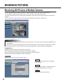
Monitoring Still Pictures of Multiple Cameras
You can monitor pictures of multiple cameras on a single monitor screen (multi-screen) simultaneously.
You can display multiple camera pictures from up to four cameras on a single monitor screen.
To monitor camera pictures on the multi-screen, registration of the cameras to be monitored on the multi-screen is
required.
You can register up to eight cameras as two groups by registering four cameras in each group.
! Important
• Only still pictures (JPEG) can be monitored on a multi-screen. You cannot monitor motion pictures (MPEG-4) on
a multi-screen.
• Select “OFF” for both “Host authentication” and “User authentication” of the camera to be registered for monitoring on the multi-screen, or set the same user name and password to all of the cameras to be registered.
Preparations
Register the cameras to be monitored on the multi-screen.
First, the setting for still pictures on the "Basic setup" page is required.
Start up the browser and display the "Basic setup" page of the desired camera.
Refer to page 24 and 25 to display the "Basic setup" page.
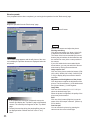
Screenshot 1
Begin the operation from the "Basic setup" page.
STEP1
Click the "JPEG" radio button for "Operation
mode selection".
STEP2
Set the details for JPEG in "JPEG mode setup".
For further information, refer to page 32.
STEP3
Click the [Advanced setup] button.
36
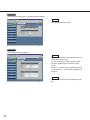
Screenshot 2
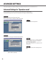
The "Operation mode" page of "Advanced setup" appears.
STEP4
Click the [Multi-screen] button.
Screenshot 3
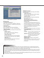
The "Multi-screen" page appears.
STEP5
Set the IP addresses of the cameras to be monitored on the multi-screen.
You can register up to eight cameras as two
groups by registering four cameras in each
group.
Camera 1 – Camera 4 are registered as Group
A, and Camera 5 – Camera 8 are registered as
Group B.
STEP6
Click the [SET] button after completing the setting.
37
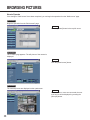
BROWSING PICTURES
How to Operate
If the settings of “Multi-screen” have been completed, you can begin the operation from the “Multi-screen” page.
Screenshot 1
Begin the operation from the "Multi-screen" page.
STEP1
Click the [Control] button in the top left corner.
Screenshot 2
The "Control" page appears. The still picture of the camera is
displayed.
STEP2
Click the [Quad screen] button.
Screenshot 3
The camera pictures are displayed on the quad screen.
STEP3
If five cameras or more are connected, the next
multi-screen will be displayed by pressing the
[Group B] button.
38
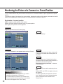
Monitoring the Picture of a Camera in a Preset Position
You can monitor both the still picture and the motion picture of a camera installed in a place registered as a preset
position.
To monitor the image of the camera in a preset position, adjusting the position of the camera (horizontal and vertical
position) and registering the shooting location, as a preset position is required in advance.
Registration of a preset position
Begin to register a preset position of the camera.
Register the preset number and preset name of a preset position.
Up to eight preset positions can be registered.
Screenshot 1
Begin the operation from the "Control" page.
STEP1
Click "Preset Setup".
Screenshot 2
The "Preset registration" area appears below the list of "Preset".
STEP2
Click the arrow buttons (up / down / right / left)
to adjust the horizontal and vertical position of
the picture.
STEP3
After the adjustment of the position has been
completed, select a preset number and enter a
preset name for the preset position.
Characters for the preset name: 1 character
to 32 characters
STEP4
! Important
• If the preset position is not registered, you cannot
add the preset position to "Preset tour".
• If a preset name is not entered, you cannot select
the preset position. (Preset name cannot be clicked
as it does not appear in the “Preset” area.)
39
Click the [SET] button after completing the setting.
Repeat STEP 2 to STEP 4 to register more preset positions.
To add a registered preset position to "Preset
tour", check the box next to the desired preset
name. (Uncheck the box to delete it from
"Preset tour".)
BROWSING PICTURES
How to Operate
Monitor the picture of the camera in a preset position.
First, select whether a still picture or a motion picture is to be monitored in a preset position on the "Basic setup"
page. Refer to page 24 and 25 to display the "Basic setup" page.
Screenshot 1
Begin the operation from the "Basic setup" page.
STEP1
Select whether a still picture or a motion picture
is to be monitored in a preset position.
Refer to page 32 to monitor a still picture, and
page 34 to monitor a motion picture.
STEP2
After the setting has been completed, click the
[Control] button.
Screenshot 2
The "Control" page appears.
(This screenshot is displayed when you choose a still picture to
be monitored in a preset position.)
STEP3
Click the desired preset name from the list of
"Preset".
Screenshot 3
The picture of the camera in the selected preset position
appears.
Notes
• You can also operate the camera and adjust
the picture. For further information, refer to
page 33.
• To register more preset positions or change
a registered preset position, click "Preset
Setup". The "Preset registration" area
appears below the list of "Preset" and you
can register or change preset positions.
40
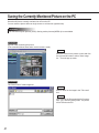
Saving the Currently Monitored Picture on the PC
Save the still picture currently monitored as a file on the PC.
You can save the picture either as single screen or multi-screen (quad screen).
! Important
You can save only still pictures (JPEG). Saving motion pictures (MPEG-4) is not available.
Screenshot 1
Operate while monitoring the picture.
(The screenshot below shows when a multi-screen is used.)
STEP1
Move the cursor on the picture to save and click
the right mouse button to select "Save Image
As..." from the pop-up menu.
Screenshot 2
The "Save Picture" window appears.
STEP2
Enter a name for the image in the "File name"
box.
STEP3
After entering the file name with the file extension “.jpg”, click the [Save] button. The picture
will be saved on the PC.
41
DETECTING MOTION IN THE MONITORED AREA
When motion is detected in the monitored area, "Alarm" appears on the monitor screen. Simultaneously, you can
save the picture of the alarmed area and send an alarm mail by e-mail (motion detector function).
You can also automatically transfer the saved image to the server.
To activate these functions, complete the setting of the "Alarm" page or the "FTP client" page in advance.
Notes
• In case a sensor is connected to the alarm connector of the camera, the functions above are available when the
sensor detects motion.
• To reset an alarm, click "Alarm" on the monitor screen.
Motion Detector Function
By using the motion detector function, the alarm signal is sent when motion (changes in the brightness level) is
detected in the designated area. With this camera, you can save the picture of the designated area or send an
alarm mail when motion is detected.
Set the detection area and the other conditions required for the motion detector function on the "VMD area" page.
! Important
The motion detector function is available only when "JPEG" is selected for the "Operation mode selection" on the
"Operating mode" page of "Advanced setup". When the motion detector function is activated, the speed of loading
still pictures (JPEG) may become slower. The motion detector function does not work when "MPEG-4" is selected.
Action when Motion is Detected
By setting the motion detector function, you can set the camera to activate the following operations when motion
(changes in the brightness level) is detected in the designated area.
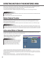
• When motion is detected, "Alarm" appears on the
monitor screen as shown in screenshot below.
"Alarm" will disappear by clicking on it.
Note
The camera checks the alarm status and reloads the
browser page by the minute or when the reload button is pressed. Therefore, approximately a minute
delay at the maximum may occur until "Alarm"
appears on the browser after an alarm occurred.
• You can save the picture of the area where motion is detected on the camera.
Number of pictures you can save: 30 pictures max. per 1 alarm (You can set the number of images to be saved up
to 20 pictures for pre-alarm and up to 20 pictures for post-alarm, but the total number of images to be saved should
be 30 pictures max.)
Maximum number of pictures saved:
Up to 60 pictures without reference to sizes.
The older pictures will automatically be deleted if the number of the pictures exceeds 60 pictures.
42
• Inform by sending e-mails.
You can send an alarm mail that notifies an alarm has occurred and the alarm date and time to a designated e-mail
address registered in advance.
You can also attach a picture to that mail.
You can register up to four e-mail addresses to which this alarm mail will be sent.
Contents of the alarm mail:
“In WV-NM100, Alarm was occurred.
Date: XXXX.XX.XX.XX:XX:XX
URL: http:// xxx.yyy.zzz.nnn/alarm/image/*****.jpg”
(XXXX.XX.XX.XX:XX:XX is the date: year-month-day hour:min:sec)
(xxx.yyy.zzz.nnn is the IP address of the camera)
(***** is the file name)
The alarm mail contains the link address to the saved picture on the camera. This link address is available only
when a global IP address is assigned to the camera. If a private address is assigned to the camera, only PCs in the
same subnet of the camera can access to this link address. However, the picture accessed from the link address
may have been deleted if alarms occur frequently.
You can customize the contents of the alarm mail. For further information, refer to page 53.
Note
When user authentication is activated on the “User authentication” page, authentication is required before users
access the picture. (Refer to p.60.)
• Transfer the saved pictures to the server.
You can transfer the pictures saved in the camera to a server designated in advance. Refer to page 49 for the settings.
Settings of the Actions to be Performed when Motion is Detected
Set actions to be performed when motion is detected.
The settings can be made in the "Alarm" page.
Screenshot 1
Begin the operation from the "Basic setup" page.
Refer to page 24 and 25 to display the "Basic setup" page.
STEP1
Click the [Advanced setup] button.
43
DETECTING MOTION IN THE MONITORED AREA
Screenshot 2
The "Operation mode" page of "Advanced setup"
appears.
STEP2
Click the [Alarm&Transmission] button.
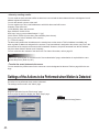
Screenshot 3
The "Alarm" page appears.
STEP3
Set the items on the "Alarm" page.
Refer to the next page for details about each
item.
STEP4
Click the [SET] button after completing the setting.
44
Items on the "Alarm" page
[E-mail notice setup]
"E-mail notice"
Select "ON" or "OFF" to set whether to notice by e-mail
or not when an alarm occurs.
"SMTP server address"
Enter the SMTP server address of the sender
"Authentication"
Select "SMTP", "POP3" or "None" for the authentication.
"SMTP": Authentication by the SMTP server
"POP3": Authentication by POP before SMTP
"None": No authentication
"POP3 server address"
Enter the POP3 server address when "POP3" is
selected for "Authentication".
"User name"
Enter the name of the sender, up to 64 characters.
"Password"
Enter a password of the sender mail address, up to 64
characters.
"Sender mail address"
Enter the sender mail address.
"Attach image"
Select "ON" or "OFF" to set whether to attach an
image or not when sending an e-mail. (Only still picture
can be attached.)
"Destination E-mail address"
Enter the e-mail address of the recipient. Up to four
recipients can be registered.
"Delete destination E-mail address"
Click the [o] button to check the registered e-mail
address of the recipient.
You can delete the selected e-mail address of the
recipient by clicking the [DEL] button.
[Alarm setup]
"External alarm input"
Select "ON" or "OFF" to set whether to receive alarm
input signals or not. For further information, refer to
page 53.
[Alarm common setup]
"Pre-alarm"
"Number of image": Set the number of images to
store in pre-alarm. You can select a number
between 0 and 20.
"Post-alarm"
"Number of image": Set the number of images to
store in post-alarm. You can select a number
between 0 and 20.
45
"Interval": Select a frame rate for the image to
store among the following:
1/10, 1/5, 1/3, 1/2, 1, 2, 3, 5, 10 (sec)
[External alarm output]
"Alarm type"
Select "Latch" or "Pulse" for the alarm output mode.
"Pulse width"
Set the pulse width for the alarm output.
"Latch reset"
When resetting of the alarm output latching is required,
click the [Reset] button.
[Video Motion Detection (VMD)]
"VMD"
Select "ON" or "OFF" to activate the motion detector
function.
"VMD sensitivity"
Select a sensitivity level for the motion detector among
the following:
High / Middle / Low
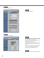
[Panasonic Protocol]
This function is not available yet, however it will be
supported in future.
“Panasonic Protocol”
Currently not available. Do not change the default setting (OFF).
“Destination port”
Currently not available. Do not change the default setting.
“Retry number of times”
Currently not available. Do not change the default setting.
“Destination IP address”
Currently not available. Do not change the default setting.
“Delete destination IP address”
Currently not available. Do not change the default setting.
! Important
• Up to 60 pictures can be saved. The older pictures
will automatically be deleted if the number of the
pictures exceeds 60 pictures.
• If “1/10” or “1/5” is selected for “Interval” of “Postalarm”, the interval to store the image may be
longer than the setting.
DETECTING MOTION IN THE MONITORED AREA
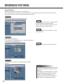
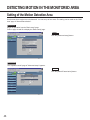
Setting of the Motion Detection Area
Set the area where motion has to be detected. You can set up to four areas. The setting can be made on the "VMD
area" page of "Alarm&Transmission".
Screenshot 1
Begin the operation from the "Basic setup" page.
Refer to page 24 and 25 to display the "Basic setup" page.
STEP1
Click the [Advanced setup] button.
Screenshot 2
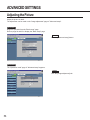
The "Operation mode" page of "Advanced setup" appears.
STEP2
Click the [Alarm&Transmission] button.
46
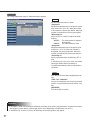
Screenshot 3
The "Alarm" page appears.
STEP3
Click the [VMD area] tab.
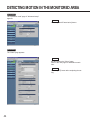
Screenshot 4
The "VMD area" page appears.
STEP4
Select the desired area number to be registered
by clicking the [Area 1] - [Area 4] radio buttons.
Up to four areas can be designated.
Designate the area for the selected area number by clicking on the picture.
To designate the area, click the top left corner
and the bottom right corner of the area you wish
to set.
To cancel the designated area, select the area
number to be canceled from the pull-down
menu, and press the [RESET] button.
STEP5
Click the [SET] button after completing the setting.
47
DETECTING MOTION IN THE MONITORED AREA
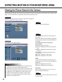
Viewing the Picture Stored in the Camera
Check the picture stored in the camera when the alarm occurred. This operation can be made on the "Alarm log list"
page. You can browse the saved pictures after the alarm has been reset.
Screenshot 1
Begin the operation from the "Top Menu" page. Refer to page 24
and 25 to display the "Top Menu" page.
STEP1
Click the [Alarm log list] button.
STEP2
Screenshot 2
The "Alarm log list" page appears.
! Important
• Though the "Alarm log list" displays up to 100 alarm logs,
only 60 pictures can be stored at the maximum.
• Depending on the traffic of the network, a drop frame may
occur while monitoring alarm pictures. If this occurs, click
the [B] button or the [A] button to monitor each frame.
• Display the saved still pictures (JPEG) using the web
browser. Some image-editing software cannot open or
display the saved still pictures.
48
Click the desired log from the alarm log list on
the left side.
The picture (JPEG) of the selected log appears
on the right side. (Only if the selected picture is
remaining.)
To view the previous or next picture
automatically
Operate the “Control” buttons.
[B] button: Displays the next picture automatically.
[A] button: Displays the previous picture automatically.
[y] button: Stops displaying the picture automatically.
[d] button: Displays the last picture.
[s] button: Displays the first picture.
JPEG
n (current frame number)/nn (total frame number) appears in the box surrounded by [B] and
[A] buttons.
[B] button: Displays the next frame.
[A] button: Displays the previous frame.
Image Size
Click one of the buttons (x1.0 / x1.5 / x2.0) to
select the desired image size.
STEP3
To return to the current camera picture, click the
"Control" button.
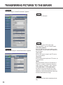
TRANSFERRING PICTURES TO THE SERVER
Transfer the pictures stored in the camera to the server. The transfer to the server can be made in the two following
ways:
• Transfer pictures when an alarm occurred in the motion detection area.
• Transfer pictures at designated intervals.
To transfer the pictures to the server, the settings are required in advance.
! Important
Only still pictures can be transferred to the server. Transferring motion picture to the server is not possible.
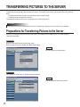
Preparations for Transferring Pictures to the Server
Set the FTP settings to transfer pictures to the server. The settings can be made on the "FTP client" page of
"Alarm&Transmission".
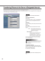
Screenshot 1
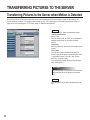
Begin the operation from the "Basic setup" page.
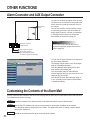
Refer to page 24 and 25 to display the "Basic setup" page.
STEP1
Click the [Advanced setup] button.
Screenshot 2
The "Operation mode" page of "Advanced setup" appears.
STEP2
Click the [Alarm&Transmission] button.
49
TRANSFERRING PICTURES TO THE SERVER
Screenshot 3
The "Alarm" page of "Alarm&Transmission" appears.
STEP3
Click the [FTP client] tab.
STEP4
Screenshot 4
The "FTP client" page of "Alarm&Transmission" appears.
Set the items on the "FTP client" page.
This explanation is only for "Common setup".
"FTP server address"
Enter the address of the server where to transfer the picture. You can enter the IP address or
the host name.
"User name"
Enter a user name for login in the FTP server,
up to 64 characters.
"Password"
Enter a password for login in the FTP server, up
to 64 characters.
"Mode"
Select the transfer mode from "Sequential" or
"Passive". In case the connection can not be
made selecting "Sequential", select "Passive".
"FTP enable time 1" "FTP enable time 2"
Set the day of the week and the time range
(start time – finish time) for the pictures to be
transferred. Check the desired day of the week
and enter the desired time range.
STEP5
Click the [SET] button after completing the setting.
50
Transferring Pictures to the Server at Designated Intervals
Set the interval time to transfer pictures to the server at designated intervals.
The setting can be made on the "FTP client" page of "Alarm&Transmission". Refer to page 49 and 50 to display the
"FTP client" page of "Alarm&Transmission".
STEP1
Set the items for "Non alarm transmission
setup".
"Non alarm transmission"
Check "ON".
You can select "ON" or "OFF" to set whether to
transfer the picture at designated intervals or
not.
"Directory"
Enter the directory where the pictures should be
stored.
"File name"
Enter the file name of the picture to be transferred.
"Fix": The file name of the picture to
be transferred is the name designated in "File name".
"Date & Time":
The file name of the picture to be
transferred will be "File name +
sequential number + month / day /
hours / minutes / seconds / year".
The sequential number will be given starting
from 1 automatically.
! Important
The total number of characters of the directory
name and the file name should not exceed
255 characters.
"Transmission interval"
In case "ON" is selected for "Non alarm transmission", enter a number within the range below
for the transmission interval.
0.2 second to 1,440 minutes
STEP2
Click the [SET] button after completing the setting.
51
TRANSFERRING PICTURES TO THE SERVER
Transferring Pictures to the Server when Motion is Detected
Set for the pictures of the motion detection area to be transferred to the server when motion is detected by the
motion detector function. The settings can be made on the "FTP client" page of "Alarm&Transmission". Refer to
page 49 and 50 to display the "FTP client" page of "Alarm&Transmission".
STEP1
Set the items for "Alarm transmission setup".
"Alarm transmission"
Check "ON".
You can select "ON" or "OFF" to set whether to
transfer the pictures or not when an alarm
occurs.
"Directory"
Enter the directory where the pictures should be
stored.
"File name"
The file name to be transferred will be [File
name (name of the picture entered by the user)
+ sequential number + month / day / hours /
minutes / seconds / year].
The sequential number will be given automatically starting from 1.
! Important
The total number of characters of the directory
name and the file name should not exceed
255.
STEP2
Click the [SET] button after completing the setting.
52
OTHER FUNCTIONS
Alarm Connector and AUX Output Connector
Alarm input
Security door
sensor
You can set the alarm operation when an external device such as a sensor is connected to the
alarm connector inside the connector cover of
the camera.
You can set functions such as sending e-mails
or transferring pictures to the server when an
alarm signal is input by a sensor, as explained
in "Settings of the Actions to be Performed
when Motion is Detected" on page 43.
! Important
Alarm input connector
Ground terminal
Do not connect an external device if it is
beyond the specified ratings of the camera
(refer to page 68).
Alarm output connector
AUX output connector
(To control external devices:
for example, lighting ON and OFF)
You can set the type of the device connected to
the AUX output connector.
The settings can be made on the "AUX output"
page of "Alarm&Transmission".
Click the [Alarm&Transmission] button, and
then click the [AUX output] tab.
The "AUX output" page of "Alarm&Transmission" appears and you can check the current
setting of the "AUX setup".
Click the [SET] button after selecting "High" or
"Low", according to the sensor's specifications,
to enable the setting.
Customizing the Contents of the Alarm Mail
You can customize the contents of the alarm mail notifying that an alarm has occurred and the alarm date and time.
To customize them, do the following:
53
STEP1
Create the contents of the alarm mail with a text editor and save the file as "almmail.tmpl".
STEP2
Start up the FTP software and connect to the camera by entering the IP address of the camera.
The destination where to transfer the file is "/flash". The default user name is "admin", and the default
password is "password".
STEP3
Upload the new file (almmail.tmpl) in text format to the camera.
ADVANCED SETTINGS
This section explains the advanced settings for the quality of the pictures, the user authentication, etc.
Advanced Settings for "Operation mode"
Set the "Operation mode" (JPEG / MPEG-4) in more detail than in the "Basic setup".
The advanced setting can be made on the "Operation mode" page of "Advanced setup".
Screenshot 1
Begin the operation from the "Basic setup" page.
Refer to page 24 and 25 to display the "Basic setup" page.
STEP1
Click the [Advanced setup] button.
Screenshot 2
The "Operation mode" page of "Advanced setup" appears.
STEP2
Set the “Advanced setup” for JPEG and MPEG4. (When MPEG-4 is selected, the window in
the following page appears.)
Refer to the next page for the explanation of the
setting items.
STEP3
Click the [SET] button after completing the setting.
(When “JPEG” is selected)
54
(When “MPEG-4” is selected)
Setting items
"Operation mode selection"
Select "JPEG" (still picture) or "MPEG-4" (motion picture). The parameters for J-PEG/MPEG-4 setting automatically appear.
"Bandwidth control"
Select a bandwidth control from the following:
32 / 64 / 128 / 256 / 512 / 1024 / Unlimited (K bps)
"JPEG mode setup"
If "JPEG" is selected, the setting of the following items
is required.
"Refresh interval"
Select a refresh interval from the following:
Fast / Middle / Slow / Very Slow
"Image capture size"
Select an image capture size from the following:
VGA (640 x 480) / QVGA (320 x 240) / QQVGA
(160 x 120)
"Quality of image"
Select a quality of the image from the following.
Super Fine / Fine / Normal / Low
"MPEG-4 mode setup"
If "MPEG-4" is selected, the setting of the following
items is required.
"Image capture size"
Select an image capture size from the following:
CIF (352 x 288) / QCIF (176 x 144)
"Quality of image"
Select a quality of the image from the following.
Fine / Normal / Low
"Max bitrate (per 1 client)"
Select an M-PEG bit rate for each client.
32/64/128/256/512/1024/Unlimited (K bps)
"Refresh cycle"
In a network environment with frequent errors, by
setting the refresh cycle shorter, you can decrease
the cause of interference on the monitor screen.
However, the loading speed may become slower.
Enter a number between 1 and 30 (sec).
"UDP port"
Enter the transmission port number of the camera.
"Transmission type"
Select "Unicast" or "Multicast" for the transmission
setting.
"Unicast": Up to four users can connect to a single camera to monitor the picture.
"Multicast": Maximum number of users connected
in a subnet can connect to a single
camera to monitor the picture.
"Multicast address"
Set the multicast IP address for transmission.
"Multicast port"
Set the multicast port number (number of the port
that the camera uses to transmit the picture) for
transmission.
! Important
• If the setting item is overlapped between "Basic setup" and "Advanced setup", the latest setting has priority.
For example, if a different setting is made on the "Operation mode" page after the same item has been set on
the "Basic setup" page, the setting made on the "Operation mode" page is valid.
• You may have problems browsing still/motion pictures depending on the bandwidth of the network to which the
camera is connected. In this case, perform the setting of “Bandwidth control” on the “Operation mode” page of
“Advanced setup”.
• Depending on the traffic of the network, there might be difficulties displaying the picture. In this case, select Slow
or Very Slow for “Refresh interval” of “JPEG mode setup”.
55
ADVANCED SETTINGS
Adjusting the Picture
Adjust the picture in detail.
The adjustment can be made on the "Image adjustment" page of "Advanced setup".
Screenshot 1
Begin the operation from the "Basic setup" page.
Refer to page 24 and 25 to display the "Basic setup" page.
STEP1
Click the [Advanced setup] button.
Screenshot 2
The "Operation mode" page of "Advanced setup" appears.
STEP2
Click the [Image adjustment] tab.
56
Screenshot 3
The "Image adjustment" page of "Advanced setup" appears.
STEP3
Set and adjust the picture in detail.
"Brightness"
Adjust the brightness level of the picture (seventeen levels from "-8" to "8"). When the number
is decreased, the picture gets darker. When the
number is increased, the picture gets brighter.
"White balance"
Select "AUTO" or "HOLD" to adjust the white
balance.
"AUTO":
The white balance is adjusted
automatically.
"HOLD":
The white balance is fixed.
"Sharpness"
Adjust the sharpness level of the picture (nine
levels from "-4" to "4"). When the number is
decreased, the picture gets softer. When the
number is increased, the picture gets sharper.
"Sensitivity up"
Select a parameter from the following: OFF, 2
to10
If "Sensitivity up" is set to 2 or more, the shutter
speed gets slower and the sensitivity is
increased automatically under low illumination
conditions.
STEP4
Click the [SET] button after completing the setting.
"PAN / TILT calibration"
Correct the misalignment of the lens (horizontal
position / vertical position) with the refresh function.
[REFRESH]
Click this button to refresh.
! Important
• If the object is under low illumination conditions, the quality of the picture may decrease if compared to that with
enough light. (A noisy picture, white-tinged picture, or the appearance of bright spots may occur.)
• If “Sensitivity Up” is set to 2 or more, an afterimage of the moving object may appear.
57
ADVANCED SETTINGS
Settings for the Host Authentication
Begin the setting for the host authentication.
You can set a double authentication for the operation of the camera.
One is the host authentication and the other is the user authentication.
The host authentication checks if an IP address of a PC accessing the camera is registered as a host or not.
Up to eight PCs can be registered for the host authentication.
The setting of the host authentication is made on the "Host authentication" page.
Screenshot 1
Begin the operation from the "Basic setup" page.
Refer to page 24 and 25 to display the "Basic setup" page.
STEP1
Click the [Advanced setup] button.
Screenshot 2
The "Operation mode" page of "Advanced setup" appears.
STEP2
Click the [Authentication] button.
58
Screenshot 3
The "Host authentication" page appears.
STEP3
Begin the setting for the host authentication.
"Host authentication"
Select "ON" or "OFF" to set whether to authenticate hosts or not.
"Host address"
Enter the IP address of the PC to be authenticated.
"Access level"
Select an access level from the following:
Administrator / Camera control / Live viewing
"Administrator": Authorized to operate all
functions of the camera
"Camera control": Authorized to monitor
the picture and operate on the "Alarm log
list" page and the "Camera control"
page. Not authorized to operate on the
"Basic setup" page and the "Advanced
setup" page.
"Live viewing": Authorized only to monitor
the picture. Not authorized to operate the
camera.
STEP4
Click the [SET] button after completing the setting.
Click the "Delete Host" [o] button to check the
IP address of the PCs registered in the host
authentication. You can delete the selected host
by clicking the [DEL] button below. Access
level, which is surrounded by “[ ]”, will appear
beside the host name registered.
Example: 192.168.0.20 [1]
59
ADVANCED SETTINGS
Settings for the User Authentication
Begin the setting for the user authentication.
You can set a double authentication for the operation of the camera.
One is the host authentication and the other is the user authentication.
The user authentication requires users to enter a user name and a password to access the camera if a PC accessing the camera is not registered for the host authentication.
Up to sixteen users can be registered for the user authentication.
The setting of the user authentication is made on the "User authentication" page.
Screenshot 1
Begin the operation from the "Basic setup" page.
Refer to page 24 and 25 to display the "Basic setup" page.
STEP1
Click the [Advanced setup] button.
Screenshot 2
The "Operation mode" page of "Advanced setup" appears.
STEP2
Click the [Authentication] button.
60
Screenshot 3
The [Host authentication] tab appears.
STEP3
Click the [User authentication] tab.
STEP4
Screenshot 4
The "User authentication" page appears.
Begin the setting for the user authentication.
"User authentication"
Select "ON" or "OFF" to set whether to authenticate users or not.
"User name"
Enter a user name of up to 32 characters.
"Password" / "Retype Password"
Enter a password for the user of at least 8 and
no more than 32 characters.
"Access level"
Select an access level from the following:
Administrator / Camera control / Live viewing
"Administrator": Authorized to operate all
functions of the camera
"Camera control": Authorized to monitor
the picture and operate on the "Alarm log
list" page and the "Camera control"
page. Not authorized to operate on the
"Basic setup" page and the "Advanced
setup" page.
"Live viewing": Authorized only to monitor
the picture. Not authorized to operate the
camera.
STEP5
Click the [SET] button after completing the setting.
Click the "Delete User" [o] button to check the
users registered in the user authentication. You
can delete the selected user by clicking the
[DEL] button below. Access level, which is surrounded by “[ ]”, will appear beside the user
name registered.
Example: admin [1]
61
ADVANCED SETTINGS
System Settings
Begin the setting for the system such as date setting, naming the cameras, etc.
The setting is made on the "System" page.
Screenshot 1
Begin the operation from the "Basic setup" page.
Refer to page 24 and 25 to display the "Basic setup" page.
STEP1
Click the [Advanced setup] button.
Screenshot 2
The "Operation mode" page of "Advanced setup" appears.
STEP2
Click the [System] button.
62
Screenshot 3
The "System" page appears.
STEP3
Set the items on the "System" page.
For details about the items, refer below.
STEP4
Click the [SET] button after completing the setting.
Setting items
System
"Time adjustment"
Select a standard for the time adjustment.
Manual setup: Adjust the time manually.
Synchronization with NTP server: Time is adjusted automatically based on the NTP server.
"Time setup (year-month-day hour:min:sec)"
Enter year, month, date, hour, minute, and second if
"Manual setup" is selected for "Time adjustment".
Year: Enter 4 digits.
Month and day: Enter 2 digits each.
Hour, minute and second: Enter 2 digits each, and
divide by colon (:).
"NTP server address"
Enter the address of the NTP server if
"Synchronization with NTP server" is selected for
"Time adjustment".
"NTP port"
Enter the port number of the NTP server.
"Synchronization interval"
Enter “1” to “24” hours for the interval time to access
to the NTP server for synchronization.
"Time zone"
If using the NTP server, select the time zone according to the location where the camera is installed.
63
"Daylight saving (Summer time)"
When you select “ON”, the currently set time minus
one hour will be displayed. When you select “OFF”
after “ON” has been selected, one hour will be
added to the currently displayed time.
"Time display"
Select "12hour" or "24hour" for time display.
"Time display pattern"
Select the time display pattern.
"Camera name"
Enter a name for the camera. The entered camera
name will be displayed when the reload button of the
browser is pressed or when the browser starts up
the next time.
Characters for "Camera name": Up to 32 characters
"Power / Link / Access LED"
Click the "ON" radio button to use the LED as status
display.
Click the "OFF" radio button to turn off the LED all
the time.
ADVANCED SETTINGS
DDNS Setup
DDNS (Dynamic Domain Name Service) enables you to
access the camera by entering the host name and
domain name.
“DDNS”
Select “ON” or “OFF” to set whether or not to use
DDNS (Dynamic Domain Name Service). Making a
connection to an exclusive server is required for the
camera to be serviced.
“Host name”
Enter the host name given by the administrator of
the server. Domain name can be omitted.
Characters for “Host name”
1 to 255 characters (ABCDEFGHIJKLMNOPQRSTU
VWXYZabcdefghijklmnopqrstuvwxyz0123456789.-)
Default setting for “Host name”: WV-NM100
“User name”
Enter the user name given by the administrator of
the server.
Characters for “User name”
1 to 32 characters (ABCDEFGHIJKLMNOPQRSTU
VWXYZabcdefghijklmnopqrstuvwxyz0123456789!#$
%’=~|`{}?_-^/@*.+)
Default setting for “User name”
Nothing is entered for this parameter.
“Password”
Enter the password given by the administrator of the
server.
Characters for “Password”
8 to 32 characters (ABCDEFGHIJKLMNOPQRSTU
VWXYZabcdefghijklmnopqrstuvwxyz0123456789!#$
%’()=~|`{}<>?_-^[]/@*,.:;+\)
Default setting for “Password”
Nothing is entered for this parameter.
“Access interval”
Select 10 minutes, 30 minutes, 1 hour, 6 hours, or
24 hours for the access interval on DDNS for IP setting.
Default setting for “Access interval”: 1 hour
! Important
• If the setting item is overlapped between "Basic setup" and "Advanced setup", the latest setting has priority.
For example, if a different setting is made on the "Operation mode" page after the same item has been set on
the "Basic setup" page, the setting made on the "Operation mode" page is valid.
• When using the DDNS function, select ON for DNS in the “Network” page (refer to page 28), and be sure to set
the IP address of the DNS server.
64
SNMP Settings
Begin the setting for SNMP (Simple Network Management Protocol): community name, equipment name, location,
and e-mail address/telephone number.
These parameters are required to when you connect to the administrative software (SNMP manager).
The setting is made on the “SNMP” page.
Screenshot 1
Begin the operation from the “System” page.
Refer to page 62 and 63 to display the “System” page.
STEP1
Click on the [SNMP] tab on the “System” page.
Screenshot 2
The “SNMP” page appears.
STEP2
Set the items on the “SNMP” page.
For details about the items, refer to the next
page.
STEP3
Click the [SET] button after completing the setting.
65
ADVANCED SETTINGS
Setting items
“Community name”
Enter the name of the community to be monitored.
This name must be coincident with the community
name of SNMP.
Characters for “Community name”
1 to 32 characters (ABCDEFGHIJKLMNOPQRSTU
VWXYZabcdefghijklmnopqrstuvwxyz0123456789!#$
%’()=~|`{}<>?_-^[]/@*,.:;+\)
Default setting for “Community name”: public
“Equipment name”
Enter the same name as “Camera name” on the
“Basic Setup” page. (Refer to page 31.)
Characters for “Equipment name”
1 to 32 characters (ABCDEFGHIJKLMNOPQRSTU
VWXYZabcdefghijklmnopqrstuvwxyz0123456789!#$
%’()=~|`{}<>?_-^[]/@*,.:;+\)
Default setting for “Equipment name”
WV-NM100
66
“Location”
Enter the name of the location where the camera is
installed.
Characters for “Location”
1 to 32 characters (ABCDEFGHIJKLMNOPQRSTU
VWXYZabcdefghijklmnopqrstuvwxyz0123456789!#$
%’()=~|`{}<>?_-^[]/@*,.:;+\)
Default setting for “Location”
Nothing is entered for this parameter.
“Contact”
Enter the mail address or telephone number of the
administrator of the server.
Characters for “Contact”
1 to 255 characters (ABCDEFGHIJKLMNOPQRSTU
VWXYZabcdefghijklmnopqrstuvwxyz0123456789!#$
%’()=~|`{}<>?_-^[]/@*,.:;+\)
Default setting for “Location”
Nothing is entered for this parameter.
USING "HELP"
You can refer to the "Help" page for details about the
items.
The "Help" page below appears by clicking the [Help]
button.
You can display an explanation by clicking on the
desired item.
FIRMWARE UPGRADE
You can upgrade the firmware of the camera to the latest version.
Refer to the dealer whether the firmware upgrade is available.
Before upgrading the firmware, save the current firmware onto the hard drive of the PC.
STEP1
Start up the browser and enter the following: http://xxx.yyy.zzz.nnn/admin/upload.html
(xxx.yyy.zzz.nnn is the IP address of the camera.)
The “HTML and Firmware upload” page appears.
STEP2
Click the [Browse…] button to select the firmware, and then click the [Upload] button.
The firmware upgrade starts. It will take approximately 5 minutes to complete uploading. (It may take
more time depending on the network environment.) The “Top Menu” page will be displayed automatically
when the upgrading is completed.
! Important
•
•
•
•
•
•
67
Use a PC in the same subnet where the camera is installed to upload the firmware to the camera.
When upgrading, confirm that the file name of the firmware is “firmware.img” in small caps.
It will take around 70 seconds for the next screen to be displayed after the [Upload] button is clicked.
Do not turn off the power of the camera or detach the Ethernet cable while uploading.
Do not operate the web browser at all, not even for adjusting the window size.
Initialize the HTML documents and the settings after uploading the firmware. Refer to page 10 for the initialization.
TROUBLESHOOTING
Before asking for repairs, please check the following symptoms.
If the solutions below do not solve the problem or the symptom is not listed below, ask at the shop where you purchased the camera.
Symptom
Possible cause / Possible solution
Reference page
• Is the provided AC adapter connected to the DC
power input connector on the rear of the camera?
* Confirm that the AC adapter is firmly plugged in.
10
• Is the AC adapter firmly plugged into the outlet?
–
• Is the category 5 cable connected to the Ethernet
connector inside the connector cover of the camera?
10
• Is the link LED next to the Ethernet connector lit?
If the link LED is not lit, it is possible that the connection to the LAN or the network has not been made
correctly. Confirm that the cable connection is correct and firm.
10
• Is the valid IP address set for the camera?
16
Power is not supplied.
Cannot access from the
browser.
• Are you connecting to the wrong IP address?
Confirm the connection as follows:
Open the command prompt on your PC and enter:
> ping (enter here the IP address set for the NM100)
If the NM100 replies, the camera is functioning normally. If not, turn off the power of the NM100 once,
and proceed as follows:
(1) Change the IP address by using the "Panasonic
IP Setup" software.
(2) Initialize the camera by pressing the setting reset
switch at the rear of the camera. The IP address
will return to the default setting "192.168.0.10".
68
10, 16, 17
Symptom
Possible cause / Possible solution
Reference page
Cannot access from the
browser
• Is the same IP address assigned to other devices?
Are there contradictions between the address and
the network subnet to be accessed?
If the camera and the PC are connected in the
same subnet
Is the IP address of the camera and the PC set in a
common subnet?
Is "Use Proxy Server" for the setting of the browser
selected?
When accessing a camera in the same subnet,
entering the address of the camera in the "Don't Use
Proxy For These Addresses" box is recommended.
If the camera and the PC are connected in a
different subnet
Is the IP address of the default gateway set for the
camera correct?
–
The picture is not displayed.
• Is the camera's power ON?
10
• Depending on the version of your browser, there
might be difficulties refreshing the picture and operating the camera.
Using Netscape Communicator 4.73, 4.78, or
Internet Explorer 5.5, 5.5SP2, 6.0 is recommended.
8
• Depending on the traffic of the network or the concentration of access to the camera, there might be
difficulties displaying the camera picture.
Click the reload button of the browser to request the
camera picture to be refreshed.
–
• The HTML files in the camera might be broken.
Refer to page 10 for the initialization of the files by
pressing the HTML document initialization switch.
10
The picture is not refreshed.
The HTML documents are
not displayed.
69
TROUBLESHOOTING
Symptom
The live picture is not
renewed / the alarm picture
is not renewed.
Possible cause / Possible solution
Reference page
• Since the data has been recalled from the cache of
the PC, the picture might not have been requested
to the camera. If this symptom occurs frequently, it is
recommended to set the browser as follows.
If Netscape Communicator is used
Set the memory cache and the disk cache to 0
Kbytes in the [Advanced Cache] category of the
[Preferences] menu.
Also, check “Every time” for “Document in cache is
composed to document on network” in the [Cache]
menu ([Preferences] – [Advance] – [Cache]).
If Internet Explorer is used
Select “Every visit to the page” for “Check for newer
versions of stored pages” in “Temporary Internet
Files” of “Internet Options”.
–
Inspect the power cord and the plug of the AC adapter occasionally.
Symptom
Possible cause / Possible solution
The power cord insulation is
damaged.
The power cord and the
power plug of the AC
adapter are hot during use.
The power cord gets warm
or hot if bent or pulled during
use.
70
• The power cord or the plug is damaged.
If you continue to use it, a fire or an electric shock may occur.
Unplug the AC adapter immediately, and refer servicing to qualified
service personnel.
SPECIFICATIONS
●Camera
Effective Pixels
660 (H) x 492 (V)
Lens
F2.35
Horizontal Angular field of view: 51°
Focal length: 50 cm ~ ∞
Minimum Illumination:
10 lx (1 foot-candle) (30 fps, Slow shutter: OFF)
2 lx (0.2 foot-candle) (Sensitivity up: 10 is selected)
Panning range
140° (–70° - +70°)
Tilting range
120° (–90° - +30°) when mounted on the wall
Pan / Tilt Preset Positions
8 positions
●Other Specifications
Power Source
9V DC, 330mA (using the supplied AC adapter)
Power Source (Supplied AC adapter) 120V AC, 60Hz, 200mA
Ambient Operating Temperature
0° C - +40° C (32°F - 104°F)
Ambient Operating Humidity
Less than 90% (no condensation)
Compression Methods
JPEG or MPEG-4
Resolution
JPEG:
VGA (640 x 480) / QVGA (320 x 240) / QQVGA (160 x 120)
MPEG-4: CIF (352 x 288) / QCIF (176 x 144)
Picture Quality
JPEG:
Super Fine / Fine / Normal / Low
MPEG-4: Fine / Normal / Low
Picture Display Size
x1.0 / x1.5 / x2.0 (resolution does not change)
Interface
10Base-T / 100Base-TX port (RJ-45) x1
Alarm Input
OFF:
ON:
Alarm Output
Collector output (Internal pull-up)
OFF:
Open or 5V DC or less
ON:
50 mA or less, 1 V DC or less
AUX Output
Collector output (Internal pull-up)
OFF:
Open or 5V DC or less
ON:
50 mA or less, 1 V DC or less
Weight
Approx. 180 g (0.4 lbs.) (AC adapter excluded)
Dimensions
95 mm (H) x 93 mm (W) x 61.5 mm (D)
[3.74 in. (H) x 3.66 in. (W) x 2.42 in. (D)] (Wall-mounting bracket excluded)
Open or 4 V DC – 5 V DC
Make contact with GND
STANDARD ACCESSORIES
AC Adapter (Part No. NOJBEF000001) ................... 1 pc.
CD-ROM ................................................................... 1 pc.
Quick Reference Guide ............................................ 1 pc.
Screw ...................................................................... 2 pcs.
Wall-mounting Bracket ............................................. 1 pc.
71
GLOSSARY OF TERMS
Term
Explanation
Cross Cable
The Ethernet cable designed to directly connect one PC to another PC without using Ethernet hubs or routers.
DDNS
(Dynamic Domain Name Service)
The service which assigns the fixed domain name to the dynamic global IP
addresses on the Internet.
For example, when an IP address is given by the DHCP server, the IP
address is replaced by a new one with every access on the network. This
may cause user’s having the difficulty in remote access. DDNS reconfigures
the linkage between the host name and the IP address so that users can
access with the fixed domain name.
Default Gateway
Hardware such as a PC or a router, which is the gateway, to access a PC
outside the network.
DHCP
DHCP automatically assigns IP addresses to clients on a network.
(Dynamic Host Configuration Protocol) The DHCP server manages information such as IP addresses, gateway
addresses, domain names, subnet masks, and assigns IP addresses to
clients.
DNS (Domain Name System)
This system links domain names to IP addresses on the Internet. Since it is
difficult to remember IP addresses consisting of a long string of numbers,
DNS translates domain names consisting of alphanumeric characters into IP
addresses.
Download
Transferring data from a remote computer to the local computer.
Ethernet
A communication medium for LAN, which was developed by Xerox
Corporation.
Ethernet Switching Hub
A concentrator device used in a 10Base-T or 100Base-TX network. There are
several types with various numbers of ports: 8 ports, 4 ports, etc.
Frame Rate
The number of frames per second displayed during playback.
FTP (File Transfer Protocol)
The protocol used to transfer files over TCP/ IP networks such as the Internet
or an intranet. This protocol is used as frequently as HTTP and SMTP / POP3
on the Internet.
Installation
Adding hardware or software to the system.
This is the term used to indicate when an expansion card is added to the
hardware or new software is added to the system.
IP Address
The address information used in IP protocol. Every piece of hardware on a
network such as the Internet or an intranet must be assigned a unique
address.
JPEG (Joint Photographic Experts Group)
The standard file format for color still images defined by ITU-TS (International
Telecommunication Union-Telecommunication Sector: former CCITT) and
ISO (International Organization for Standardization). Compressibility ratio is
1/10 to 1/100.
LAN (Local Area Network)
72
A network of a comparatively small area such as the same floor, the same
building, or the same campus.
Term
Explanation
MAC Address (Media Access Control Address)
Unique code assigned to network interface cards.
Transmission and reception of data is made via the Ethernet using this unique
address.
Netmask
Refer to "Subnet Mask".
Post-Alarm
VMD after an alarm is detected.
Pre-Alarm
VMD before an alarm is detected.
Proxy Server
The server used to improve the performance between networks by diminishing unnecessary traffic caused by caching, or strengthening the security
between the PC and the Internet.
Router
The device used to relay data on one network to another network.
Routers use IP addresses to determine where data should go.
SMTP (Simple Mail Transfer Protocol) The protocol used to send e-mails on the Internet or an intranet. This protocol
controls the exchange of e-mails between two mail servers, or is used when
clients send e-mails to the server.
SNMP (Simple Network Management Protocol)
The protocol used to monitor devices connected to TCP/IP networks such as
the Internet or an intranet.
The SNMP manager is used to monitor the status of an Ethernet switching
hub/router and the traffic of the network.
Straight Cable
The cable designed for 10Base-T / 100Base-TX and used to connect a PC to
an Ethernet hub.
Subnet Mask
An IP address has two components: the network address and the host
address.
The subnet mask is used to determine what subnet an IP address belongs to.
TCP / IP (Transmission Control Protocol / Internet Protocol)
The basic protocol on the Internet, and currently the most common protocol.
This network protocol was developed by the network project financially supported by the U.S. Department Of Defense.
73
Web Browser
Software to browse the web.
Most commonly used browsers are Internet Explorer of Microsoft or Netscape
Communicator of Netscape Communications Corporation, etc.
xDSL Modem
The device used for high-speed digital data transmission over the phone line.
xDSL is the generic name for technologies such as ADSL, RADSL, HDSL,
and VDSL.
Panasonic Digital Communications & Security Company
Unit Company of Matsushita Electric Corporation of America
Security Systems
www.panasonic.com/cctv
Executive Office: One Panasonic Way 3E-7, Secaucus, New Jersey 07094
Zone Office
Eastern: One Panasonic Way, Secaucus, NJ 07094 (201) 348-7303
Central: 1707 N.Randal Road, Elgin, IL 60123 (847) 468-5205
Western: 6550 Katella Ave., Cypress, CA 90630 (714) 373-7840
2003
© Matsushita Electric Industrial Co., Ltd. All rights reserved.
PANASONIC CANADA INC.
5770 Ambler Drive, Mississauga,
Ontario, L4W 2T3 Canada (905)624-5010
PANASONIC SALES COMPANY
DIVISION OF MATSUSHITA ELECTRIC OF PUERTO RICO INC.
San Gabriel Industrial Park 65th Infantry Ave. KM. 9.5 Carolina,
P.R. 00985 (809)750-4300
N1102-1013
V8QA6036BN
Printed in Japan