1
WFDS User Manual
© 2008-2010 Wildland Detection Systems LLC
Release 1.2.1
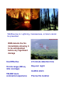
Wildfires due to Lightning, Carelessness, or Arson cannot
be prevented
WDS detects the fire
immediately allowing it
to be extinguished
before any significant
damage
Cost Effective
2.5 minute detection time
10 mile range (300 sq
mile coverage)
Day and night
Audible alarm
150,000 hours
commercial experience
Precise fire location
WFDS User Manual
© 2008-2010 Wildland Detection Systems LLC
All rights reserved. No parts of this work may be reproduced in any form or by any means - graphic, electronic, or
mechanical, including photocopying, recording, taping, or information storage and retrieval systems - without the
written permission of the publisher.
Products that are referred to in this document may be either trademarks and/or registered trademarks of the
respective owners. The publisher and the author make no claim to these trademarks.
While every precaution has been taken in the preparation of this document, the publisher and the author assume no
responsibility for errors or omissions, or for damages resulting from the use of information contained in this
document or from the use of programs and source code that may accompany it. In no event shall the publisher and
the author be liable for any loss of profit or any other commercial damage caused or alleged to have been caused
directly or indirectly by this document.
Printed: July 2010 in Sarasota, Florida, USA
Contents
5
Table of Contents
Foreword
Part I Introduction
7
10
1 Wildand
...................................................................................................................................
Fire Detection System
10
2 Simple
...................................................................................................................................
System Connection Diagram
11
3 Minimum
...................................................................................................................................
System Requirements
12
4 System
...................................................................................................................................
Features
13
5 System
...................................................................................................................................
Main Configuration
13
Part II Hardware & Software Installation
16
1 Sensor
...................................................................................................................................
Site
16
2 Software
................................................................................................................................... 16
3 Network
................................................................................................................................... 17
Part III Set UP
20
1 Camera
...................................................................................................................................
Installation
20
2 PTZ Settings
................................................................................................................................... 25
Device Settings
.......................................................................................................................................................... 26
PTZ Set Points.......................................................................................................................................................... 27
Auto Scan Settings
.......................................................................................................................................................... 32
Region Of Interest
.......................................................................................................................................................... 35
3 Analyzer
...................................................................................................................................
Settings
40
4 Alarm...................................................................................................................................
Settings
44
5 Google
...................................................................................................................................
Earth Set Up
46
6 Recording
...................................................................................................................................
Settings
47
Part IV Operation
52
1 Minimize
...................................................................................................................................
Button
53
2 Maximize
...................................................................................................................................
Button
53
3 Exit Program
................................................................................................................................... 53
4 Manual
...................................................................................................................................
Control
53
5 Window
...................................................................................................................................
View Panel
56
6 Google
...................................................................................................................................
Earth Usage
57
7 Playback
...................................................................................................................................
Records
59
Part V Remote Monitoring
64
1 Primary
...................................................................................................................................
Site
64
2 Remote
Site
...................................................................................................................................
65
© 2008-2010 Wildland Detection Systems LLC
5
6
WFDS User Manual
Part VI Off Line Analysis
Index
70
0
© 2008-2010 Wildland Detection Systems LLC
Foreword
7
Manual Organization
The WFDS user manual should answer most of your basic questions in the
following pages. However, since we cannot anticipate every question or
issue, please feel free to contact your supplier.
The manual is organized into 6 sections for ease of use.
Section I – Introduction
Provides general background information, system features, system
requirements and a brief overview on how the system works.
Section II – Installation
Minimum requirements and procedures for the installation of the hardware,
software and license acquisition.
Section III – SET-UP
This section provides the detail on setting all of the options and the logic for
WFDS. Once set these can be easily modified by the user in order to
address a change in circumstances or an improvement in performance
Section IV – Operation
Procedures and options for day to day and oversight operation of the system
Section V – Remote Operation
The system provides for remote monitoring and control of the system through
internet connection. This section provides the information necessary to set up
the remote.
Section VI – Off Line Analysis
At times it may be desirable to analyze incidents that have occurred previously
or to test the system with pre-recorded events. The methods necessary to
utilize this feature are included in this section.
© 2008-2010 Wildland Detection Systems LLC
Part
I
10
1
WFDS User Manual
Introduction
The WFDS system provides rapid detection of wildfires through visible range optical
cameras. The system is compatible with IP, analog and in most cases previously installed
cameras. This manual provides installation, set up and operating instructions for use with
IP cameras. For analog camera installation and set up or for use with existing cameras,
please contact your supplier for detailed instructions.
1.1
Wildand Fire Detection System
Wildfires are increasing in intensity, duration, and frequency
In the development of a wildfire, the first visible indication is the smoke. Trees and other
topographical factors hide the flames until the fire is grown and on the verge of being out of control.
In some cases there is smoke prior to any flames. Rapid detection, in the first 5 to 15 minutes,
will allow the fire to be extinguished quickly and with moderate equipment. Optical
Detection Systems meet the Rapid Detection requirement.
Wildland Detection Systems has developed an optical detection system with not only superior
performance but one that address:
Cost – both acquisition and operating
Excessive False Positives
Operating Complexity
WFDS is an early smoke detection program based on visualization and mapping of entered
information. The monitoring system entails video cameras installed in towers (detection towers)
with the video stream from each camera sent to the control center. The system analyses and
evaluates the image reducing it to its mathematical components and provides the system with the
capability to identify each small component, edge and movement within the image. Analysis of
successive images provides for identification of wildfire smoke and the differentiation from other
similar images.
The videos from all the interconnected towers can be shown on the computer monitor of the
coordinating WFDS Surveillance Center. The system progresses through multiple steps in the
detection process. One the smoke detection is confirmed by the system, an audible and visual alarm
is issued. The operator is then able to examine the alert area by manual control and zoom of the
camera, decide the appropriate response, issue notifications and/or dispatch suppression resources.
While the system can be programmed to issue automatic notifications to remote individuals or
systems, the final alarm/dispatch decision is reserved for the operator.
In order to provide robustness against the false alarms, the following strategy is implemented:
PTZ cameras are used that scan the area and hold for analysis at multiple stop points.
There is warning levels prior to an alarm
© 2008-2010 Wildland Detection Systems LLC
Introduction
11
Warning Level: Slow moving objects + color restrictions. Starts as yellow alarm and stays yellow
Alarm level : Slow moving objects + color restrictions+shadow elimination+wavelet analysis.
Starts as yellow alarm and becomes red alarm after some time.
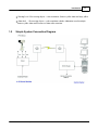
1.2
Simple System Connection Diagram
© 2008-2010 Wildland Detection Systems LLC
12
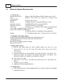
1.3
WFDS User Manual
Minimum System Requirements
1. Control Center
Operating System (OS):
Windows 2000(SP4),Windows XP(SP3),Windows Server 2003
CPU
Pentium 4, Core 2 Duo, Core 2 Quad, Core 2 Extreme, Xeon
3000/5000/7000
Motherboard
Intel chipset 945 or above
Memory
1 Gigabyte and above, recommend DDR2 type or newer
Hard disk (1) Drive C:
80 GB IDE/SATA/SCSI, recommend RAID5/6
Hard Disk (2) Drive D:
1 TB IDE/SATA/SCSI, for recording
Video Card
PCI Express x16, ATI Radeon Series graphic card with DirectX
9.0c or higher compatibility, hardware overlay and
DirectDraw
support, and a minimum of 64MB memory
128 MB video RAM is recommended for most applications
Monitor:
19 " LCD Display settings 1024 x 768 pixels and 16 or 32 bit color
2. Compatible video display adapter:
Nvidia Tnt/Tnt2 Geforce MX 400/440/4000/6600 Fx5200/5600 Series
ATI Radeon 7000/7200/7500/8500 /9000/9200 /9500/9600 Series
ATI X300/X700 series
Intel 845/865/915 integrated Extreme Graphics
MatroxG450/550/P750
3. Supported IP Cameras:
Axis 205, 206, 206M, 206W, 207, 207W, 207MW, 209FD, 210, 210A, 211, 211A,
211M, 211W, 212, 213, 214, 215, 231D, 232D, 240Q, 241Q, 241QA, 241S, 241SA,
242S, 243Q
JVC VN-C30U
Panasonic KX-HCM110 KX-HCM280A WJ-NT304 WJ-NT314 WV-NP472 WVNS324 WV-NF284 WV-NP1000 WV-NP1004 WV-NM100 WV-NP240 WVNP244 WV-NS202 WV-NW484 WV-NS954 WV-NW964
Pixord 1400 1401 4000
Sony SNC-P5 SNC-RZ25 SNC-RZ50 SNC-RX550 SNC-Z20 SNC-RZ30 SNCRX530
Vivotek 6122 6112 6112PTZ
SightLogix Visible Day/Night Sight Sensor
4. Communications
Point to Point Microwave, Point to Multipoint Microwave, ethernet, or fiber with a minimum
bandwidth of 1 Mb/sec.
© 2008-2010 Wildland Detection Systems LLC
Introduction
1.4
13
System Features
System features:
-Hardware support H.264 compression, low HDD cost
-Web access through LAN or WAN.
-Real time display (Up to 64 channel video input)
-Real time high-speed recording: Up to 30 fps per channel
-Synchronous audio recording (optional)
-Intelligent Analyzer
-Normal recording (continuous)
-GIS Map available (optional)
-Google Earth available (optional)
-Sending alarm message automatically.
-Sending alarm image to email box as attachment automatically
-Duplex mode (Recording while playback)
-Network support (Remote access via LAN, Ethernet, PSTN, ISDN, ADSL)
-P/T/Z/F & speed demo control on keyboard
-Search/playback by date/time directory (random-access)
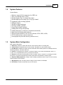
1.5
System Main Configuration
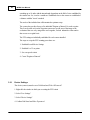
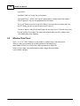
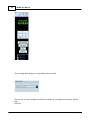
Main Interface Description:
1. Date/Time: shows the current date and time, which will be written in recording files.
2. Camera Name: The defined name of each camera. By default, it is the Camera number.
3. Info Marquee: IVADVR can output real time information about DVR System to Info Marquee bar like
Recording Cameras, Last Seen Alarm etc.
4. Preview: To preview all the channels’ or cameras’ videos in one screen simultaneously, press 1, 4,
9, 12H, 12V or 16 preview button then you will see all cameras.
5. Records: It shows the recording status of all the cameras. When a camera is in recording, the small
box which is on the left hand side of the camera name will be red otherwise it must be green.
6. Graphical E-Map (Optional): E-Map is used to display surveillance area in map, so user can easily
find the location of each camera.
7. GIS (Optional): User can easily find the location of each camera on GIS Maps.
8. PTZ Control: Control the movement of your PTZ camera.
© 2008-2010 Wildland Detection Systems LLC
14
WFDS User Manual
.
© 2008-2010 Wildland Detection Systems LLC
Part
II
16
2
WFDS User Manual
Hardware & Software Installation
The WFDS System consists of sensor sites, a control center and communications. Each control
center can support a network of up to 16 sensor sites. The specified optical range of the sensor is
10 miles. However, local climate conditions and terrain will affect the range. The system also
provides for 32 set points or observation points in the sensor rotation. Using these set points the
sensor can scan from 0 to 360 degrees.
Therefore one of the keys to successful operation of the system is a well planned layout of the sensor
locations.
2.1
Sensor Site
The sensor site will include the camera, a communications link and power for both the camera and
the communications node.
The camera selection must be from the list of pre approved cameras (section 1.3.3) or the user must
provide the proposed camera model to WDS for prior approval.
The camera enclosure must withstand the maximum harsh conditions experienced in the mounting
location. It is not desirable to remove the camera during winter and other non operational periods
and reinstall during the fire season.
The camera should contain a zoom function and a pan and tilt drive for proper operations. The
system requires that the pan and tilt drive be controlled with Pelco D protocol. The system then
utilizes 32 set points to cover the target area. Each set point consists of an elevation, azimuth and
zoom position. The area covered in each position is a factor including the lens field of view, pan, tilt
and zoom position. In order for the camera to provide detection a minimum area of 16 pixels by 16
pixels in the image must contain the smoke and/or fire portion of the image.
Camera selection and installation point should consider all of these factors
.
The system supplier will assist selection of power and communications components with the
minimum requirement that the communications component have a 1Mb/sec bandwidth.
The system is designed to hold at each set point for 20 seconds to evaluate the video stream. It
operates at the best quality level if there is no vibration in the camera. There fore the
installation of the camera needs to limit the possibility of vibration. If it is pole mounted it need to be
properly guy-wired. If mounted on another structure the mounting riser should be designed to limit
the vibration..
2.2
Software
1. Unpack the software by double clicking on the zip file
2. Click on the execute file, follow the instructions and the software will self install
3. Once installed an unlock code must be obtained for the software to operate. Your supplier will
© 2008-2010 Wildland Detection Systems LLC
Hardware & Software Installation
17
provide you with the instruction to obtain and install the unlock code.
2.3
Network
The system operates as a local area network. Each component in the network has a separate
address - computer, router, each of the up to 16 camera sites. All of the components must be in
the same network segment. How to assign network address for each component is supplied by the
component manufacturer with the exception of the computer and those instructions are supplied by
Windows.
In order to remotely provide assistance for the system, the user must obtain a internet
account with a static IP address.
© 2008-2010 Wildland Detection Systems LLC
Part
III
20
3
WFDS User Manual
Set UP
Each camera in the system, remote or in the LAN must be set up individually. The process includes
1.
2.
3.
4.
5.
6.
7.
Camera Installation
Set Point Selection
Analyzer selection and set up
Alarm settings
Record Settings
Regions of Interest
Event Location through Google Earth
These can be accomplished in any order after the camera is selected.
Once a camera is set up in the LAN, it can be monitored or controlled from any remote site through
an internet connection provide the LAN sight has a static IP address.
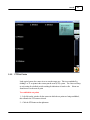
Step one is to move the curser to the window where the camera is to be installed and right click the
mouse
3.1
Camera Installation
Select "Live Settings" from first pull down menu
Select "Select Capture Device" from second pull down menu
© 2008-2010 Wildland Detection Systems LLC
Set UP
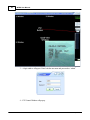
Select "IP Camera Selection"
Click OK
Select IP Camera type
© 2008-2010 Wildland Detection Systems LLC
21
22
WFDS User Manual
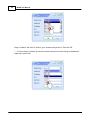
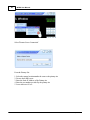
Image resolution* and enter IP Address, port, username and password. Then click OK.
* : To choose image resolution, the entered username and password must belong to administrative
rights at the camera side.
© 2008-2010 Wildland Detection Systems LLC
Set UP
23
If you get an connection error, please be sure that camera is connected and check IP Camera
Connection setting, like camera settings username and password are case sensitive.
If all needed fields are entered correctly, user window will appear
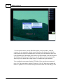
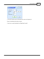
To change frame rate of live view choose “Live Settings->Capture Frame Rate..”. After that the
dialog in figure given below should appear. You can adjust the FPS of the camera from the control
labeled “Frame Rate:”. The capture frame rate should be set to between 10 and 20 FPS. Lower
frame rates are acceptable and will reduce the required transmission bandwidth.
© 2008-2010 Wildland Detection Systems LLC
24
WFDS User Manual
In Set Camera Name section, user can set a name to selected camera. After entering a name to
camera, entered name will appear top left of the camera screen. Optional
© 2008-2010 Wildland Detection Systems LLC
Set UP
25
Repeat for each camera in the network
3.2
PTZ Settings
In the typical system, the camera is set to scan the target area. This is accomplished by
defining 1 to 32 set points in the camera pan-tilt-zoom (PTZ) system. The camera will stop
at each setting for a defined period searching for indications of smoke or fire. If none are
found it moves to the next set point.
The system "looks" for smoke or fire in the area appearing in the screen image. Depending
on the elevation and zoom setting this area can be a triangle starting at the camera and
© 2008-2010 Wildland Detection Systems LLC
26
WFDS User Manual
extending up to 10 miles with the internal angle dependent on the field of view established by
the camera lens. Or, it can be a smaller are established close to the camera or established at
a distance with the "zoom" extended.
The needs of the individual site will determine the optimum setup.
The system also provides for up to five individual "Regions of Interest" for each set point.
These can be used to focus the detection system on a specific area of the image to the
exclusion of the rest or by using all five areas together, exclude industrial or other smoke
that occurs on a regular basis.
The PTZ setting are individually established for each camera installed.
The steps to set up the PTZ scanning procedures are:
1. Establish Overall Device Settings
2. Establish 1 to 32 set points
3. Set scan speed criteria
4. Create "Regions of Interest"
3.2.1
Device Settings
The device (camera) must be set to 2400 baud and "Pelco D Protocol"
1. Right click the window in which you are setting the PTZ criteria
2. Select "Live Settings"
3. Select "Device Settings"
4. Confirm 2400 baud and Pelco D protocol
© 2008-2010 Wildland Detection Systems LLC
Set UP
3.2.2
27
PTZ Set Points
In the typical system, the camera is set to scan the target area. This is accomplished by
defining 1 to 32 set points in the camera pan-tilt-zoom (PTZ) system. The camera will stop
at each setting for a defined period searching for indications of smoke or fire. If none are
found it moves to the next set point
To establish the set points
1 – Left click on the window for the camera in which the set points are being established;
this will make the PTZ camera selected.
2 – Click the PTZ button on the right menu.
© 2008-2010 Wildland Detection Systems LLC
28
WFDS User Manual
3 – A login window will appear. Enter both the user name and password as “admin”
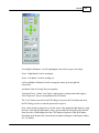
4 – PTZ Control Window will pop up.
© 2008-2010 Wildland Detection Systems LLC
Set UP
29
Focus Right-Left Buttons: Used for adjusting the camera focus to get a clear image.
Zoom – Right Button: Used for zooming in.
Zoom – Left Button: Used for zooming out.
Up-Down-Right-Left Buttons: Used for moving the camera up-down-right-left,
respectively.
Set Button: Used for “Saving” the preset position.
“Iris(Open/Close)”, “Menu”, and “Speed” options apply to analog cameras that support
Pelco-D protocol. They are not implemented for IP cameras.
The “Lock” button is used to lock the PTZ dialog. If you press the Lock button and close
the PTZ dialog, you have to enter the password to reopen it.
Now a park position is going to be set for the camera. After getting the right display by using
the focus, zoom and direction buttons, select a preset number for saving the preset from the
drop-down box. While holding down the CTRL button on keyboard, click the S Button.
Depending on the brand of the camera the preset number will appear on the display window
in 1-5 second(s).
© 2008-2010 Wildland Detection Systems LLC
30
WFDS User Manual
© 2008-2010 Wildland Detection Systems LLC
Set UP
31
All other presets can be configured in the same way. Each camera can have 32 presets.
Preset can be given names depending on the brand and model of the camera*.
*This feature is used via the menu of the camera. In order to use it, please refer to
the user manual of that PTZ camera.
Important Notes: When the camera is on auto mode if the user clicks any of the manual
controls (Right, Left, Up, Down, Zoom, Focus) in the PTZ window, the camera will stop the
auto mode and will let the user control the camera. In order to put the camera in auto mode
again, the user must select 55 from the drop-down box and click the G button. The camera
will automatically rotate after waiting at most 1500 milliseconds (pause duration).
Note set point #95 is not applicable to IP cameras.
© 2008-2010 Wildland Detection Systems LLC
32
WFDS User Manual
5. The ID and password can be changed
3.2.3
Auto Scan Settings
User can adjust Auto Pan settings of selected PTZ camera*.
In Auto Preset Settings Section, user can;
© 2008-2010 Wildland Detection Systems LLC
Set UP
33
Enable/Disable Auto Pan,
Set Pause Duration for each preset (in milliseconds),
Set Port, Baud Rate, Stop Bits, Parity Check, Data Bits
Select Presets
* User must adjust protocol setting at the camera side. Camera protocol settings are available in the
user manual provided by the camera manufacturer.
After setting the presets, automatic rotating settings of the camera must be configured:
1 – Right click to the camera for which the settings will be configured.
2 – From the context menu select Camera Settings > Auto Preset Settings
© 2008-2010 Wildland Detection Systems LLC
34
WFDS User Manual
3– In the opened window, enter the Baud Rate and the serial port number, which the
computer uses to communicate with the camera. Enter the pause duration, for which the
camera pauses at each preset, in milliseconds. Select the presets for which the camera will
rotate automatically by checking the boxes next to each preset number. Select the checkbox
for Enabling AutoPan and press OK button to exit. The camera will rotate automatically
from one preset to another after waiting at most 1500 milliseconds (pause duration).
You can adjust the preset names from the PTZ dialog. If you enter the preset name and
press “Set” only preset name is updated. If you press “Ctrl+Set” both preset position and
names are updated. You can see the entered preset names on the auto-scan dialog as well.
© 2008-2010 Wildland Detection Systems LLC
Set UP
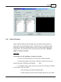
3.2.4
35
Region Of Interest
Region of Interest (ROI) provides the ability to have the analyzer function limited to a
portion of the video stream from the camera. This allows the user to eliminate nuisance
alarms that are created by vibrating structures, factory or other permanent smoke and
moving clouds. Up to five RoI's can be created for each preset location. The RoI is
unique to each preset location.
PROCESS
Create and save to file and image of each preset location
1. Use the "record" function and record a video clip of all preset locations
2. From the main window click "Records->Playback Control" choose the video
from the timestamps, it should open with mplayer
classic.
3. From mplayer classic seek to the preset you want to have the image for and then
save the image, "File->Save Image...".
a) Save the image to the WDS Program file folder
b) When saving, insure that you name the image such that you can correlate
© 2008-2010 Wildland Detection Systems LLC
36
WFDS User Manual
it with both the camera and preset location.
RoI's are created from the Auto Preset Settings Dialog
1. Right click in the location square of the camera in which you want to
create RoI's
2. Click "Camera Settings" the click "Auto Preset Settings"
3. Select
"Enable RoI"
The preset location for the RoI
"Open Image"
© 2008-2010 Wildland Detection Systems LLC
Set UP
37
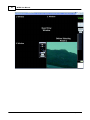
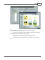
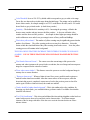
When Open Image is Selected, the Windows Explorer dialog is opened.
1. Select the drive and folder (s) where you previously stored the preset image and
select the image for the preset on which you are working
2. In the picture above a first present point's ROI picture is selected.
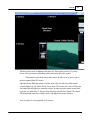
3. When BMP picture folder is installed for ROI, the windows screen seems like
below.
© 2008-2010 Wildland Detection Systems LLC
38
WFDS User Manual
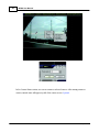
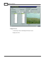
Configure RoI area
1. desired shape is drawn with holding the left button of mouse
Sample picture below.
© 2008-2010 Wildland Detection Systems LLC
Set UP
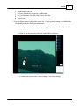
User can also create more than one ROI area for a present point. To do this,
again left button of mouse hold. Sample picture below.
,
© 2008-2010 Wildland Detection Systems LLC
39
40
WFDS User Manual
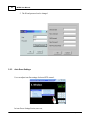
After ROI appointment is finished, appointments has to be saved with clicking
the Save ROI button.
Thus far ROI works for only about 1. present point. For other present points
same steps has to be repeated.
3.3
Analyzer Settings
The analyzer is the brains of the WFDS System. It provides two key modules and multiple
configurations for optimal set up in each applications There are two core detectors. The daytime
detector detects the rising smoke and the night detector detects the growing size of the fire image.
There is a warning level and prior to the alarm (yellow) and the alarm level (red) provides for both
an audible and visual alarm.
(Yellow) Warning level
stays yellow.
: Slow moving objects + color restrictions. Starts as yellow alarm and
(Red) Alarm level : Slow moving objects + color restrictions+shadow elimination+wavelet
analysis. Starts as yellow alarm and becomes red alarm after some time.
In order to establish analyzer settings:
Each individual camera in the network will have the analyzer settings
1. Right click on the window of the camera in order to set up its analyzer criteria.
2.Select Analyzers Settings then Select Analyzer.
© 2008-2010 Wildland Detection Systems LLC
Set UP
.
© 2008-2010 Wildland Detection Systems LLC
41
42
WFDS User Manual
Configure this screen by the following criteria:
"Enable Day Night Analyzer Switching" Check this box to have the analyzer automatically switch
between the day and night modes
"Don't Show Settings Dialog While in Live Mode" Check this box to prevent the "Settings" screen
from appearing on each start up.
"Don't Send Yellow Alarms to Remote" Check here to prevent yellow alarms from being
transmitted over the internet to remote locations
"Day Analyzer" Default is Forest Smoke Detector
"Night Analyzer" Default is Night Fire Detector
Select the camera Latitude and Longitude so the system can identify the time to switch to night file
and day smoke,
The "Calculate Sunrise/Sunset" button will determine the times automatically. These can also be
entered manually.
"Enable Daily Sunrise-Sunset Time Updates" Check this box to automatically recalculate sunrise/
sunset times
Click OK
This is the detail screen for settings
© 2008-2010 Wildland Detection Systems LLC
Set UP
43
Color Threshold: Is set to 128-255 by default which corresponds to gray-to-white color range.
Forest fires are almost always in this range during the initial stage. The settings can be modified to
detect darker smoke, for example settings to to 0-255 would detect all colors, and 0-128 would
detect black-to-gray colored smoke. (ie dark factory smoke)
Sensitivity - The default level for sensitivity is 80%. Increasing the percentage will make the
detector more sensitive and may increase the false positives. A decrease will make it less
sensitive and also decrease false positives. An example is that a higher percentage should be
used in wilderness areas and a lower percentage in areas of heavy traffic and buildings.
"Don't show yellow alarms" - The number of yellow warnings may be significantly greater that the
number of red alarms. The yellow warning on the screen may be a distraction. Select this
feature to hide the visual indication of the yellow warning visual on the screen. Note: the yellow
warning process will continue in the background.
THE FOLLOWING FEATURES INCREASE THE FILTERING TO REDUCE NUISANCE
ALARMS.. USE OF THESE FEATURES WILL INCREASE ELAPSED DETECTION
TIME
"Find Smoke Between Presets:" - The camera saves the current image of the preset to the
memory and when it returns to the preset for the second time, the saved image and current preset
image are compared for the existence of smoke.
"Reset when camera shakes" - This features causes the system to reset the background image in
memory due to camera vibration
"Return to alarm preset" - When red alarm is issued for a preset, possible smoke regions are
marked but the sound is not enabled. After that camera moves to the next preset, when the
detection in this preset is completed, camera moves back to the previous preset to check for
smoke again. If still a red alarm is issued, the sounds are enabled.
"Smoke should be brighter than background" - This is also similar to the color condition, for
detecting very dark smoke, you can disable this to get better results. For wildfire detection this
should be left selected.
"Use SVM classification" - This selects and additional decision making alogrithm set that has been
trained with a massive data set beyond basic smoke characteristics. It will then compare
elements of the live image with those of the data set to assist in detection decision to reduce
nuisance alarms.
© 2008-2010 Wildland Detection Systems LLC
44
3.4
WFDS User Manual
Alarm Settings
In the Alarm Settings Section, user can set an email address to send an email when alarm (Intelligent
Video Alarm type must set before the Alarm Settings) occurs, set the system to stop when an alarm
occurs and turn the audible alarm on and off.
1. Right click the window of the camera for which alarms are being set
2. Select Alarm Settings
3. Select E-Mail Settings
The stop and sound settings are selections on the lower level of the screen
"Pause on Alarm"- Works only in offline mode, it pauses the video when alarm occurs.
"Enable Sounds" - Turns audible alert on and off
© 2008-2010 Wildland Detection Systems LLC
Set UP
45
"Ask to Stop Scan on Alarm": Stops scan on alarm event. The software asks to start scan after 3
minutes, if no input is received from the user in 20 seconds the system restarts scan automatically.
If the user chooses not to restart scan the system asks to restart every 3 minutes.
The scan can be manually restarted by going to preset 55.
If user wants the system to send an e-mail then user should check the Send E-mail on Alarm Box.
© 2008-2010 Wildland Detection Systems LLC
46
WFDS User Manual
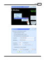
The user can also use an authenticated SMTP server for sending alarm messages. For example, to
use Gmail’s SMTP server, the server settings should be entered as shown in Fig.3. The “From”
address should be a working Gmail account and the “Username” and “Password” fields should be
the corresponding authentication details for this account. The system also supports SSL.
3.5
Google Earth Set Up
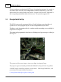
The WFDS system provides an automatic link to a Google Earth image system that allows the
operator to view on a topographic map the area that is being monitored by the camera.
This allows a quick determination of the fire coordinates and the surrounding access availability for
suppression crew dispatch.
The system can be programmed to show the area of the image on a large area map or to show just
the image area.
The system tracks the camera image as it moves providing a “moving map” image.
The program is generated manually and filed in the Wildland Fire Program Folder Google Earth.
A kml file* must be created for each preset on each camera. In the Google Earth Folder, each
preset/camera file is named with the convention as
Camera[CameraIndex]Preset[Preset Index].kml
© 2008-2010 Wildland Detection Systems LLC
Set UP
47
into the "Google Earth" folder.
For example for the 16th preset of 15th camera create and save
"Camera15Preset16.kml".
Camera indices are in the order they are arranged on the screen starting from 1.
For Google Earth to run when called inside vPlayer the selected camera should be in
AutoPan Mode. ("Camera Settings->Auto Preset Settings...").
* KML programming instructions are beyond the scope of this document. Free tutorials are
available on line from Google. It is expected that your supplier will provide initial programming.
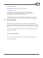
3.6
Recording Settings
The WFDS system provides the capability for recording of each cameras monitoring. The
recordings can be replayed by the WFDS system or any video player that supports a .avi format.
The record function is turned on and off by checking the "Record Continuously" box in the Recoding
dialog.
The record length for each file, allocated hard drive space, alarm only recording, and web image
transfer are all user selectable.
To set up the recording function:
In the window of the camera you are setting to record, right click and select camera settings
Then select recording settings
© 2008-2010 Wildland Detection Systems LLC
48
WFDS User Manual
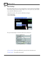
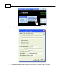
In the Recording Settings, user can set video recording codec *. Click … button to see codecs
that are installed on your system.
* : In codec section, user can see and select codecs that are installed on the user system
© 2008-2010 Wildland Detection Systems LLC
Set UP
49
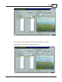
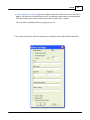
In FPS (Frame Per Second) Section, user can set recording FPS*.
* : This option available only IP cameras.
In Record Continuously Section, user turns the recording function on and off by cehcking the
boxx
In Record Only on Alarm Section, the systems will only record when there is an alarm and one
file after alarm. Both "Record Continuously" and Record only on alarm" boxes must be checked.
In Record File Length Section, user can set size of each record file
© 2008-2010 Wildland Detection Systems LLC
50
WFDS User Manual
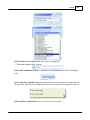
In Rec. (Recording) Root, user can select the folder that stores all the recorded files of selected
camera.
In Min HD Space (Minimum Hard Drive Space), user can specify the file size of the free space
in MegaBytes. When Hard Drive is full, system will delete oldest recorded file and continuous to
recording.
In Web Image Dir. (Directory) Section, user can select the folder that stores a single image. This
image will be refreshed in every Web Image Period milliseconds.
© 2008-2010 Wildland Detection Systems LLC
Part
IV
52
4
WFDS User Manual
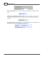
Operation
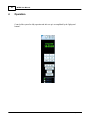
Control of the system for daily operation and after set up is accomplished by the "right panel
buttons"
© 2008-2010 Wildland Detection Systems LLC
Operation
4.1
Minimize Button
Press
4.2
button to maximize the main window.
Exit Program
Press
4.4
button to minimize the main window.
Maximize Button
Press
4.3
53
button to exit program.
Manual Control
When an alarm occurs, the operator may want to take control of the camera, examine the event
further and determine the coordinates of the event to dispatch suppression crews.
© 2008-2010 Wildland Detection Systems LLC
54
WFDS User Manual
To enlarge the viewing window to better examine the event see section 4.5
To determine to coordinates (provided Google Earth has been set up) see section 4.6
To take control of the camera pan tilt and zoom:
1 – Left click on the window for the camera in which the alarm occurred; this will make the
PTZ camera selected.
2 – Click the PTZ button on the right menu.
3 – A login window will appear. Enter both the user name and password as “admin”
© 2008-2010 Wildland Detection Systems LLC
Operation
4 – PTZ Control Window will pop up.
Focus Right-Left Buttons: Used for adjusting the camera focus to get a clear image.
Zoom – Right Button: Used for zooming in.
Zoom – Left Button: Used for zooming out.
Up-Down-Right-Left Buttons: Used for moving the camera up-down-right-left,
© 2008-2010 Wildland Detection Systems LLC
55
56
WFDS User Manual
respectively.
Set Button: Used for “Saving” the preset position.
“Iris(Open/Close)”, “Menu”, and “Speed” options apply to analog cameras that support
Pelco-D protocol. They are not implemented for IP cameras.
The “Lock” button is used to lock the PTZ dialog. If you press the Lock button and close
the PTZ dialog, you have to enter the password to reopen it.
In order to put the camera in auto mode again, the user must select 55 from the drop-down
box and click the Goto button. The camera will automatically rotate after waiting at most
1500 milliseconds (pause duration).
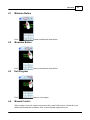
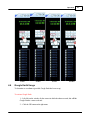
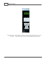
4.5
Window View Panel
Press 1-4-9-12V-12H-16 button to set the window’s partition mode of the main screen.
There are many types partition; the available partition is determined by the
total channels of card, you can select the suitable partition according to the
number of video inputs, the partition number which is bigger than total channel
is not available with gray.
© 2008-2010 Wildland Detection Systems LLC
Operation
1 view
4.6
4 view
9 view
16 view
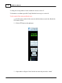
Google Earth Usage
To determine to coordinates (provided Google Earth has been set up)
To activate Google Earth
1 – Left click on the window for the camera in which the alarm occurred; this will link
Google Earth to camera selected.
2 – Click the GE button on the right menu.
© 2008-2010 Wildland Detection Systems LLC
57
58
WFDS User Manual
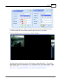
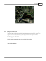
This will activate the Google Earth Feature and show on the moving map the image area covered by
the camera. As the operator moves from set point tset point the image will reposition.
© 2008-2010 Wildland Detection Systems LLC
Operation
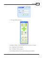
4.7
59
Playback Records
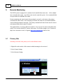
The system is provide the option to playback monitoring segments recorded by the system These
segments can also be played back by any video player that that will accept avi video files.
In order to playback while on line:
Left click on the corresponding camera view to playback the recordings.
Then click Records button.
© 2008-2010 Wildland Detection Systems LLC
60
WFDS User Manual
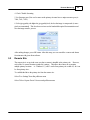
The recordings that belongs to corresponding camera are listed.
The user can view the recording of specific date and time by selecting the date and time from the
drop
down list.
© 2008-2010 Wildland Detection Systems LLC
Operation
© 2008-2010 Wildland Detection Systems LLC
61
Part
V
64
5
WFDS User Manual
Remote Monitoring
The WFDS system is equipped to be monitored and controlled from remote sites. In fact, multiple
sites can monitor the system. Any of these sites can also control the system. It is recommended that
clear procedures be established for control.
Remote monitoring and control requires that streaming be set up for each camera at the primary
command and control center. Once streaming is activated, the remote site can monitor individual
cameras through an internet connection. The primary command and control center must be connect
to the internet with a fixed or static IP address.
The application has a very basic client/server interface. You can view live cameras and alarms from
remote. You can also control PTZ cameras from remote. For all other settings we use Teamviewer
(http://www.teamviewer.com/) or Logmein (http://www.logmein.com/) (both are free).
5.1
Primary Site
Streaming is activated at the primary site for each individual camera.
1. Right click on the window of the camera in which streaming is to be activated
2. Select Camera Settings
3. Select Streamer Settings
© 2008-2010 Wildland Detection Systems LLC
Remote Monitoring
65
4. Check "Enable Streaming
5. Set Streamer port (Note each camera at the primary site must have a unique streamer port (ie
7900, 7901, 7902)
6. Select jpeg quality -the higher the jpeg quality level, the less the image is compressed (ie more
pixels are transmitted) This does however increase the bandwidth required for transmission and
slow the image transfer process
After making changes, press OK button. After this setup, user can watch live cameras and alarms
from internet with given client software.
5.2
Remote Site
The remote site is set up in the same way that a camera is installed at the primary site. However,
each of the 16 camera locations (windows) is unique. This allows the remote site to monitor
multiple primary locations. ie - Windows 1,2, and 3 can be from primary site a while 4,5 & 6 can
be from primary site c.
To establish the link to the primary site from the remote site:
Select "Live Settings" from first pull down menu
Select "Select Capture Device" from second pull down menu
© 2008-2010 Wildland Detection Systems LLC
66
WFDS User Manual
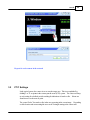
Select "Remote Server Connection"
From the Primary Site
1. Select the camera location number the same as the primary site
2. Do not check HIK server
3. Enter the Static IP Address of the Primary site
4. Enter the port number provided by the primary site
5. Leave timeout at 30 sec
© 2008-2010 Wildland Detection Systems LLC
Remote Monitoring
6. Select OK and the remote site will monitor the camera at the primary site.
Repeat for monitoring other primary locations.
Control can be assume through the local "Right Hand Controls"
© 2008-2010 Wildland Detection Systems LLC
67
Part
VI
70
6
WFDS User Manual
Off Line Analysis
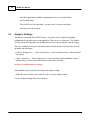
The offline analyzer enable the user to test settings and or other criteria by running the detection
systems with an existing video clip.
Prior to running the test the video clip must be recorded as or converted to:
1. AVI File Format
2. MJPEG, XviD or DivX video codec
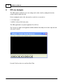
The offline application is a separate application Test APP.exe
The Test app is a single screen application with the addition of the ability to load video clips and with
video player controls.
From the Tool bar select view and check Real Time
© 2008-2010 Wildland Detection Systems LLC
Off Line Analysis
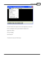
From the Tool Bar Select analyzer and select the settings that you want to test
Prior to to loading the video clip, insure that the live function is off.
Right Click in window
Select Live Settings
Select "Stop Live"
To load the video clip select File the Open
© 2008-2010 Wildland Detection Systems LLC
71
72
WFDS User Manual
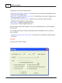
If you desire the record your output select "Recording Settings" (Note these are the output settings)
and then prior to running the video clip check "record output"
The video clip is controlled by the "standard" video control buttons at the bottom of the screen
© 2008-2010 Wildland Detection Systems LLC
73
Endnotes 2... (after index)
© 2008-2010 Wildland Detection Systems LLC
Back Cover


![[MANUAL] GuardNVR Installation Manual 4.4.0.0](http://vs1.manualzilla.com/store/data/005799040_1-22ffd5d438f0b0c95843f8ff9431bc2d-150x150.png)