1
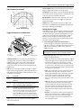
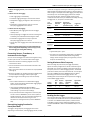
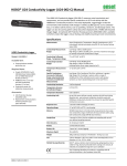
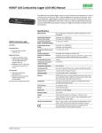
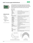
HOBO® 4-Channel Pulse Input
Data Logger (UX120-017x) Manual
The HOBO 4-Channel Pulse Input data logger records electronic pulses and mechanical or
electrical contact closures from external sensing devices. Using HOBOware®, you can easily
configure each of its four channels to monitor and record pulse, event, state, or runtime data in
a wide variety of applications, including tracking building energy consumption, monitoring
mechanical equipment, and recording water and gas flow rates. Plus, when combined with the
E50B2 Energy & Power Meter (T-VER-E50B2), this logger provides extensive power and energy
monitoring capabilities. There are two models of the HOBO 4-Channel Pulse Input data logger:
the UX120-017 stores more than 500,000 measurements while the UX120-017M holds more
than 4,000,000 measurements.
Specifications
Inputs
External Contact Input
Electronic solid state switch closure or logic driven digital signals to
24 V
Maximum Pulse Frequency
120 Hz
Maximum State, Event,
Runtime Frequency
1 Hz
Bits
4–32 bits depending on pulse rate and logging interval
HOBO 4-Channel Pulse
Input Data Logger
Maximum Pulses Per
Interval
7,863,960 (using maximum logging rate)
Driven Logic Signal
Input Low: ≤ 0.4 V; Input High: 3 to 24 V
Models: UX120-017
UX120-017M
Absolute Maximum Rating
Maximum Voltage: 25 V DC
Minimum Voltage: -0.3 V DC
Included Items:
Solid State Switch Closure
Input Low: < 10 KΩ; Input High: > 500 KΩ
Internal Weak Pull-Up
100 KΩ
Input Impedance
Solid state switch closure: 100 KΩ pull up; Driven signal: 4.5 KΩ
Minimum Pulse Width
Contact closure duration: 500 uS; Driven logic signal: 100 uS
Lockout Time
0 to 1 second in 100 ms steps
Edge Detection
Falling edge, Schmitt Trigger buffer
Preferred Switch State
Normally open or Logic “1” state
•
•
•
•
4 mounting screws
2 magnets
Hook & loop tape
4 terminal block connectors
Required Items:
• HOBOware Pro 3.2 or later
• USB cable (included with
software)
Accessories:
• Additional terminal blocks
(A-UX120-TERM-BLOCK)
• Lithium batteries (HWSB-LI)
Additional sensors and
accessories available at
onsetcomp.com.
Logging
Resolution
Pulse: 1 pulse, Runtime: 1 second, State and Event: 1 State or Event
Logging Rate
1 second to 18 hours, 12 minutes, 15 seconds
Time Accuracy
± 1 minute per month at 25°C (77°F) (see Plot A on next page)
Battery Life
1 year, typical with logging intervals greater than 1 minute and
normally open contacts
Memory
Memory
UX120-017: 520,192 measurements (assumes 8-bit)
UX120-017M: 4,124,672 measurements (assumes 8-bit)
Download Type
USB 2.0 interface
Download Time
30 seconds for UX120-017, 1.5 minutes for UX120-017M
Physical
Operating Range
Logging: -40° to 70°C (-40° to 158°F); 0 to 95% RH (non-condensing)
Launch/Readout: 0° to 50°C (32° to 122°F) per USB specification
Weight
149 g (5.26 oz)
Size
11.4 x 6.3 x 3.3 cm (4.5 x 2.5 x 1.3 inches)
Environmental Rating
IP50
The CE Marking identifies this product as complying with all relevant
directives in the European Union (EU).
14638-A MAN-UX120-017
HOBO 4-Channel Pulse Input Data Logger Manual
Terminal Blocks: There are 4 terminal blocks included with the
logger to plug into the inputs for connecting devices.
Specifications (continued)
Test Button: Press this button to activate the Activity Lights for
10 minutes to test for contact resistance or voltage signal in any
of the four input channels (see the LED table).
Mounting Holes: There are four mounting holes, two on each
side, that you can use to mount the logger to a surface (see
Mounting the Logger).
USB Port: This is the port used to connect the logger to the
computer or the HOBO U-Shuttle via USB cable (see Setting up
the Logger and Reading Out the Logger).
Plot A: Time Accuracy
Setting Up the Logger
Use HOBOware Pro to set up the logger, including selecting the
start and stop logging options, configuring the input channels
for specific sensor types, and entering scaling factors. It may be
helpful to set up the logger with a Delayed Start or a Button
Start first and then bring it to the location where you will
mount it to connect the external sensors/devices and test the
connections before logging begins.
Logger Components and Operation
Start/Stop Button
LEDs
1. Connect the logger and open the Launch window. To
connect the logger to a computer, plug the small end of the
USB cable into the side of the logger and the large end into a
USB port on the computer. Click the Launch icon on the
HOBOware toolbar.
USB Port
Important: USB communications may not function properly
at temperatures below 0°C (32°F) or above 50°C (122°F).
Inputs
One of Four
Terminal Blocks
Test Button
2. Select Sensor Type. Each of the input channels can be
configured to log the following:
Mounting Holes
• Pulse. This records the number of pulse signals per logging
interval (the logger records a pulse signal when the input
transitions to the logic low). There are built-in scaling
factors you can select for supported devices and sensors,
or you can set your own scaling when you select raw pulse
counts. You can also adjust the maximum pulse frequency
and lockout time as necessary.
Start/Stop Button: Press this button for 3 seconds to start or
stop logging data. This requires configuring the logger in
HOBOware with a Button Start and/or a Button Stop (see
Setting up the Logger). You can also press this button for
1 second to record an internal event (see Recording Internal
Logger Events).
LEDs: There are three types of LEDs on the logger to indicate
logger operation: Logging, Waiting, and Activity. Note that all
LEDs will blink when the logger is initially powered (i.e. when
the batteries are installed).
LED
Description
Logging
(green)
Blinks every 2 seconds when the logger is recording data.
Disable this LED by selecting the Turn Off LEDs option in
HOBOware.
Waiting
(orange)
Blinks every 2 seconds when awaiting a start because the
logger was configured with Start At Interval, Delayed
Start, or Button Start settings in HOBOware.
Activity
(red)
There is one Activity LED per input channel. Press the
Test button to activate all four Activity LEDs for 10
minutes to determine the state of the four input
channels. When the logger is recording data, the Activity
LED for the corresponding channel will blink at every
pulse signal. Note: If you press the Test button during
logging, then the Activity LED will remain illuminated for
any channel that has not been configured to record data.
• State. This records how long an event lasts by storing the
date and time when the state of the signal or switch
changes (logic state high to low or low to high). The logger
checks every second for a state change, but will only
record a time-stamped value when the state change
occurs. One state change to the next represents the event
duration.
• Event. This records the date and time when a connected
relay switch or logic low transition occurs (the logger
records an event when the input transitions to the logic
low). This is useful if you need to know when an event
occurred, but do not need to know the duration of the
event. You can also adjust the lockout time to debounce
switches.
• Runtime. This records the number of state changes that
happen over a period of time. The logger checks the state
of the line once a second. At the end of each logging
interval, the logger records how many seconds the line
was in the logic low state.
Inputs: There are 4 input channels to connect the logger to
external sensors/devices.
1-800-LOGGERS
2
www.onsetcomp.com
HOBO 4-Channel Pulse Input Data Logger Manual
3. Choose the logging interval, from 1 second to about 18
hours.
of channels configured, and the type of data being recorded. This
table estimates the logging duration based on recording event or
state changes on one input channel with logging set to stop when
the memory is full. To estimate logging duration for multiple
event or state channels, divide the logging duration by the
number of active channels. If you want to know exactly how long
the logger will run, use pulse or runtime modes.
4. Choose when to start logging:
• Now. Logging begins immediately.
• At Interval. Logging will begin at the next even interval.
• Delayed Start. Logging will begin at a date and time you
specify.
• Button Start. Logging will begin once you press the
Start/Stop logging button for 3 seconds.
5. Choose when to stop logging:
• When Memory Fills. Logging will end once the logger
memory is full.
Time
Between
Events
Approximate
Total Data
Points
Approximate
Logging Duration
(1 Year Battery Life)
Logger Part
Number
1 to 15
seconds
346,795
4 to 60 days
UX120-017
2,749,781
32 days to 1.3 years
UX120-017M
260,096
48 days to 2.1 years
UX120-017
2,062,336
1 to 16.6 years
UX120-017M
208,077
1.6 to 27 years
UX120-017
1,649,869
13 to 214 years
UX120-017M
173,397
22.5 to 360 years
UX120-017
1,374,891
17.8 to 285 decades
UX120-017M
16 seconds
to
4.2 minutes
• Never (wrapping). The logger will continue recording data
indefinitely, with newest data overwriting the oldest.
4.3 to 68.2
minutes
• Push Button. Logging will end once you press the
Start/Stop logging button for 3 seconds.
• Specific Stop Time. Logging will end at a date and time you
specify.
68.3
minutes to
18.2 hours
6. Select any other logging options as desired and finish the
launch configuration. Depending on the start type, verify
that the logging or waiting LED is blinking.
Notes:
• Typical battery life is 1 year.
Connecting Sensors, Transducers, or
Instruments to the Logger
• The logger can record battery voltage data in an additional
channel. This is disabled by default. Recording battery
voltage reduces storage capacity and is generally not used
except for troubleshooting.
You can connect the logger to an external sensing device using
the four input channels. To connect a device to the logger:
1. Follow the instructions and wiring diagrams in the user
manual for the device.
Setting Maximum Pulse Frequency
When recording raw pulse counts, the logger dynamically
adjusts its memory usage from 4 to 32 bits instead of a typical
fixed width. This results in the ability to store more data using
less space, which in turn extends logging duration. The default
pulse rate is 120 Hz, which is also the maximum. You can adjust
this rate in HOBOware (see the HOBOware Help for details).
Decreasing the rate will increase logging duration. The
following table shows examples of how pulse rate and logging
interval affect logging duration.
2. Connect the device to the terminal block as directed in the
device instructions.
3. Plug in the terminal block into one of the four inputs (labeled
1 through 4).
4. Press the Test button as needed to activate the Activity LEDs
and check whether the logger reads the pulse signal.
5. Configure logger launch settings if you have not already.
Notes:
• Be sure that all devices are connected before logging
begins. Any sensors/devices attached after logging begins
will not record accurate data.
Logging
Interval
Pulse
Rate
(Hz)
Number
of Bits
Required
Approximate
Total Data
Points
Approximate
Logging
Duration
• If connecting an E50B2 Energy & Power Meter
(T-VER-E50B2), you have the option to use the default
meter settings or your own custom settings.
1 minute
4
8
520,192
361 days
1 minute
50
12
346,795
240 days
1 minute
120
16
260,096
180 days
• If any channels have been configured to record raw pulse
counts or events in HOBOware, there is also an option to
specify lockout time. This can prevent false readings from
mechanical contact/closure bouncing. For more
information on setting lockout time, see the HOBOware
Help.
Reading Out the Logger
There are two options for reading out the logger: connect it to
the computer with a USB cable and read out it with HOBOware,
or connect it to a HOBO U-Shuttle (U-DT-1, firmware version
1.14m030 or higher) and then offload the datafiles from the
U-Shuttle to HOBOware. Refer to the HOBOware Help for more
details.
Determining Logging Duration for
Event/State Data
The logger’s storage capacity and logging duration varies
depending on several factors, including logging interval, number
1-800-LOGGERS
3
www.onsetcomp.com
HOBO 4-Channel Pulse Input Data Logger Manual
Recording Internal Logger Events
The logger records several internal events to help track logger
operation and status. These events, which are unrelated to
state and event logging, include the following:
Internal Event Name
Definition
Host Connected
The logger was connected to the computer.
Started
The Start/Stop button was pressed to begin
logging.
Stopped
The logger received a command to stop
recording data (from HOBOware or by
pushing the Start/Stop button).
Button Up/Button
Down
The Start/Stop button was pressed for
1 second.
Bad Battery
The battery level is 2.2 V (recorded even
when the battery channel has been
disabled).
Good Battery
The battery level returned to 2.4 V after a
Bad Battery event was marked.
Safe Shutdown
The battery level is 1.8 V; the logger shut
down.
Mounting the logger
There are three ways to mount the logger using the materials
included:
• Screw the logger to a surface with a Phillips-head
screwdriver and the four mounting screws, using the
following dimensions.
10.16 cm (4 inches)
the battery. Do not let the board get too hot. You should be
able to comfortably hold the board in your hand while drying it.
Note: Static electricity may cause the logger to stop logging.
The logger has been tested to 4 KV, but to be safe avoid
electrostatic discharge. For more information, search for “static
discharge” in the FAQ section on onsetcomp.com.
Battery Information
The logger is shipped with two AA alkaline batteries. You can
also use 1.5 V AA lithium batteries when deploying the logger in
cold environments. Expected battery life varies based on the
temperature where the logger is deployed and the frequency
(the logging interval and the rate of state changes and/or
events) at which the logger is recording data. A new battery
typically lasts one year with logging intervals greater than one
minute and when the input signals are normally open or in the
high logic state. Deployments in extremely cold or hot
temperatures, logging intervals faster than one minute, or
continuously closed contacts may reduce battery life.
The logger can also be powered through the USB cable
connected to the computer. This allows you to read out the
logger when the remaining battery voltage is too low for it to
continue logging. Connect the logger to the computer, click the
Readout button on the toolbar, and save the data as prompted.
Replace the batteries before launching the logger again.
To replace the batteries:
1. Disconnect the logger from the computer.
2. Unscrew the logger case using a Philips-head screwdriver.
3. Carefully remove the two batteries.
4. Insert two new AA batteries (alkaline or lithium) observing
polarity. When batteries are inserted correctly, all LEDs
blink briefly.
5. Carefully realign the logger case and re-fasten the screws.
4.57 cm
(1.8 inches)
• Attach the two magnets to the back of the logger and
then place the logger on a magnetic surface.
• Use the hook-and-loop tape to affix the logger to a
surface.
Protecting the logger
The logger is designed for indoor use and can be permanently
damaged by corrosion if it gets wet. Protect it from
condensation. If it gets wet, remove the battery immediately
and dry the circuit board with a hair dryer before reinstalling
1-800-LOGGERS (564-4377) • 508-759-9500
www.onsetcomp.com • [email protected]
WARNING: Do not cut open, incinerate, heat above 85°C
(185°F), or recharge the lithium batteries. The batteries may
explode if the logger is exposed to extreme heat or conditions
that could damage or destroy the battery cases. Do not dispose
of the logger or batteries in fire. Do not expose the contents of
the batteries to water. Dispose of the batteries according to
local regulations for lithium batteries.
HOBOware provides the option of recording the current battery
voltage at each logging interval, which is disabled by default.
Recording battery life at each logging interval takes up memory
and therefore reduces logging duration. It is recommended you
only record battery voltage for diagnostic purposes. Even with
the channel disabled, a bad battery event will still be recorded.
© 2011 Onset Computer Corporation. All rights reserved. Onset,
HOBO, and HOBOware are trademarks or registered trademarks of
Onset Computer Corporation. All other trademarks are the property
of their respective companies.
14638-A MAN-UX120-017