1
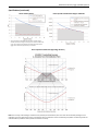
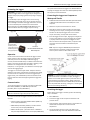
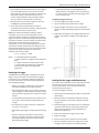
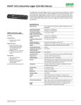
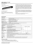
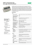
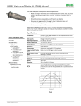
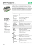
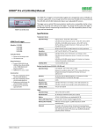
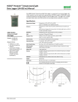
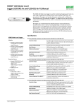
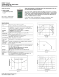
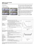
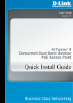
HOBO® U24 Conductivity Logger (U24-002-C) Manual
The HOBO U24 Conductivity logger (U24-002-C) measures actual conductivity and
temperature, and can provide specific conductance at 25°C and salinity with the
HOBOware® Conductivity Assistant. This easily deployable, rugged logger is ideal for
environments with relatively small changes in salinity (±5,000 µS/cm), such as saltwater
bays, or to detect salinity events, such as upwelling, rainstorm, and discharge events. This
logger can also be used to gather salinity data when deployed with a HOBO U26 Dissolved
Oxygen logger. An optional U2X Protective Housing accessory (HOUSING-U2X) is available
to further protect the logger, reduce fouling, and simplify mounting in harsh environments.
Specifications
HOBO Conductivity Logger
Model: U24-002-C
Included Item:
• Communications window
protective cap
Required Items:
• Coupler (COUPLER2-C) with
USB Optic Base Station (BASEU-4) or HOBO Waterproof
Shuttle (U-DTW-1)
• HOBOware Pro 3.2 or later
with the Conductivity
Assistant 2.1 or later
• Conductivity meter for
calibration measurements
Accessories:
• U2X Protective Housing
(HOUSING-U2X)
• Replacement communications
window protective caps
(U22-U24-CAP)
Measurements
Actual Conductivity, Temperature, Specific Conductance at 25°C
(calculated), Salinity (calculated using PSS-78, the Practical Salinity
Scale 1978)
Conductivity Measurement
Ranges
Low Range: 100 to 10,000 µS/cm
High Range: 5,000 to 55,000 µS/cm; see Plots A and B on next page
for salinity and specific conductance ranges
Conductivity Calibrated
Range - Temperature Range
5° to 35°C (41° to 95°F)
Conductivity Extended
Ranges
Low Range: 50 to 30,000 µS/cm
High Range: 1,000 to 55,000 µS/cm
(readings below these ranges reported as 0)
Temperature Measurement
Range
-2° to 36°C (28° to 97°F)
Specific Conductance
Accuracy (in Calibrated
Range using Conductivity
Assistant and Calibration
Measurements)
Low Range: 3% of reading or 50 µS/cm, whichever is greater
High Range: 5% of reading, in waters within a range of
±3,000 µS/cm of the calibration point; waters with greater
variation can have substantially greater error (see Plot C)
Conductivity Resolution
2 µS/cm (typical)
Temperature Accuracy
(in Calibrated Range)
0.1°C (0.2°F)
Temperature Resolution
0.01°C (0.02°F)
Conductivity Drift
Up to 12% sensor drift per month, exclusive of drift from fouling.
Monthly start- and end-point calibration should be used with
HOBOware Conductivity Assistant to achieve the specified Specific
Conductance accuracy
Response Time
1 second to 90% of change (in water)
Operating Range
-2° to 36°C (28° to 97°F) - non-freezing
Memory
18,500 temperature and conductivity measurements when using
one conductivity range; 14,400 sets of measurements when using
both conductivity ranges (64 KB total memory)
Sample Rate
1 second to 18 hrs, fixed or multiple-rate sampling with up to 8
user-defined sampling intervals
Clock Accuracy
±1 minute per month
Battery
3.6 Volt lithium battery
Battery Life
3 years (at 1 minute logging)
Maximum Depth
70 m (225 ft)
Weight
193 g (6.82 oz), buoyancy in freshwater: -59.8 g (-2.11 oz)
Size
3.18 cm diameter x 16.5 cm, with 6.3 mm mounting hole (1.25 in.
diameter x 6.5 in., 0.25 in. hole)
Wetted Housing Materials
Delrin®, epoxy, stainless steel retaining ring, polypropylene, Buna
rubber O-ring, titanium pentoxide (inert coating over sensor); all
materials are suitable for long-term use in saltwater
The CE Marking identifies this product as complying with all
relevant directives in the European Union (EU).
16844-C MAN-U24-002-C
HOBO U24 Conductivity Logger (U24-002-C) Manual
Specifications (continued)
Plot A: Salinity Range*
Plot B: Specific Conductance Range in Saltwater
* The Practical Salinity Scale 1978 (PSS-78) used to calculate salinity is
valid for salinities in the range of 2 to 42 ppt. For salinities outside of this
range, use the measured conductivity and temperature data from the
logger with a calculation appropriate for your salinities.
Plot C: Specific Conductance High-Range Accuracy
Note: The accuracy of the readings is relative to their proximity to the calibration point. The closer the conductivity reading is to the
calibration point, the higher the accuracy. The calibration point is measured in actual conductivity (not specific conductance), while the
calibrated data is provided in either specific conductance or salinity.
1-800-LOGGERS
2
www.onsetcomp.com
HOBO U24 Conductivity Logger (U24-002-C) Manual
The optical interface allows the logger to be offloaded without
breaking the integrity of the seals. The USB compatibility allows
for easy setup and fast downloads.
Protecting the Logger
IMPORTANT: This logger can be damaged by shock. Always
handle the logger with care. The logger may be damaged if it is
dropped. Use proper packaging when transporting or shipping
the logger.
Connecting the Logger to a Computer or
Waterproof Shuttle
Do not attempt to open the logger case or sensor housing.
Disassembling of the logger case or sensor housing will cause
serious damage to the sensor and logger electronics. There are
no user-serviceable parts inside the case. Contact Onset
Technical Support at 1-800-LOGGERS (1-800-564-4377) or an
authorized Onset dealer if your logger requires servicing.
Logger Case
Communications
window; place the
cap at right over the
window to protect it
during deployment
1. Follow the instructions that came with your base station
or Waterproof Shuttle to attach it to a USB port on the
computer.
2. Attach the coupler to the base station or shuttle.
3. Wipe off any residue or slime from the area of the logger
that will go into the coupler, including the communication
window. This will help the logger slide in and out of the
coupler more easily, and help with communication.
Sensor Housing
4. Insert the logger into the coupler, aligning the bump/arrow
on the coupler with the arrow on the logger. Be sure that it
is properly seated in the coupler. If the logger has never
been connected to the computer before, it may take a few
seconds for the new hardware to be detected by the
computer.
Sensor Face
Note: If you are using the HOBO Waterproof Shuttle as a
base station with a computer, briefly press the Coupler
Lever to put the shuttle into base station mode.
Do not scratch the sensor face
with a sharp tool.
Operation
An LED in the communications window of the logger confirms
logger operation. When the logger is logging, the LED blinks
once every one to four seconds (the shorter the logging
interval, the faster the LED blinks). The LED also blinks when the
logger is recording a sample. When the logger is awaiting a start
because it was configured to start “At Interval,” “On
Date/Time,” or “Using Coupler,” the LED blinks once every eight
seconds until logging begins.
The logger can record two types of data: samples and events.
Samples are the sensor measurements recorded at each logging
interval. Events are independent occurrences triggered by a
logger activity, such as Bad Battery or Host Connected. Events
help you determine what was happening while the logger was
logging.
WARNING: Do not leave the logger in the coupler for extended
periods of time. When connected to a coupler, the logger is
“awake” and consumes significantly more power than when it
is disconnected and considered “asleep.” Always remove the
logger from the Optic Base Station or HOBO Waterproof Shuttle
as soon as possible after launching, reading out, or checking the
status to avoid draining the battery.
Communication
To connect the logger to a computer, use either the Optic USB
Base Station (BASE-U-4) or HOBO Waterproof Shuttle
(U-DTW-1) with a coupler (COUPLER2-C).
Launching the Logger
IMPORTANT: USB 2.0 specifications do not guarantee
operation outside the range of 0°C (32°F) to 50°C (122°F).
Before deploying the logger in the field, perform the following
steps in the office:
To launch and read out the logger in the field, use one of these
methods:
1. Start HOBOware.
2. Connect the logger to the computer as described in the
previous section.
• Laptop computer with Optic USB Base Station (BASE-U-4)
and a coupler (COUPLER2-C)
• HOBO Waterproof Shuttle (U-DTW-1, Firmware Version
3.2.0 or later) and a coupler (COUPLER2-C)
3. Verify the status. Click the status button on the toolbar and
observe that the temperature is near the actual
temperature.
• HOBO U-Shuttle (U-DT-1, Firmware Version 1.14m030 or
later) with Optic USB Base Station and coupler (COUPLER2-C)
4. Launch the logger with the correct range. Refer to the
specifications on page 1 for both calibrated and extended
1-800-LOGGERS
3
www.onsetcomp.com
HOBO U24 Conductivity Logger (U24-002-C) Manual
ranges (the calibrated ranges are also printed on the logger
housing). The logger will not record readings outside of the
extended range selected. (For the U24-002-C, readings
below the extended range are reported as 0.) If in doubt on
the range needed for your deployment, or for environments
with wide fluctuations, select both ranges. This will shorten
the deployment duration from 18,500 samples to 14,400
samples per parameter (not logging battery voltage). See
the HOBOware User’s Guide or online help for details on
launching.
freshwater to remove any residual salt before taking your first
calibration readings.
Method 1:
Taking readings directly in the water (recommended for
locations with access for the field meter probe and with
conductivity that is stable)
1. If you have just deployed the logger, allow enough time for
the logger temperature to stabilize for the best accuracy
(approximately 15 minutes).
Note: Logging battery voltage is not essential because you can
check the battery using the Status screen at launch or readout
of the logger. Logging the battery voltage will reduce the
number of conductivity and temperature readings you can log.
2. Gently tap the logger to remove any bubbles from the
surface. Tug the cable if you cannot reach the logger itself.
3. Measure the temperature and actual conductivity with the
field meter, making sure the meter probe readings stabilize
per the meter’s specification. Record the values, time, and
location of the readings in a field notebook for use later in
the HOBOware Conductivity Assistant.
Taking Calibration Readings
It is important to take temperature and conductivity calibration
readings with a portable conductivity meter at both the
beginning (launchtime) and end of a deployment (readout)
because these readings are necessary for data calibration and
to compensate for any measurement drift during deployment.
The conductivity calibration readings should be the actual
conductivity without temperature compensation (not in specific
conductance at 25°C), and should be recorded in a notebook
with the time and location of the reading. You will use these
readings in the HOBOware Conductivity Assistant to calibrate
the readings for the corresponding data series offloaded from
the logger.
Method 2:
Taking readings in a jar (recommended for readings in wells or
in water with rapidly changing conductivity, such as areas
with saltwater and freshwater mixing)
1. Take a sample of water in a jar that is large enough to hold
both the logger and the probe from a portable conductivity
meter, leaving an inch of space between the probe and the
logger. For wells, use a bailer to obtain the water sample.
IMPORTANT: For the best accuracy, use a calibration
reading at the midpoint of the expected conductivity
range. This can be done either by taking a sample in the
middle of a tide cycle or by taking a sample at high tide
and then adding freshwater to reach the expected
midpoint. Always be sure to stir thoroughly to fully mix
the fresh and saltwater.
The calibration reading should be taken in the middle of the
expected range in the environment. For example, if the range
where the logger will be deployed is 20,000 µS/cm to 40,000
µS/cm, then the calibration reading should be taken at 30,000
µS/cm, which is the midpoint of that range (see Method 2 at
right for advice on how to get readings at the midpoint).
There are three methods for obtaining accurate calibration
readings. The first method involves placing the meter’s probe
into the water next to the logger. The second method involves
placing the logger and meter probe in a field water sample in a
jar. In both methods, the conductivity meter probe must be
close to the data logger—but not touching—so that it is
measuring water at the same conductivity and salinity as the
logger. The third method involves taking a sample back to the
office to measure with a meter there.
2. Leave the logger and the meter probe submerged in this jar
of water long enough so they reach temperature
equilibrium and the logger has logged at least three
readings (allow at least 15 minutes for the best accuracy).
(Three readings are necessary because this will help you
identify which readings were taken while the logger is in the
jar.)
3. Measure the temperature and actual conductivity with the
field meter. Record the values, time, and location of the
reading in a field notebook for use later in the HOBOware
Conductivity Assistant.
If the conductivity and salinity in the water where the logger is
deployed is stable and it is easy to reach the logger, then you
can obtain calibration readings by placing the probe directly
into the water next to the logger. However, taking calibration
readings in areas that have tidal and freshwater mixing is more
challenging due to the rapidly changing salinities. Similarly,
taking calibration readings in wells can also be difficult because
it may be hard to get the meter probe next to the logger. In
these instances, you should fill a jar with a water sample from
where the logger is deployed to take the calibration readings.
To obtain the water sample from a well or stilling well, you can
use a bailer with a diameter that is small enough to fit down
the well.
4. When using the Conductivity Assistant, look for the spot in
the data where there are three similar readings in a row
and link the last of those readings to the meter reading.
(The time you noted may be slightly different than the
logger time so looking for the three similar readings will
help identify the correct reading.) The Conductivity
Assistant uses that value to calibrate the specific
conductance and salinity readings for that data series.
Method 3:
Taking a sample back to the office in a sealable jar to measure
there (recommended for locations with conductivity that is
stable when you do not have a field meter or it is not
convenient to access the logger)
Note: Some salt residue may remain on the logger from factory
calibration. Carefully rinse the logger in distilled water or clean
1-800-LOGGERS
4
www.onsetcomp.com
HOBO U24 Conductivity Logger (U24-002-C) Manual
• Use the U2X Protective Housing (HOUSING-U2X) for
added protection to the logger in harsh environments or
to reduce the amount of light reaching the logger, which
helps to reduce fouling.
1. Place a sample of the water taken from next to the logger in
a jar and immediately seal it to ensure that none of the
water evaporates. This allows the specific conductance and
salinity of the sample to be maintained, which in turn
results in usable temperature and conductivity readings
when you measure it with the meter at a later time.
To deploy the logger at each site:
1. Launch the logger with a laptop or shuttle.
2. Write down the time you take the sample for use later in
the HOBOware Conductivity Assistant.
2. Take a calibration reading as described on page 4.
3. At the office, measure the temperature and actual
conductivity of the sample with a meter and write down the
values next to the time you noted in step 2.
3. Deploy the logger in the water (if it hasn’t already been
placed in the water) following the guidelines recommended
above.
Note: If you’ve taken the calibration readings in specific
conductivity, you can convert the readings back to actual
conductivity. Use the temperature readings from the meter or
logger to convert the conductivity reading following the specific
conductivity calculation used by your meter (consult the meter
documentation). If the meter uses a standard linear
compensation, you can use the following formula to convert it.
This equation calculates the electrical conductivity (Ye) from a
measured water temperature (T) and from a measured specific
conductance at 25°C (Cs) using the linear temperature
coefficient entered into the meter.
4. Repeat steps 1 through 3 for each logger deployed. Be sure
to take a new calibration reading for each logger that you
deploy.
Ye = Cs * (1 - ((25-T) * a / 100))
Where: Ye = Calculated Electrical Conductivity
T = water temperature in degrees C measured by the
meter
Cs = Specific Conductance measured by the meter
a = linear temperature coefficient (% / degrees C)
entered into the meter to calculate specific
conductance
Deploying the Logger
The HOBO U24 Conductivity logger is designed to be easy to
deploy in many environments. The small size of the logger is
convenient for use in small wells and allows the logger to be
mounted and/or hidden in the field. Follow these guidelines
when deploying the logger:
Reading Out the Logger and Maintenance
Your readout and maintenance schedule will be determined by
the amount of fouling at the site, sensor drift, and your
accuracy requirements. Two- to four-week maintenance
schedules are typically required.
• Make sure the logger is located where it will receive a
steady flow of the water that is being monitored.
• When deploying the logger in rivers, streams, and ponds,
insert the logger in a PVC or ABS pipe if possible. The PVC
pipe should have enough holes to ensure good circulation
of water.
To read out the logger in the field:
1. Calibrate the field conductivity meter before using it to take
field readings.
• To avoid bubbles collecting on the sensor, make sure the
sensor face is vertical and avoid sudden temperature
changes.
2. Measure the actual conductivity and temperature values
with the field meter using one of the calibration methods
on page 4 or 5.
• Do not place any conductive materials or metals within
2.5 cm (1 in.) of the sensor.
3. Remove the logger from the water (if it hasn’t already been
removed for the calibration measurement). Remove the
logger from the protective housing (if applicable) and
remove the protective cap.
• Avoid deploying the logger in freezing water with moving
ice.
4. Read out the data from the logger using a shuttle.
• Use the included cap to protect the communications
window in the logger from fouling and abrasion. Place
the protective cap over the communications window
before deploying the logger.
5. Relaunch the logger.
6. Clean the sensor (see the next section for more details).
7. Place the protective cap back on the logger and remount
the logger inside the protective housing (if applicable).
1-800-LOGGERS
5
www.onsetcomp.com
HOBO U24 Conductivity Logger (U24-002-C) Manual
8. Redeploy the logger in the water, and take another
calibration measurement.
3. If the results of steps 1 and 2 indicate this logger will work
for your application, then deploy this logger next to the DO
logger and use the resulting data file for salinity data.
Maintenance
The logger requires the following periodic maintenance to
ensure optimal operation:
• Clean the sensor. Mix several drops of dish detergent or
biodegradable soap in a cup of tap water with a clean
cotton swab. Clean the sensor face using the cotton swab
and then rinse the sensor with clean or distilled water.
Do not scratch the sensor face with a sharp tool.
• Check for biofouling. Biofouling and excessive marine
growth on the logger will compromise accuracy.
Organisms that grow on the sensor can interfere with the
sensor’s operation and eventually make the sensor
unusable. If the deployment area is prone to biofouling,
check the logger periodically for marine growth.
• Be careful of solvents. Check a materials compatibility
chart before deploying the logger in locations where
untested solvents are present. Refer to the specifications
for wetted housing materials on page 1.
Use HOBOware to calibrate data and convert to specific
conductance or salinity
1. Offload the most recent data files from the shuttle or
loggers to your computer.
2. Open a data file in HOBOware.
3. Use the HOBOware Conductivity Assistant to calibrate the
readings and adjust for drift. You will need to enter the field
meter conductivity and temperature readings and times
from the beginning and, optionally, the end of that segment
of the logger’s deployment. Refer to the Help for the
Conductivity Assistant for more details. Save your changes
to a project file.
4. Repeat steps 1 through 3 for all data files.
Using the Logger with a HOBO U26 Dissolved
Oxygen Logger
If you are deploying a HOBO U26 Dissolved Oxygen logger in a
location with changing conductivity, you will need a data file
with salinity or specific conductivity readings for the entire
deployment. The U24-002-C provides a convenient source for
this data, but it is not suitable for all environments. To
determine if this logger is adequate for salinity-adjusted DO in
your application:
1. Determine the potential conductivity error based on
maximum deviation from the field calibration point (see
Plot C on page 2 for reference).
2. Determine the effect of the conductivity error on the DO
accuracy, referring to the plot on the next page. For
conductivities within ±30,000 µS/cm, there will be less than
4% error added to the DO measurements (percent of the
DO reading in mg/L).
1-800-LOGGERS (564-4377) • 508-759-9500
www.onsetcomp.com • [email protected]
Battery Guidelines
• Battery Life. The battery life of the logger should be
three years or more. Actual battery life is a function of
the number of deployments, logging interval, and
operation/storage temperature of the logger. Frequent
deployments with logging intervals of less than one
minute, continuous storage/operation at temperatures
above 35°C (95°), and keeping the logger connected to
the coupler will result in significantly lower battery life.
For example, continuous logging at a one-second logging
interval will result in a battery life of approximately one
month. To obtain a three-year battery life, a logging
interval of one minute or greater should be used and the
logger should be operated and stored at temperatures
between 0° and 25°C (32° and 77°F).
• Battery Voltage. The logger can report and log its battery
voltage. If the battery falls below 3.1 V, the logger will
record a “bad battery” event in the datafile. If the datafile
contains “bad battery” events, or if logged battery
voltage repeatedly falls below 3.3 V, the battery is failing
and the logger should be returned to Onset for battery
replacement. Note that the logger does not have to be
recording the battery channel for it to detect bad battery
events. The logger will record these events regardless of
what channels are logged.
• Replacing the Battery. To have your logger’s battery and
sensor replaced, contact Onset or your place of purchase
for return arrangements. Do not attempt to replace the
battery yourself. Severe damage to the logger will result
if the case is opened without special tools, and the
warranty will be voided.
WARNING: Do not cut open, incinerate, heat above 100°C
(212°F), or recharge the lithium battery. The battery may
explode if the logger is exposed to extreme heat or conditions
that could damage or destroy the battery case. Do not dispose
of the logger or battery in fire. Do not expose the contents of
the battery to water. Dispose of the battery according to local
regulations for lithium batteries.
© 2013 Onset Computer Corporation. All rights reserved. Onset, HOBO, and HOBOware are
trademarks or registered trademarks of Onset Computer Corporation.
16844-C MAN-U24-002-C