1
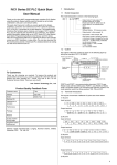
Design of Powerful Digital Servo-controller
VLADISLAV SKORPIL, JIRI STASTNY
Department of Telecommunications
Department of Automation and Computer Science
Brno University of Technology
Purkynova 118, 612 00 BRNO, Czech Republic,
CZECH REPUBLIC
Abstract: - The conception of control systems is at present based on the principle of decentralized
subsystems interconnected with the control centre through a communication channel. With this
arrangement it is easy to extend and modify the systems but, at the same time, the demands made on
the speed and capacity of transfer channels are higher. One of the companies that applied the idea of
decentralized system to the control of the positioning mechanism is the Swedish firm Atlas Copco.
Atlas DMC is a powerful digital servo-controller designed to control a large torque and great velocity
with various application possibilities. A standard logic unit provides for easy interconnection with
current control systems. The PL2 code is used for programming in the ProMOTION software. In the
basic version the Atlas system enables Off-line control, the direct control of axes is provided by Online control, and in the case of higher demands on the speed of communication a special
communication protocol, CAN, is used.
Key-Words: Control, simulation, ATLAS-system, servo-system, PL2code
1 Introduction
An intelligent current frequency-changer is
used to control position, and a synchronous
motor with permanent magnets on the rotor is
the driving unit. From the viewpoint of
versatile applicability an advantage of these
servo-controllers consists in their modularity
and the wide range of motors that can be
connected.
Synchronous
motors
with
permanent magnets are characterized by great
precision at the cost of a lower efficiency.
With the current trend of decreasing prices of
electronic products frequency changers are
becoming an affordable control tool.
2 Analysis of the functions of the
Atlas system
Atlas DMC represents a new series of
digital servo-systems with very efficient
integrated functions, built for systems that
need to control a high torque, velocity and
position in industrial facilities. The unit is
designed to control motors with permanent
magnets and output between 0.3 and 35 kW.
Three-phase motors with 230 V or 400
V ac power supply can be used. The third
possible power supply, the lowest, is singlephase 115 V ac supply of 0.3 to 35 kW,
currently in the stage of development. Units
with direct dc supply are also available. DMC
is conceived as a modular system and thus it
allows mounting the units side by side (all
modules are of the same height and depth) for
multi-axis applications. Atlas DMC is
produced in two versions:
- as an independent single-axis system with
an integrated power supply unit and a brake
module or
- for reasons of space economy and price
reduction it is supplied for multi-axis
applications without the integrated supply unit.
Power is then supplied from the central unit.
It was possible to achieve small
dimensions of the servo-amplifier by applying
the modern technology of switched sources.
Low power losses and a thorough thermal
design eliminated the need for external fan
cooling, which resulted in increased reliability.
Atlas DMC is based on the 16/8-bit Intel
980C196KC processor, which has a wide
range of functions. This enhances the DMC
potentials compared to other conventional R/D
converters. The DMC unit is made up of 4
items: power supply board, processor board,
I/O board and an optional “Integrated Power
Supply Board”.
The unit can be further extended by several
adjustable cards, which give the system much
flexibility. The power supply part utilizes
IGBTs (Insulated Gate Bipolar Transistor),
which provide the separation of ac supply
without using separating transformers. An
autotransformer can be used to adapt the
supply voltage. The output curve is sinusoidal
with 10 bits per sample, provided a standard
I/O board is used.
Measuring in two stages is currently used
with the usual transformation. Cyclic switched
signal with an efficiency of 96-98% and low
efficiency is used. Modular design reduces
production costs and physical dimensions.
Atlas DMC uses a simple speed feedback
as the feedback element. Position and
revolutions are read by a resolver integrated
directly on the motor. The speed and position
are given directly by the resolver.. The
standard version provides for two resolvers for
absolute positioning. This enables either
positioning in two axes with reliable rotation
or positioning of the master/slave type, where
the second resolver is the first to execute the
instructions. The second resolver can also be
used for compensating for slippage during
shifting, for setting the position manually, for
absolute multi-ROTATION positioning or as
another two analog inputs. Absolute measuring
eliminates the risk of impulse losses, which
can occur in the system of incremental sensor.
DMC can be used in high-speed applications.
The
integrated
function
of
the
programmable controller enables reading 12
(to 17) digital inputs, activating 6 (to 10)
digital outputs and two relay outputs. Two
programmable analog inputs can be used, for
example, to set externally the revolutions,
momentum, acceleration, etc. Two analog
outputs are used for setting the regulator or for
analog interfaces of further devices (they can,
for example, indicate the regulator deviation of
position, speed, momentum, etc.). Logic inputs
and outputs are made such that they are
resistant to industrial interference and shortcircuiting. The standard logic (24V) provides
for easy interconnection with current control
systems (PLC, industrial PC, etc.) without the
necessity of signal adaptation. A standard
feature of servo-amplifiers is the RAM 8 k
Byte back-up memory for storing the user
program.
3 Programming
Programming is conducted in the PL2 code in
the PproMOTION software running under the
Windows operating system. The Atlas DMC
PL2 code is an extension of the Atlas Copco
Controls Language, which was developed as
an interpretive language. Like other higher
programming languages it contains ifinstructions, creation of subprograms and
macros, arithmetic and logic operations. It also
provides for handling the inputs and outputs,
setting the internal timer, controlling the
interrupt, changing the parameters of servoamplifier (regulator), setting different modes of
operation
(synchronization,
flying
synchronization, non-linear transfer), etc. All
the instructions in the PL2 language can be
used On-line (with the programs running),
which simplifies the development and
debugging of the application program.
The ProMOTION environment includes
the ECT (Editor/Tester/Compiler) module,
which enables editing, compiling, copying and
testing the program.
This editor supports the PL2 syntax. If in
the course of compiling the PL2 code a syntax
or version error appears, the compiler will
mark the given part of the code and thus
initiate error correction.
Other modules of the ProMOTION
environment are: the FixIT installation module,
the module for actual execution of the PreSIZE
industrial programs with a database containing
data on motors, controller, power-supply units,
drives, mechanisms and linkages, and the
ProFILE module, which represents a graphics
instrument for experimenting with different
motion profiles. In real time, the ProFILE
module is interconnected with the PreSIZE
module for the analysis of the system being
designed.
4 Application possibilities
The Atlas system is an efficient means for
managing position control. It is suitable in
particular for applications where precision and
speed are required. It can be used with
advantage in repeated simple shifting
operations, where the control motor itself has
the function of a programmable automaton and
power electronics. It is very reliable for
combined movements, for example those of a
stowing machine or conveyer.
A great advantage of this system lies in the
possibility of setting the controller via the
program. The directly entered values of P.I.D.
constants provide for the best possible setting
of the control loop and thus for highly
satisfactory control. Creating a model of the
schematic of control loop the optimum values
of the constants being set can be obtained by
simulation.
4.1 Off-line control
The basic version of the Atlas system is
designed for type Off-line control. A program
is created in the development environment and
after compilation the resultant product is
transferred to the servo-amplifier. If any
parameters of position, speed or PID regulator
need to be adjusted, it is necessary to adjust the
source program and transfer it again into the
servo-amplifier. For the time of adjustment the
production is discontinued. This procedure can
be applied to simple movements in both lot and
mass production.
A change in the parameter can be solved
not only by overwriting the value. One
possible solution is to set the parameters
stepwise, using digital inputs. Admissible
values are redefined in the source language and
then they are only selected using an external
device (either manually or electronically).
Another possibility is setting the parameters by
means of analog inputs, where voltage can be
changed within 0 – 10V. In the case of slower
events the parameters can be changed by
setting the registers via the RS232 line, the
values being set, for example, every tenth of a
second or with an even longer period. To
determine position and speed, interpolation is
used between the periods.
4.2 On-line control
In the case of on-line control of axes it is
necessary to supply every millisecond data on
the position and speed (two data) of the given
axis in order to have a flowing and flexible
rapid motion. These data have to be transferred
in a 32-bit word. With these initial conditions
satisfied, a transmission channel of the
following capacity must be available: K > x
where K is the capacity in bit/s and x is the
number of axes that are being controlled. The
transmission capacity must be increased by the
transfer of control characters. To control the
manipulator in three axes, a minimum of 192
kbit would be necessary. Using a standard
series line, which in the Atlas system enables a
maximum speed of 9600 bit/s, this control is
not quite possible. This capacity can be used
for the transmission of a compiled program or,
for example, in series production to change the
position, revolutions, etc (between the
production of individual pieces). When
transmitting more values it is necessary to stop
the running program, change the setting and
then to restart with the changed parameters.
Because of the growing demands on the speed
of communication it is necessary to adopt
newer communication standards. CAN is one
of such satisfactory communication protocols.
4.3 CAN bus
The CAN (Controller Area Network)
communication protocol is based on the OSI
model complying with the ISO standard.
Thanks to its reliability and very good
hardware support on the level of
communication control units, CAN is
increasingly being used in various industrial
applications. The ATLAS Copco Controls
company also comes with a new module,
which replaces the original slow RS232
communication
by
a
type
CAN
communication.
In principle, the CAN communication is of
the multi-master type. The message transmitted
to the bus does not contain any information
about
the
target
station
(addressee
identification) but only the identification
number of the transmitting station, which is
different for every station. The identifier
includes not only the message content but also
the bus-access priority. This method enables
sending the message from one station to
another or to several stations at the same time
(broadcast). The actual transmission and
reception of the message frame and possible
repetition are performed by the respective
CAN control unit, which is only parameterised
from the CPU. The CAN communication
protocol does not require any physical
addressing of the target (reception) nodes.
A node that wants to transmit (CPU) sends
to the CAN controller the data to be
transmitted and the identifier of this node. The
whole message is then created by the CAN
control unit, which will provide bus access and
message dispatch. The moment the CAN
control unit recognizes that another node is
sending a message that has a higher priority
than its own message has, it will switch to the
reception mode.
All CAN control units can recognize the
correctness of received data. Some control
units are equipped with a means for message
filtering so that they only inform their
processor about the message received if the
message identifier is identical to the identifier
adjusted for reception. The CAN protocol
supports two types of message (frame), namely
CAN 2.0A and CAN 2.0B, the difference
between the two being in the length of
identifier (ID). CAN 2.0A has ID = 11 bits and
CAN 2.0b has ID = 29 bits. All the control
units used on one bus must support the
extended CAN 2.0B format.
In principle, the transmission of every
message is a “broadcast”. The message is
received in the CAN control units of all the
other nodes irrespective of whether the
receivers have their identifier filtering adjusted
or not. Every receiver that has received the
message error-free will send the active
(dominant) bit in the ACK array. This is to say
we are concerned with acknowledged
“broadcast”. This means that each receiver in
the network must respond to every transmitted
message and do so either in the ACK array or
by sending the error message.
For this kind of communication the Atlas
Copco company has developed a special
module which enables connection to world
communication standards. For the sake of
simpler but equally fast connection of the
external bus, Atlas Copco has developed an
internal CAN bus, which is used for internal
communication of individual modules.
5 Simulation model in the MatlabSimulink environment
In the elements that simulate the motor the
parameters of an SBL4-0400 motor were
entered. The position shift is set to one
revolution (8197 increments).
Simulation results:
Position vs. time, Revolutions vs. time,
Momentum vs. time, Proportional error vs.
time, Integration error vs. time, Derivative
error vs. time.
6 Conclusion
The application possibilities of the servocontroller are very broad. The Atlas system can
be modified to keep pace with the development
of new technologies and with increasing users’
demands. This is mainly evident on the
development of new communication standards.
The creation of a new module for
communication via the CAN bus and the
connection to buses of the type of Profibus,
Open-CAN, etc., have led to new application
possibilities. In the first place it is the
application possibility in systems with
continuous positioning in several axes
simultaneously. This in turn entails the
necessity of developing an environment for the
design and realization of control programs for
On-line control. But the tried and tested
application of DMC in both simple and
complicated applications of combined shifting
and driving should not be forgotten. To
provide all the necessary functions in these
cases the existing possibilities of this system
are fully satisfactory.
Acknowledgement
This research was supported by the grants:
No 102/03/0434 Limits for broad-band signal
transmission on the twisted pairs and other
system co-existence The Grant Agency of the
Czech
Republic
(GACR)
No CZ 400011(CEZ 262200011) Research of
communication systems and technologies
(Research
design)
No IS 432 124 (2124/2003/F1) Modernizing
and innovation of telecommunication services
education (grant of the Czech Ministry of
Education,
Youth
and
Sports)
References:
[1] ATLAS DMC: User’s Manual 2.0. Atlas
Copco, 1995
[2] ATLAS DMC: User’s Manual, First
Edition, Atlas Copco, 1994
[3] TG drivers: Digital Servocontrollers Atlas
Copco . Atlas Copco, 1995.