1
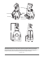
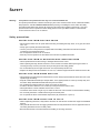
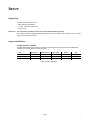
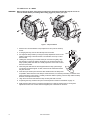
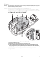
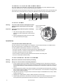
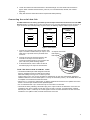
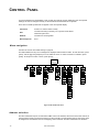
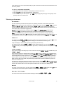
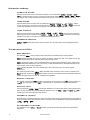
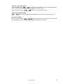
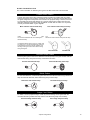
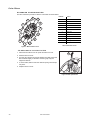
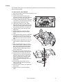
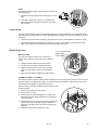
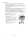
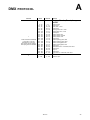
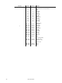
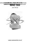
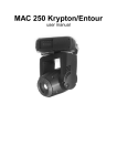
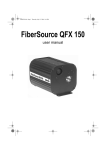
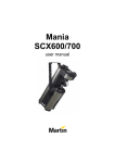
MX-10 Extreme user manual pan/tilt arm AC & data sockets front cover bolts control panel mounting bracket cooling fan 735 340 98 217 ©2002-2008 Martin Professional A/S. Information subject to change without notice. Martin Professional A/S and all affiliated companies disclaim liability for any injury, damage, direct or indirect loss, consequential or economic loss or any other loss occasioned by the use of, inability to use or reliance on the information contained in this manual. The Martin logo, the Martin name and all other trademarks in this document pertaining to services or products by Martin Professional A/S or its affiliates and subsidiaries are trademarks owned or licensed by Martin Professional A/S or its affiliates or subsidiaries. P/N 35000117, Rev. I CONTENTS Introduction ................................................................................................................................. 5 Features ................................................................................................................................. 5 About this manual .................................................................................................................. 5 Safety ............................................................................................................................................. 6 Safety precautions ................................................................................................................. 6 Setup .............................................................................................................................................. 7 Unpacking .............................................................................................................................. 7 Lamp installation .................................................................................................................... 7 AC power ............................................................................................................................... 9 Installation ............................................................................................................................ 10 Connecting the serial data link ............................................................................................. 11 Control Panel ............................................................................................................................ 12 Menu navigation .................................................................................................................. 12 Address selection ................................................................................................................. 12 Tailoring performance .......................................................................................................... 13 Information readouts ............................................................................................................ 14 Test and service utilities ....................................................................................................... 14 DMX-512 control ...................................................................................................................... 16 Lamp power ......................................................................................................................... 16 Effect position ...................................................................................................................... 16 Speed control ....................................................................................................................... 17 Optical configuration ............................................................................................................. 18 Gobos .................................................................................................................................. 18 Color filters ........................................................................................................................... 20 Prism .................................................................................................................................... 21 Service ......................................................................................................................................... 22 Lamp replacement ............................................................................................................... 22 Mirror replacement ............................................................................................................... 22 Cleaning ............................................................................................................................... 22 Lubrication ........................................................................................................................... 23 Replacing fuses ................................................................................................................... 23 Updating software ................................................................................................................ 24 DMX protocol ...........................................................................................................................................25 Control menu ...........................................................................................................................................29 Error messages ......................................................................................................................................32 Troubleshooting ....................................................................................................................................33 PCB connections ..................................................................................................................................34 Specifications - MX-10 Extreme ...................................................................................................35 NOTES Disposing of this product Martin™ products are supplied in compliance with Directive 2002/96/EC of the European Parliament and of the Council of the European Union on WEEE (Waste Electrical and Electronic Equipment), as amended by Directive 2003/108/EC, where applicable. Help preserve the environment! Ensure that this product is recycled at the end of its life. Your supplier can give details of local arrangements for the disposal of Martin products. I NTRODUCTION Features Thank you for selecting the Martin MX-10 Extreme. Some of the many features include: • • • • • • • • • • • • • • • efficient, 3000 hour, 250 watt discharge lamp 12 interchangeable dichroic colors 8 interchangeable indexed-rotation gobos interchangeable 3-facet rotating prism motorized focus full-range dimming fast blackout and strobe effects fast and accurate 16-bit mirror movement advanced low-noise motor control coated optics user-installable firmware switch-selectable power supply settings power factor correction integrated mounting bracket and floor stand easy-to-clean cooling fan About this manual Please check the Martin web site at http://www.martin.dk for the latest product software and documentation. Comments or suggestions regarding this document may be e-mailed to [email protected] or posted to Martin Professional A/S Olof Palmes Allé 18 DK-8200 Aarhus N, Denmark Attn: Service Department Please review the important safety precautions in this manual before installing and operating the fixture. Introduction 5 SAFETY Warning! This product is for professional use only. It is not for household use. This product presents risks of lethal or severe injury due to fire and heat, electric shock, ultraviolet radiation, lamp explosion, and falls. Read this manual before powering or installing the fixture, follow the safety precautions listed below and observe all warnings in this manual and printed on the fixture. If you have questions about how to operate the fixture safely, please contact your Martin dealer or call the Martin 24-hour service hot line at +45 70 200 201. Safety precautions PROTECTION FROM ELECTRIC SHOCK • Disconnect the fixture from AC power before removing or installing the lamp, fuses, or any part, and when not in use. • Always ground (earth) the fixture electrically. • Use only a source of AC power that complies with local building and electrical codes and has both overload and ground-fault protection. • Do not expose the fixture to rain or moisture. • Refer any service operation not described in this manual to a qualified technician. PROTECTION FROM UV RADIATION AND LAMP EXPLOSION • Never operate the fixture with missing or damaged lenses and/or covers. • When replacing the lamp, allow the fixture to cool for at least 15 minutes before opening the fixture or removing the lamp. Protect your hands and eyes with gloves and safety glasses. • Do not stare directly into the light. Never look at an exposed lamp while it is lit. • Replace the lamp if it becomes defective or worn out, or before usage exceeds the maximum service life. PROTECTION FROM BURNS AND FIRE • Never attempt to bypass the thermostatic switch or fuses. Always replace defective fuses with ones of the specified type and rating. • Keep all combustible materials (for example fabric, wood, paper) at least 0.1 meter (4 inches) away from the fixture. Keep flammable materials well away from the fixture. • Do not illuminate surfaces within 0.3 meters (12 inches) of the fixture. • Provide a minimum clearance of 0.1 meters (4 inches) around fans and air vents. • Never place filters or other materials over the lens or mirror. • The exterior of the fixture can get very hot. Allow the fixture to cool for at least 5 minutes before handling. • Do not modify the fixture or install other than genuine Martin parts. • Do not operate the fixture if the ambient temperature (Ta) exceeds 40° C (104° F). PROTECTION FROM INJURY DUE TO FALLS • When suspending the fixture, verify that the structure can hold at least 10 times the weight of all installed devices. • Verify that all external covers and rigging hardware are securely fastened and use an approved means of secondary attachment such as a safety cable. • Block access below the work area whenever installing or removing the fixture. 6 MX-10 Extreme SETUP Unpacking The MX-10 Extreme comes with: • MSD 250/2 lamp (installed) • 3-meter, 3-wire IEC power cable • user manual Important! Cut and remove the cable tie from the tilt motor bracket before operating. The packing material is carefully designed to protect the fixture during shipment - always use it or a custom flight case to transport the fixture. Lamp installation COMPATIBLE LAMPS A Philips MSD 250/2 lamp is included. The MX-10 Extreme lamp options are shown in the table below. Installing any other lamp may damage the fixture. Lamp Average life Replace before Color Temp. Output P/N Osram HSD 250 2000 hr 2500 hr 6000K 68 lm/W 97010103 Philips MSD 250/2 3000 hr 3300 hr 8500K 72 lm/W 97010100 Philips MSD 200 2000 hr 2200 hr 5600K 67 lm/W 97010106 Table 1: Lamp comparison Setup 7 TO INSTALL A LAMP WARNING! When replacing the lamp, disconnect the fixture from AC power and allow the lamp to cool for at least 15 minutes before proceeding. Wear safety goggles to protect your eyes. Figure 1: Lamp installation 1. Remove the 2 screws labelled “Lamp replacement” and pull out the lamp socket. 2. If changing the lamp, remove the old lamp from the socket. 3. Pre-adjust the lamp socket by turning the 3 lamp adjustment screws to the middle of their range. There should be 2 mm between each cap nut and the fixed disk. 2mm 4. Holding the new lamp by its ceramic base (do not touch the glass), align the small pin on the lamp with the small hole in the socket and insert the lamp squarely. Make sure that the 4 small projections on the base contact the face of the socket. 5. Clean the glass bulb with the cloth supplied with the lamp, particularly if your fingers touched the glass. A clean, lint-free cloth wetted with alcohol may also be used. 6. Insert the tip of the lamp into the fixture with as little twist in the lamp wires as possible. When the base of the lamp is inside the fixture, turn the lamp assembly so that the arrow points towards the control panel. Carefully locate the reflector opening, which is deep within the lamp chamber, and fully insert the lamp. 7. Align the screw holes and fasten the lamp access plate with 2 screws. 8. If replacing the lamp, reset the lamp hour and lamp strike counters as described on page 14. 9. Strike the lamp (after setup is complete) and adjust it for optimum performance by turning the 3 adjustment screws one at a time until the brightest part of the beam is centered. 8 MX-10 Extreme AC power Warning! For protection from electric shock, the fixture must be grounded (earthed). The power supply shall have overload and ground-fault protection. Important! Verify that power supply settings match the local AC supply before use. The MX-10 Extreme is factory configured for 230 V / 50 Hz operation. If your AC power supply is different, the fixture must be configured for the local voltage and frequency. Always use the voltage settings that are equal to or next highest to your AC supply. TO CONFIGURE FOR LOCAL AC POWER voltage cy en qu fre Figure 2: Power supply settings 1. Disconnect the fixture from power. 2. Remove the 4 cover screws with a 5 mm hex key. Lift off the front cover. 3. Locate the selection switches and the settings label, which is by the color wheel. Move the voltage switch to the setting that is equal to or higher than the local AC voltage. If your voltage falls between 2 settings, always select the higher voltage. For example, if the AC voltage is 215 V, use the 230 V setting instead of 210 V. 4. Move the frequency switch to the setting that matches the local AC frequency: 50 or 60 Hz. 5. Replace the cover. Setup 9 TO INSTALL A PLUG ON THE POWER CABLE The power cable must be fitted with a grounding-type cord cap that fits your power distribution system. Consult an electrician if you have any doubts about proper installation. • Following the cord cap manufacturer’s instructions, connect the yellow and green wire to ground (earth), the brown wire to live, and the blue wire to neutral. The table below shows some pin identification schemes. Wire Pin Marking Screw color brown live “L” yellow or brass blue neutral “N” silver yellow/green ground green Table 2: Plug wiring TO APPLY POWER Warning! Important! The power cables must be undamaged and rated for the electrical requirements of all connected devices. Powering through a dimmer system can damage the fixture. AC input & fuse holder Data input Data output 1. Verify that the supply cable is undamaged and rated for the current requirements of all connected devices. 2. Plug the prepared power cable into the AC socket and a grounded AC power supply. Installation LOCATION AND ORIENTATION The MX-10 Extreme may be installed in any orientation. It can be fastened directly to a suitable surface, hung with a rigging clamp, or placed directly on a level surface. For safe operation, install the MX-10 Extreme in a location where • • • • • the mirror is at least 0.3 meters (12 inches) away from any illuminated surface the fixture is at least 0.1 meters (4 inches) away from combustible materials the fixture is protected from rain and moisture there is at least 0.1 meters (4 inches) clearance around the fan and control panel there are no flammable materials nearby TO RIG OR MOUNT THE MX-10 EXTREME Warning! Block access below the work area before proceeding. Warning! Always use a secure means of secondary attachment. 1. If using a rigging clamp (not included), verify that it is undamaged and can bear at least 10 times the fixture’s weight. Bolt the clamp securely to the bracket with a grade 8.8 (minimum) M12 bolt and lock nut, or as recommended by the clamp manufacturer, through the 13 mm hole in the center of the mounting bracket. 2. If fastening the fixture directly, verify that the hardware (not included) and mounting surface can bear at least 10 times the fixture’s weight. The four 6.2 mm holes and/or the 13 mm hole in the mounting bracket may be used to fasten the fixtures. 3. Verify that the structure can support at least 10 times the weight of all installed fixtures, clamps, cables, auxiliary equipment, etc. 4. Working from a stable platform, clamp or fasten the fixture to the structure. 5. Install a safety cable that can hold at least 10 times the weight of the fixture through/over the support and anywhere through the aluminum pan/tilt arm that does not interfere with mirror movement. 10 MX-10 Extreme 6. Loosen the swivel locks and tilt the fixture to the desired angle. Turn the swivel locks clockwise to tighten. When a handle reaches its limit, pull it out, turn counterclockwise, release, and continue tightening. 7. Verify that the fixture meets the location requirements listed previously. Connecting the serial data link The MX-10 Extreme has locking 3-pin data input and output sockets that are wired for use with DMX devices with pin 1 to shield, pin 2 to cold (-) and pin 3 to hot (+). As some devices have 5-pin connectors, or 3-pin connectors with reversed polarity on pins 2 and 3, the following adaptor cables may be required. 5-pin to 3-pin Adaptor 3-pin to 5-pin Adaptor Male Female Male Female Male Female 1 2 3 4 5 1 2 3 1 2 3 1 2 3 4 5 1 2 3 1 2 3 P/N 11820005 P/N 11820004 3-pin to 3-pin Phase-Reversing Adaptor P/N 11820006 Figure 3: Cable adaptors 1. Connect the controller’s output to the fixture’s data input. For a DMX controller with 5-pin output, use a cable with a 5-pin male and a 3-pin female XLR connector. AC input & fuse holder Data input Data output 2. Connect the output of the fixture closest to the controller to the input of the next fixture. If connecting a fixture with pin 3 hot to a fixture with pin 3 cold, use a phase-reversing adaptor. 3. To terminate the link, insert a male 120 Ω XLR termination plug in the output of the last fixture. TIPS FOR BUILDING A SERIAL LINK • Use shielded twisted-pair cable designed for RS-485 devices: standard microphone cable cannot transmit DMX data reliably over long runs. For links up to 300 meters (1000 ft.) long, you can use 24 AWG, low capacitance, 85-150 ohm characteristic impedance, shielded cable with 1 or more twisted pairs. For runs up to 500 meters (1640 ft.) use 22 AWG cable. Use an amplifier if the serial link exceeds 500 meters. • Never use a “Y” connector to split the link. To split the serial link into branches use a splitter such as the Martin 4-Channel Opto-Isolated RS-485 Splitter/Amplifier. • Do not overload the link. Up to 32 devices may be connected on a serial link. • Terminate the link by installing a termination plug in the output socket of the last fixture on the link. The termination plug, which is simply a male XLR connector with a 120 ohm, 0.25 watt resistor soldered between pins 2 and 3, “soaks up” the control signal so it does not reflect back down the link and cause interference. If a splitter is used, terminate each branch of the link. Setup 11 CONTROL PANEL You set the address and personalities, read out data, and execute service utilities from the control panel. Settings can also be changed remotely via the serial link with the Martin MP-2 uploader. There are four small symbols that can appear in the control panel display: Tick/check Power is on and the fixture is ready Disc The fixture is writing to memory. Do not power off the fixture while this symbol is lit. Network The fixture is receiving DMX Wrench/spanner Error Menu navigation See also the control menu table starting on page 29. The DMX address and any error messages are displayed after the fixture resets. To enter the menu, press [menu]. Use the [up] and [down] keys to move within the menu. To select a function or submenu, press [enter]. To escape a function or menu, press [menu]. Address/ Messages Figure 4: MX-10 Extreme menu Address selection The MX-10 Extreme requires 13 channels for DMX control. The address, also known as the start channel, is the first channel used to receive instructions from the controller. For independent control, each fixture must be assigned its own address and non-overlapping control channels. Two MX-10 Extremes can share the 12 MX-10 Extreme same address if they are to respond identically: they will receive the same instructions and individual control will not be possible. TO SET THE DMX ADDRESS 1. Apply power to the MX-10 Extreme. Press [menu] to enter the main menu. 2. Select using the [up] and [down] keys. Press [enter]. 3. Select an address (start channel) from to using the [up] and [down] keys. Press [enter]. Press [menu] to return to the main menu. Tailoring performance MOVEMENT The MX-10 Extreme provides the three options for optimizing movement to suit different applications. , the pan and tilt invert menu, allows you to swap the pan and tilt channels ( → ), invert pan movement ( → ), and invert tilt movement ( → ). These options can be useful in situations where you want some fixtures to mirror the performance of others with the same DMX address, or when fixtures are not oriented as programmed. , the pan/tilt speed menu, provides 2 settings: and . is best for most applications. provides better performance in applications where speed is most important. , the shortcuts setting, determines whether the color and gobo wheels scroll past open when changing positions. When set to , the wheels can “take a shortcut” and scroll through open when this is the shortest path to the next position. The wheels do not scroll past open when is set to . DISPLAY The display menu ( → ) determines whether the display remains lit or not. Select to have the display remain lit, or to extinguish the display two minutes after the last key press. To flip the display for easier reading, press [up] and [down] simultaneously. The display intensity setting ( → ) controls display brightness. You can select for automatic dimming of the display using the built-in light sensor, or manually select an intensity level from to . LAMP POWER There are two settings that modify lamp control: Automatic Lamp On ( → ) and DMX Lamp-Off ( → ). There are three options for automatic lamp control: , , and . When is , the lamp remains off until a lamp-on command is received from the controller. When is , the lamp strikes automatically after the fixture is powered on. When is set to , the lamp strikes automatically when the fixture receives DMX data, and it extinguishes automatically 15 minutes after DMX data is lost. When ALON is either ON or DMX, lamp strike timing is determined by the fixture address to prevent all lamps from striking at once. The DMX Lamp-Off setting effects how the lamp can be turned off. When is , lamp power can be switched off by sending a DMX value from 248 to 255 on channel 1 for five seconds. When is , the lamp-off command will not work unless special conditions are met. Refer to the DMX protocol. RESET The fixture can be reset from the controller if DMX reset ( → ) is . If DMX reset is , this command will not work unless special conditions are met. Refer to the DMX protocol. DEFAULT SETTINGS The fixture can be reset to its factory default settings by selecting → → Control Panel 13 Information readouts POWER-ON HOURS Read the total number of hours the fixture has been on since fabrication ( → → → ), and the number of hours on since the counter was last reset ( → → → ). This can be used to track maintenance intervals. Press [up] for 5 seconds while displayed to reset. LAMP HOURS Read the total number of lamp hours since fabrication ( → → → ), and the number of lamp hours since the counter was last reset ( → → → ). Reset this counter after installing a new lamp. Press [up] for 5 seconds while displayed to reset. LAMP STRIKES Read the total number of lamp strikes ( → → → ), and the number of lamps strikes since the counter was last reset ( → → → ). Reset this counter when installing a new lamp. Press [up] for 5 seconds while displayed to reset. FIRMWARE VERSION → displays the firmware version number. The firmware version is also displayed briefly at startup. Test and service utilities DMX READOUT The DMX log ( ) menu provides useful information for troubleshooting control problems. displays the DMX refresh rate in packets per second. Values lower than 10 or higher than 44 may result in erratic performance, especially when using tracking control. displays the quality of the received DMX data as a percentage of packets received. Values much below 100 indicate interference, poor connections, or other problems with the serial data link that are the most common cause of control problems. displays the DMX start code. Packets with a start code other than 0 may cause irregular performance. The remaining options under display the DMX values received on each of the 13 channels, from (shutter, channel 1) to (effect speed, channel 13). If the fixture does not behave as expected, reading the DMX values can help you troubleshoot the problem. MANUAL CONTROL The manual control menu ( ) provides commands for turning the lamp on ( ), turning the lamp off ( ), and resetting the fixture ( ). It also permits you to position and move individual effects. EFFECTS TEST The test sequence ( → ) runs through all effects to provide a quick check of fixture performance. Note: the test sequence does not automatically strike the lamp. Use → and → to control lamp power. Press [menu] to stop the test. FEEDBACK TOGGLE Magnetic sensors monitor the positions of the color wheel, gobo wheel, and rotating gobos. If they detect an error, the shutter closes while the effect resets. This feature can be disabled by turning effects feedback off ( → → ). ADJUSTMENT POSITIONS The adjustment menu ( → ) provides commands for positioning effects during mechanical adjustment. 14 MX-10 Extreme EFFECT CALIBRATION With the calibration menu ( → ), effect positions can be fine-tuned with a software-defined offset value to compensate for small misalignments or differences between fixtures. The default offset command ( → ) erases any offsets stored in memory. CIRCUIT BOARD TEST → executes a routine designed for testing the main circuit board. For service use only. UPLOAD MODE The upload mode command ( → ) prepares the fixture for a software update. This command is not necessary, however, as upload mode is engaged automatically by the uploader. Control Panel 15 DMX-512 CONTROL This section briefly describes the DMX-controllable effects. See also the DMX table starting on page 25 and the DMX chart on the back cover. Lamp power LAMP-ON Unless automatic lamp strike is enabled, lamp power remains off until a lamp-on command is sent from the controller. Note: A peak of electric current that can be many times the operating current is drawn for an instant when striking a discharge lamp. Striking many lamps at once may cause a voltage drop large enough to prevent lamps from striking or draw enough current to trip circuit breakers. If sending lamp-on commands to multiple fixtures, program a sequence that strikes lamps one at a time at 5 second intervals. LAMP-OFF The lamp can be turned off from the controller by sending the lamp-off command on channel 1 for 5 seconds. The lamp cannot be restruck for 8 minutes after being turned off. Note that the lamp-off command may be disabled by the DMX Lamp-Off personality setting. Effect position RESET If an effect loses its indexing and fails to move to programmed positions, the fixture can be reset from the controller by sending the “Reset” command on channel 1 for 5 seconds. Note that the DMX reset feature may be disabled by the DMX Reset personality setting. DIMMER / SHUTTER The mechanical dimmer/shutter system provides full, high-resolution dimming, “instant” open and blackout, random and variable strobe effects, and random and variable pulses in which the dimmer snaps open and slowly dims or snaps closed and slowly opens. Shutter, strobe, and pulse effects are selected on channel 1. The intensity level is selected on channel 2. COLOR The color wheel can be scrolled continuously - allowing for split color effects - or in steps, and rotated randomly or continuously in both directions at different speeds. GOBO ROTATION AND SELECTION The MX-10 Extreme has 8 indexed-rotation gobo positions plus an open position. Gobos can be indexed (positioned at a defined angle), rotated continuously, or rotated and shaken (bounced). The gobo and the type of movement are selected on channel 4 and the index angle or rotation speed are selected on channel 5. The gobo wheel also rotates continuously in both directions at variable speed. FOCUS The beam may be focused from approximately 2 meters (6.5 feet) to 20 meters (65 feet). ROTATING PRISM The prism may be inserted and removed from the light path. It rotates in both directions at varying speeds. 16 MX-10 Extreme PAN AND TILT Mirror pan and tilt are controlled on channels 8 to 11. The course control channel sets first 8 bits (the most significant byte or MSB), and the fine channel sets the second 8 bits (the least significant byte or LSB) of the 16-bit control byte. In other words, the fine channel fine-tunes the position set by the course channel. Speed control TRACKING CONTROL Tracking control is enabled by setting the speed channels (12 and 13) to one of the tracking values listed in the DMX table, typically 0. With tracking control, the speed at which effects move is determined by the cross-fade time between two positions or scenes. The controller divides the move into steps and updates the fixture with small changes at the rate required to achieve the fade. The fixture “tracks” the changes and averages them with a digital filter algorithm to provide smooth movement. VECTOR CONTROL With vector control, movement speed is determined by the speed values on channels 12 and 13. This provides a way to control speed on controllers without cross-faders. Vector control also provides smoother movement, particularly at slow speeds, with controllers that send slow or irregular tracking updates. When using vector control, the cross-fade time must be 0. BLACKOUT When “blackout while moving” is selected on channels 12 or 13, the shutter closes when the effect moves to make the transition invisible. The shutter opens when the movement is complete. PERSONALITY OVERRIDES Channel 12 provides tracking values that allow you to override the pan/tilt speed personality setting. Channel 13 provides tracking values that allow you to override the shortcuts setting. See the DMX table for details. DMX-512 control 17 OPTICAL CONFIGURATION Gobos The MX-10 Extreme accepts eight metal or glass gobos with an outside diameter of 22.5 mm and a maximum image diameter of 17 mm. Complete gobo specifications are listed on page 36. STANDARD GOBO CONFIGURATION The MX-10 Extreme provides 8 gobos as shown below. 8 1 2 . 7 3 6 4 Position Gobo 1 Eclipse 2 Shark bar 3 Phat fan 4 Tail spin 5 Sun 6 Triangle 7 Oriental fire 8 Paint mix Table 3: Standard gobos 5 Figure 4: MX-10 Extreme gobo wheel CUSTOM GOBOS For optimum performance, custom glass gobos for the MX-10 Extreme should be made with the text, logo, and similar artwork reversed on the coated side. Gobo types and dimensions are specified on page 35. TO REPLACE A GOBO 1. Disconnect the fixture from AC power and allow it to cool. 2. Remove the front cover. 3. Turn the gobo wheel to access the desired position. Squeeze the ends of the retention spring together and remove. Push the gobo out from the back and remove. 4. Orient the gobo as shown on page 19 and insert. Secure the gobo with the retention spring. 5. Replace the cover before applying power. Figure 5: Gobo replacement 18 MX-10 Extreme GOBO ORIENTATION The correct orientation for different gobo types in the MX-10 Extreme is shown below. Coated Glass Gobos Coated glass gobos in the MX-10 Extreme should normally be installed with the coated surface facing away from the lamp, towards the front lens, to minimize internal reflections in the glass and give best sharpness and contrast in the projected image. However, if there is an unusually high risk of heat damage on a custom coated gobo, install it with the more reflective side facing towards the lamp regardless of which side is coated. If in any doubt, consult your Martin dealer or gobo supplier. More reflective side towards lamp If there is a risk of gobo overheating and damage, turn the more reflective side of a coated gobo towards the lamp. Less reflective side away from lamp The less reflective side of a coated gobo will absorb less heat if it faces away from the lamp. To determine which side of a gobo is coated, hold an object up to it. On the uncoated side, there is a space between the object and its reflection and the edge of the gobo can be seen when looking through the glass. Uncoated side Coated side Textured Glass Gobos Textured glass gobos in the MX-10 Extreme sit most squarely in the gobo-holders with the textured side facing away from the lamp, towards the front lens. Smooth side towards lamp Textured side away from lamp Metal Gobos To avoid heat distortion, install metal gobos with the more reflective side facing towards the lamp and the less reflective, darker side facing away from the lamp. Reflective side towards lamp Dark side away from lamp Image / text Gobos To obtain a correct projected image, install asymmetrical image or text gobos with the reversed side facing towards the lamp and the true side facing away from the lamp. Reversed image towards lamp True image away from lamp cba abc Optical configuration 19 Color filters STANDARD CONFIGURATION The MX-10 Extreme provides 12 dichroic color filters as shown below. 3 4 Position 5 6 2 7 1 8 12 9 11 10 Color 1 CTC 2 Yellow 603 3 Blue 104 4 Pink 312 5 Green 206 6 Blue 108 7 Red 301 8 Magenta 507 9 Blue 101 10 Orange 306 11 Dark green 12 Purple 502 Table 4: Standard colors Figure 6: MX-10 Extreme color TO REPLACE A COLOR FILTER 1. Disconnect the fixture from AC power and allow it to cool. 2. Remove the front cover. 3. Turn the color wheel to access the desired color filter. Press the filter forwards slightly to release it and then grasp it by the edges and remove. B A 4. To insert a filter, slide it under the retention spring until it snaps into place. 5. Replace the front cover. Figure 6: Filter replacement 20 MX-10 Extreme Prism The standard 3-facet prism can be replaced with optional five- and nine-facet prisms. See Accessories on page 36 for part numbers. TO REPLACE THE PRISM 1. Disconnect the fixture from AC power and allow it to cool. 2. Remove the front cover. 3. Remove the three prism module screws. There are two screws on the color wheel side and one screw on the gobo wheel side. 4. Unfold the flexible wire retainers on each side of the chassis, just behind the prism module. 5. Unplug the color wheel sensor cable. 6. Lift the prism module out of the chassis. When the lower prism motor nears the color wheel sensor, tilt the prism module forward to avoid damaging the sensor connection pins. 7. Unplug the motors and remove the prism rotation belt. 8. Working through the round hole, lift the retention spring off the back of the prism holder. 9. Rock the prism gently from side to side while pulling lightly to work the prism out of the bearing. Do not use force. If the holder gets stuck, press it back into the bearing and try again. 10. Gently insert the replacement prism into the rotation bearing. Install the prism rotation belt. 11. Place the module prism-down on a clean surface with the prism centered in the round hole. Hold the unbent end of the retention spring in the prism holder groove with one hand and work the spring into the groove with your other hand. 12. Plug in the prism motors: the longer of the two cables is for the larger of the two motors. 13. Tilt the bottom motor away from the color wheel sensor as you insert the module into the fixture. When the motor is clear of the sensor connection pins, bring the module back to vertical and press it down into position so that the module tabs seat in the chassis slots. 14. Fold the flexible wire retainers over the cables on each side. Reconnect the color wheel sensor cable. 15. Fasten the prism module to the chassis with three screws. 16. Replace the front cover before applying power. Optical configuration 21 SERVICE The MX-10 Extreme requires regular maintenance to keep performing at their peak. Excessive dust, grease, and smoke fluid buildup degrades performance and causes overheating and damage that is not covered by the warranty. The maintenance schedule will depend on the application and should be discussed with your Martin distributor. Refer any service that is not described here to a professional technician. Warning! Removing covers while the fixture is powered on exposes dangerous live electrical circuits, hot surfaces, and a lamp under high pressure. Disconnect the fixture from AC power and allow it to cool before removing any cover. Lamp replacement Lamp life will vary; the rated life is an average figure that is based on the manufacturer’s test cycle. For maximum lamp life, avoid excessive strikes and always allow the lamp to burn for at least 5 minutes before turning it off. To reduce the risk of lamp explosion, which may damage the fixture, never exceed the lamp’s rated life (2000 hours) by more than 25 percent. Replace the lamp when: • it strikes with difficulty or not at all, or is in any other way defective • usage exceeds the manufacturer’s “replace before” hours. See Table 1. Refer to page 8 for the lamp replacement procedure. Mirror replacement No adjustment is required after replacing the mirror as long as you do not loosen the tilt motor shaft adaptor. TO REPLACE THE MIRROR 1. Remove the two screws that fasten the mirror bracket to the tilt motor shaft adaptor with a 3 mm hex key and remove the mirror. 2. Apply a drop of threadlock such as Loctite 243 to each screw. 3. Place the new mirror assembly on the shaft adaptor and fasten securely. Cleaning OPTICAL COMPONENTS Use care when cleaning optical components. The surface on dichroic filters is achieved by means of special multi-layer coatings and even small scratches may be visible. Residues from cleaning fluids can bake onto components and ruin them. 1. Allow the components to cool completely. 2. Wash dirty lenses and filters with isopropyl alcohol. A generous amount of regular glass cleaner may also be used, but no residues may remain. 3. Rinse with distilled water. Mixing the water with a small amount of wetting agent such as Kodak Photoflo will help prevent streaking and spotting. 4. Dry with a clean, soft and lint-free cloth or blow dry with compressed air. 22 MX-10 Extreme FAN To maintain adequate cooling it is important that the fan be cleaned regularly. 1. Remove the fan by pulling out the locking pins on each side. 2. Clean with a soft brush, vacuum, or compressed air. 3. Place the fan back in position and press in the locking pins to secure. Lubrication Use only silicone lubricant, Martin P/N 37302003 (500 ml) or P/N 37302004 (200 ml, in applicator bottle). No other lubricant is approved for use. When applying lubricant, always remove excess and do not get oil on other parts. 1. Check the focus mechanism and apply a drop of lubricant to the 3 metal slides if movement is rough. 2. Lubricate the rotating-gobo bearings if movement is rough on slow rotation or if they become noisy. Apply a few drops of oil to each bearing from the lamp side of the wheel. Replacing fuses AC input & fuse holder Data input MAIN FUSE The main fuse holder is built in to the mains input socket. Never replace the fuse with one of a different rating! Data output 1. Unplug the mains cable from the input socket. 2. Pry open the fuse holder and remove the fuse. 3. Replace the fuse with one of the same type and rating. The fuse rating is listed on serial number label. 4. Close the fuse holder and replace the mains cable. POWER SUPPLY FUSES There are two fuses for the low-voltage power supplies located on the printed circuit board. If one or more of the green LEDs on the PCB does not light, one of these fuses may be blown. If all three LEDs are lit, the low-voltage power supplies are functioning correctly. Have the fixture serviced by a Martin service technician if the problem persists. 1. Disconnect the fixture from AC power. 2. Remove the front cover. 3. Remove the four screws that fasten the control panel assembly. Move the display assembly out of the way to access the PCB. 4. Carefully remove and check the two fuses located in the top-left corner of the PCB (see page 34). Replace as necessary with fuses of the same size and rating (see page 35). 5. Install the control panel and the front cover. Service 23 Updating software The latest MX-10 Extreme firmware is available from the support area of the Martin web site at www.martin.dk. It can be installed via the serial data link using a supported Martin uploader such as the MP-2, or via a LightJockey 4064 ISA DMX interface. Note: Intermediate control systems such as the Martin Lighting Director (MLD) and the Martin Matrix must be bypassed when updating fixture software via the DMX link. These systems do not relay the update code correctly because it is not a DMX-compliant signal. NORMAL UPDATE To update fixture software, connect an upload device to the fixture just as you would connect a DMX controller and perform a DMX mode upload as described in the uploader’s documentation. There is no need to isolate the MX-10 Extreme fixtures from other types of fixture on the serial link. When the upload is completed (and when booting up) the MX-10 Extreme performs a check-sum test of the flash memory and then resets. If the firmware is corrupted a check-sum error ( ) occurs. A few seconds later the fixture displays and is ready for a new DMX-mode upload. In the unlikely event that a software upload is interrupted, the fixture must be powered off for at least 10 seconds to force the check-sum test. You can repeat the DMX-mode upload as soon as is displayed. BOOT SECTOR UPDATE If the normal update procedure fails or the software update notes call for a boot-sector update, install new software as follows. 1. Disconnect the fixture from AC power. 2. Remove the front cover. 3. Remove the four screws that fasten the display assembly. Move the display assembly out of the way to access the PCB. 4. The boot sector jumper is located next to the plug for the control panel data cable. Move the jumper to the Init setting. Verify that the Flash Write jumper is in the Enable position. See the diagram on page 34. 5. Perform a boot-mode upload as described in the uploader manual. front 6. Disconnect the fixture from AC power. Move the jumper back to the Lock setting. 7. Install the control panel and the front cover. Lock 24 MX-10 Extreme Init DMX A PROTOCOL Channel Value Percent Function Shutter, Strobe, Reset, Lamp On/Off 1 1 If this command is disabled in the menu, it can be executed only if the CTC filter, prism with no rotation, and open gobo are selected. 2 0 - 19 20 - 49 50 - 72 73 - 79 80 - 99 100 - 119 120 - 127 128 - 147 148 - 167 168 - 187 188 - 190 191 - 193 194 - 196 197 - 199 200 - 202 203 - 207 208 - 217 218 - 227 228 - 237 238 - 247 248 - 255 0-7 8 - 19 20 - 28 29 - 31 31 - 39 39 - 47 47 - 50 50 - 58 58 - 65 66 - 73 74 - 75 75 - 76 76 - 77 77 - 78 78 - 79 80 - 81 82 - 85 85 - 89 89 - 93 93 - 97 97 - 100 0 - 255 0 - 100 Shutter closed Shutter open Strobe, fast → slow Shutter open Opening pulse, fast → slow Closing pulse, fast → slow Shutter open Random strobe, fast Random strobe, medium Random strobe, slow Shutter open Random opening pulse, fast Random opening pulse, slow Random closing pulse, fast Random closing pulse, slow Shutter open Reset fixture: time > 5 seconds, see note 1 Shutter open Lamp on Shutter open Lamp off: time > 5 seconds, see note 1 Dimmer Service Closed Æ open 25 Channel Value Percent Function Color 3 26 Continuous Scroll: full color positions: White CTC Yellow 603 Blue 104 Pink 312 Green 206 Blue 108 Red 301 Magenta 507 Blue 101 Orange 306 Dark green Purple 502 0 12 24 36 48 60 72 84 96 108 120 132 144 0 5 9 14 19 23 28 33 37 42 47 42 56 156 - 159 160 - 163 164 - 167 168 - 171 172 - 175 176 - 179 180 - 183 184 - 187 188 - 191 192 - 195 196 - 199 200 - 203 204 - 207 61 - 63 63 - 64 64 - 65 66 - 67 67 - 68 69 - 70 70 - 72 72 - 73 74 - 75 75 - 76 77 - 78 78 - 79 80 - 81 Stepped Scroll Purple 502 Dark green Orange 306 Blue 101 Magenta 507 Red 301 Blue 108 Green 206 Pink 312 Blue 104 Yellow 603 CTC White 208 - 226 227 - 245 82 - 88 89 - 96 Continuous Rotation CW, fast → low CCW, slow → fast 246 - 248 249 - 251 252 - 255 96 - 97 98 - 98 99 - 100 Random color Fast Medium Slow MX-10 Extreme Channel Value Percent Function Gobo selection and shake 4 0-4 5-9 10 - 14 15 - 19 20 - 24 25 - 29 30 - 34 35 - 39 40 - 44 0-1 1-3 3-5 6-7 7-9 9 - 11 11 - 13 13 - 15 15 - 17 Indexing: set position on channel 5 Open gobo Gobo 1 Gobo 2 Gobo 3 Gobo 4 Gobo 5 Gobo 6 Gobo 7 Gobo 8 45 - 49 50 - 54 55 - 59 60 - 64 65 - 69 70 - 74 75 - 79 80 - 84 85 - 89 17 - 19 19 - 21 21 - 23 23 - 25 25 - 27 27 - 29 29 - 31 31 - 33 33 - 35 Rotation: set velocity on channel 5 Open gobo Gobo 1 Gobo 2 Gobo 3 Gobo 4 Gobo 5 Gobo 6 Gobo 7 Gobo 8 90 - 104 105 - 119 120 - 134 135 - 149 150 - 164 165 - 179 180 - 194 195 - 209 35 - 40 41 - 46 47 - 52 53 - 58 59 - 64 65 - 70 70 - 76 76 - 82 Rotation with shake, slow → fast: set velocity on ch. 5 Gobo 8 Gobo 7 Gobo 6 Gobo 5 Gobo 4 Gobo 3 Gobo 2 Gobo 1 210 - 232 233 - 255 82 - 91 91 - 100 Continuous scroll: set velocity of gobo rotation on ch. 5 CW slow → fast CCW fast → slow 0 - 255 0 - 100 Index position 0 - 395° 0-2 3 - 127 128 - 252 253 - 255 0-1 1 - 50 50 - 98 99 - 100 Continuous rotation (direction and speed) No rotation CW, slow → fast CCW, fast → slow No rotation 0 - 255 0 - 100 0 - 19 20 - 79 80 - 89 90 - 149 150 - 215 0-7 8 - 31 31 - 35 35 - 58 59 - 84 Prism off Rotating prism, CCW fast → slow No rotation Rotating prism, CW slow → fast Prism off 216 - 220 221 - 225 226 - 230 231 - 235 236 - 240 241 - 245 246 - 250 251 - 255 84 - 86 87 - 88 89 - 90 91 - 92 93 - 94 95 - 96 96 - 98 98 - 100 Prism/Gobo Macros Macro 1 Macro 2 Macro 3 Macro 4 Macro 5 Macro 6 Macro 7 Macro 8 0 - 255 0 - 100 Pan Left → right (128 = neutral) 0 - 255 0 - 100 Pan Fine (LSB) Left → right Gobo rotation (select gobo on channel 4) 5 6 Focus Infinity → near Prism 7 8 9 Service 27 Channel 10 11 Value Percent Function 0 - 255 0 - 100 Tilt Up → down (128 = neutral) 0 - 255 0 - 100 Tilt Fine (LSB) Up → down 0-2 3 - 245 246 - 248 249 - 251 252 - 255 0-1 1 - 96 96 - 97 98 - 98 99 - 100 Pan/Tilt Speed 12 Tracking Fast → slow Tracking, (menu override) Tracking, (menu override) Blackout while moving Effects Speed 0-2 3 - 245 246 - 251 252 - 255 0-1 1 - 96 96 - 98 99 - 100 Dimmer, focus Tracking mode Fast → slow Tracking Maximum speed 0-2 3 - 245 246 - 248 249 - 251 252 - 255 0-1 1 - 96 96 - 97 98 - 98 99 - 100 Color Tracking mode Speed, fast → slow Tracking, SCUT OFF (menu override) Tracking, SCUT ON (menu override) Blackout while moving 0 - 245 246 - 248 249 - 251 252 - 255 0 - 96 96 - 97 98 - 98 99 - 100 Gobo selection Normal (no blackout) Normal, SCUT OFF (menu override) Normal, SCUT ON (menu override) Blackout while moving 0-2 3 - 245 246 - 251 252 - 255 0-1 1 - 96 96 - 98 99 - 100 Indexed gobo rotation Tracking mode Fast → slow Tracking Blackout while moving 0 - 251 252 - 255 0 - 98 99 - 100 Prism Normal (no blackout) Blackout while moving 13 28 MX-10 Extreme CONTROL B MENU Menu Item Options Notes (Default settings in bold print) – DMX address (default = 1) Map DMX pan control to tilt channel and vice versa. Normal pan and tilt control Reverse DMX pan control, right → left Normal pan control, left → right Reverse DMX tilt control, down → up Normal tilt control, up → down Default pan/tilt speed Maximum pan/tilt speed (position may be less precise) → → → – Display remains on Display extinguishes 2 minutes after last key press Automatic display dimming – Set display intensity manually Enable DMX lamp off command Disable DMX lamp off command Enable DMX reset command Disable DMX reset command Lamp strikes automatically within 90 seconds of power on No automatic lamp strike Lamp strikes if DMX is present, douses 15 mins. after it’s missing Effect wheels turn shortest distance Effect wheels do not cross open position Return all personality settings (not calibrations) to factory defaults Total hours of operation since fabricated Hours of operation since counter reset. To reset, display counter and press [up] for 5 seconds. Total hours of operation with lamp on since fabricated Lamp hours since counter reset. To reset, display counter and press [up] for 5 seconds. Total number of lamp strikes since fabricated Number of lamp strikes since counter reset. To reset, display counter and press [up] for 5 seconds. – CPU firmware version DMX packets per second Percentage of data received without errors Decimal value of the DMX start code. DMX value (from 0 - 255) received for each channel. Table 5: Control menu Service 29 Menu Item Options Notes (Default settings in bold print) – Reset fixture – Lamp on – Lamp off Open shutter Close shutter Fast strobe Medium strobe Slow strobe – Dimmer Color wheel in open position. – Color wheel positions 1 – 12. Clockwise rotation, fast Counter-clockwise rotation, fast Clockwise rotation, medium Counter-clockwise rotation, medium Clockwise rotation, slow Counter-clockwise rotation, slow Random color, fast Random color, medium Random color, slow Gobo wheel in open position – Indexed gobos 1 – 8 – Rotating gobos 1 – 8 – Rotating gobo shake 1 – 8 Clockwise rotation, fast Counter-clockwise rotation, fast Clockwise rotation, medium Counter-clockwise rotation, medium Clockwise rotation, slow Counter-clockwise rotation, slow - Clockwise rotation of gobo wheel, slow → fast. Prism in Prism out - Focus, Infinity → Near (default = 128) - Pan, Left → Right (default = 128) - Tilt, Up → Down (default = 128) Run a general test of all effects (service use only) Table 5: Control menu 30 MX-10 Extreme Menu Item Options Notes (Default settings in bold print) Enable on the fly reset of magnetically indexed effects Disable on the fly reset of magnetically indexed effects Reset fixture Power lamp on Power lamp off Dimmer adjustment: / / / / / (dimmer close / open / strobe slow / strobe medium / strobe fast) Prism adjustment: / / (prism applied / removed) Focus adjustment: / (focus close / distant) Pan and tilt adjustment: / / / / / / / (pan and tilt neutral / pan neutral, tilt down / pan neutral, tilt up / pan left, tilt neutral / pan right, tilt neutral / pan left, tilt down / pan right tilt up) Focus offset: → (default = ). Press Enter to save Return all offsets to the default settings PCB test for service use only. Manually set fixture to software update mode ( P re s s a nd h ol d En ter fo r a few seconds) Table 5: Control menu Service 31 ERROR C MESSAGES Display readout Appears if... What to do (Memory error) ...the EEPROM memory cannot be read. • Contact service technician. (Check-sum error) ...a software upload is unsuccessful. • Reload software, see page 24. **** ... there is no communication between the control panel and motherboard. This appears briefly when switching on the fixture. • Check fuses. • Check cable between control panel and motherboard. • Reinstall software. • Contact service technician. (Color wheel time-out) (Rot. gobo time-out) (Gobo index time out) ...the magnetic-indexing circuit malfunctions (e.g. sensor defective or magnet missing). • After the time-out, the effect in question stops in a random position. • Contact service technician. Table 6: Error messages 32 MX-10 Extreme D TROUBLESHOOTING Problem One or more of the fixtures is completely dead. Fixtures reset correctly but all respond erratically or not at all to the controller. Fixtures reset correctly but some respond erratically or not at all to the controller. Shutter closes suddenly. No light and error message displayed. Probable cause(s) Remedy No power to fixture. • Check that power is switched on and cables are plugged in. Primary fuse blown. • Replace fuse. Secondary fuse(s) blown (located on PCB inside base). • Check fuses on PCB and replace. The controller is not connected. • Connect controller. XLR pin-out of the controller does not match pin-out of the first fixture on the link (i.e. signal is reversed). • Install a phase-reversing cable between the controller and the first fixture on the link. Poor data quality • Check data quality (page 14). If much under 100 percent, the problem may be a bad data link connection, poor quality or broken cabling, missing termination, or a defective fixture disturbing the link. Bad data link connection • Inspect connections and cables. Correct poor connections. Repair or replace damaged cables. Data link not terminated with 120Ω termination plug. • Insert termination plug in output socket of the last fixture on the link. Incorrect addressing of the fixtures. • Check address setting. One of the fixtures is defective and disturbs data transmission on the link. • Bypass one fixture at a time until normal operation is regained: unplug this fixture’s data connectors and connect them directly together to bypass the fixture. • Have the defective fixture serviced by a qualified technician. XLR pin-out on fixtures does not match (pins 2 and 3 reversed). • Install a phase-reversing cable between the fixtures or swap pins 2 and 3 in the fixture that behaves erratically. The color wheel, gobo wheel, or a gobo has lost its index position and the fixture is resetting the effect. • Contact Martin technician for service if the problem persists. The power supply settings do not match local AC voltage and frequency. • Disconnect fixture. Check settings (page 9) and correct if necessary. Lamp missing or blown • Disconnect fixture and replace lamp. Fixture is too hot. • Reduce the ambient temperature. • Clean fan. • Make sure air vents at control panel and front lens are not blocked. The power supply settings do not match local AC voltage and frequency. • Disconnect fixture. Check settings (page 9) and correct if necessary. Lamp cuts out intermittently. Table 7: Troubleshooting PCB CONNECTIONS E SPECIFICATIONS - MX-10 E XTREME PHYSICAL Length . . . . . . . . . . . . . . . . . . . . . . . . . . . . . . . . . . . . . . . . . . . . . . . . . . . . . . . . . . . . . . . . . . . . . . . . . . . 735 mm (29.0 in) Width . . . . . . . . . . . . . . . . . . . . . . . . . . . . . . . . . . . . . . . . . . . . . . . . . . . . . . . . . . . . . . . . . . . . . . . . . . . . 340 mm (13.4 in) Height . . . . . . . . . . . . . . . . . . . . . . . . . . . . . . . . . . . . . . . . . . . . . . . . . . . . . . . . . . . . . . . . . . . . . . . . . . . 315 mm (12.4 in) Weight . . . . . . . . . . . . . . . . . . . . . . . . . . . . . . . . . . . . . . . . . . . . . . . . . . . . . . . . . . . . . . . . . . . . . . . . . . . . . 22 kg (48.4 lbs) AC POWER Operating range . . . . . . . . . . . . . . . . . . . . . . . . . . . . . . . . . . . . . . . . . . . . . . . . . . . . . . . . . . . . . . . . . 100 - 250 V, 50/60 Hz AC input . . . . . . . . . . . . . . . . . . . . . . . . . . . . . . . . . . . . . . . . . . . . . . . . . . . . . . . . . . . . . . . . . . . . 3-prong IEC male socket MAXIMUM POWER AND CURRENT 100 V, 50 Hz . . . . . . . . . . . . . . . . . . . . . . . . . . . . . . . . . . . . . . . . . . . . . . . . . . . . . . . . . . . . . . . . . . . . . . . . . . . 350 W, 4.2 A 120 V, 50 Hz . . . . . . . . . . . . . . . . . . . . . . . . . . . . . . . . . . . . . . . . . . . . . . . . . . . . . . . . . . . . . . . . . . . . . . . . . . . 340 W, 3.2 A 208 V, 50 Hz . . . . . . . . . . . . . . . . . . . . . . . . . . . . . . . . . . . . . . . . . . . . . . . . . . . . . . . . . . . . . . . . . . . . . . . . . . . 350 W, 2.1 A 230 V, 50 Hz . . . . . . . . . . . . . . . . . . . . . . . . . . . . . . . . . . . . . . . . . . . . . . . . . . . . . . . . . . . . . . . . . . . . . . . . . . . 360 W, 1.8 A 250 V, 50 Hz . . . . . . . . . . . . . . . . . . . . . . . . . . . . . . . . . . . . . . . . . . . . . . . . . . . . . . . . . . . . . . . . . . . . . . . . . . . 350 W, 1.6 A 100 V, 60 Hz . . . . . . . . . . . . . . . . . . . . . . . . . . . . . . . . . . . . . . . . . . . . . . . . . . . . . . . . . . . . . . . . . . . . . . . . . . . 340 W, 4.1 A 120 V, 60 Hz . . . . . . . . . . . . . . . . . . . . . . . . . . . . . . . . . . . . . . . . . . . . . . . . . . . . . . . . . . . . . . . . . . . . . . . . . . . 340 W, 2.9 A 208 V, 60 Hz . . . . . . . . . . . . . . . . . . . . . . . . . . . . . . . . . . . . . . . . . . . . . . . . . . . . . . . . . . . . . . . . . . . . . . . . . . . 340 W, 1.8 A 230 V, 60 Hz . . . . . . . . . . . . . . . . . . . . . . . . . . . . . . . . . . . . . . . . . . . . . . . . . . . . . . . . . . . . . . . . . . . . . . . . . . . 350 W, 1.6 A 250 V, 60 Hz . . . . . . . . . . . . . . . . . . . . . . . . . . . . . . . . . . . . . . . . . . . . . . . . . . . . . . . . . . . . . . . . . . . . . . . . . . . 350 W, 1.5 A THERMAL Maximum ambient temperature (Ta) . . . . . . . . . . . . . . . . . . . . . . . . . . . . . . . . . . . . . . . . . . . . . . . . . . . . . . . .40° C (104° F) Maximum surface temperature . . . . . . . . . . . . . . . . . . . . . . . . . . . . . . . . . . . . . . . . . . . . . . . . . . . . . . . . . . . .50° C (122° F) INSTALLATION Orientation . . . . . . . . . . . . . . . . . . . . . . . . . . . . . . . . . . . . . . . . . . . . . . . . . . . . . . . . . . . . . . . . . . . . . . . . . . . . . . . . . . . any Minimum distance to flammable materials . . . . . . . . . . . . . . . . . . . . . . . . . . . . . . . . . . . . . . . . . . . . . . . . . . . . 0.1 m (4 in) Minimum distance to illuminated surfaces . . . . . . . . . . . . . . . . . . . . . . . . . . . . . . . . . . . . . . . . . . . . . . . . . . . 0.3 m (12 in) FUSES Main fuse . . . . . . . . . . . . . . . . . . . . . . . . . . . . . . . . . . . . . . . . . . . . . . . . . . . . . . . . . . . . . . . . . . . .6.3 A / 250 V, time-delay Fuse F1 . . . . . . . . . . . . . . . . . . . . . . . . . . . . . . . . . . . . . . . . . . . . . . . . . . . . . . . . . . . . . . . . . . . . .6.3 A / 250 V, time-delay Fuse F2 . . . . . . . . . . . . . . . . . . . . . . . . . . . . . . . . . . . . . . . . . . . . . . . . . . . . . . . . . . . . . . . . . . . . .2.0 A / 250 V, time-delay LAMPS Osram HSD 250 . . . . . . . . . . . . . . . . . . . . . . . . . . . . . . . . . . . . . . . . . . . . . . . . . . . . . . . . 2000 hr, 6000K, 250 W, 68 lm/W Philips MSD 250/2 . . . . . . . . . . . . . . . . . . . . . . . . . . . . . . . . . . . . . . . . . . . . . . . . . . . . . . 3000 hr, 8500K, 250 W, 72 lm/W Philips MSD 200 . . . . . . . . . . . . . . . . . . . . . . . . . . . . . . . . . . . . . . . . . . . . . . . . . . . . . . . . 2000 hr, 5600K, 200 W, 67 lm/W PHOTOMETRICS Beam angle: . . . . . . . . . . . . . . . . . . . . . . . . . . . . . . . . . . . . . . . . . . . . . . . . . . . . . . . . . . . . . . . . . . . . . . . . . . . . . . . . . . 18° Pan/tilt range: . . . . . . . . . . . . . . . . . . . . . . . . . . . . . . . . . . . . . . . . . . . . . . . . . . . . . . . . . . . . . . . . . . . . . . . . . . . . 230° / 75° Focus range . . . . . . . . . . . . . . . . . . . . . . . . . . . . . . . . . . . . . . . . . . . . . . . . . . . . . . . . . . . . . . . . .2 m (6.5 ft.) - 20 m (65 ft.) Light output (w/ Philips MSD250/2 . . . . . . . . . . . . . . . . . . . . . . . . . . . . . . . . . . . . . . . . . . . . . . . . . . . . . . . . . 3,757 lumens Maximum illuminance . . . . . . . . . . . . . . . . . . . . . . . . . . . . . . . . . . . . . . . . . . . . . . . . . . . . . . . . . . . . . . . . . . . . . 120,000 Cd GOBOS Outside diameter . . . . . . . . . . . . . . . . . . . . . . . . . . . . . . . . . . . . . . . . . . . . 22.5 mm + 0/- 0.3 mm (0.886 in. +0/- 0.012 in) Maximum image diameter . . . . . . . . . . . . . . . . . . . . . . . . . . . . . . . . . . . . . . . . . . . . . . . . . . . . . . . . . . . . 17 mm (0.669 in) Maximum thickness . . . . . . . . . . . . . . . . . . . . . . . . . . . . . . . . . . . . . . . . . . . . . . . . . . . . . . . . . . . . . . . . . 1.8 mm (0.071 in) Glass type . . . . . . . . . . . . . . . . . . . . . . . . . . . . . . . . . . . . . . . . . . . . . . . . . . . . . . . . . .high temperature Borofloat or better Glass coating . . . . . . . . . . . . . . . . . . . . . . . . . . . . . . . . . . . . . . . . . . . . . . . . . . . . . . . . . . . dichroic or enhanced aluminum Metal. . . . . . . . . . . . . . . . . . . . . . . . . . . . . . . . . . . . . . . . . . . . . . . . . . . . . . . . . . . . . . . aluminum (steel okay for short use) CONTROL AND PROGRAMMING Data input . . . . . . . . . . . . . . . . . . . . . . . . . . . . . . . . . . . . . . . . . . . . . . . . . . . . . . . . . . . . . . . locking 3-pin XLR male socket Data output . . . . . . . . . . . . . . . . . . . . . . . . . . . . . . . . . . . . . . . . . . . . . . . . . . . . . . . . . . . . .locking 3-pin XLR female socket Data pinout . . . . . . . . . . . . . . . . . . . . . . . . . . . . . . . . . . . . . . . . . . . . . . . . . . . . . . . pin 1 shield, pin 2 cold (-), pin 3 hot (+) Receiver . . . . . . . . . . . . . . . . . . . . . . . . . . . . . . . . . . . . . . . . . . . . . . . . . . . . . . . . . . . . . . . . . . . . . . . Opto-isolated RS-485 Protocol . . . . . . . . . . . . . . . . . . . . . . . . . . . . . . . . . . . . . . . . . . . . . . . . . . . . . . . . . . . . . . . . . . . . . USITT DMX-512 (1990) DMX Channels . . . . . . . . . . . . . . . . . . . . . . . . . . . . . . . . . . . . . . . . . . . . . . . . . . . . . . . . . . . . . . . . . . . . . . . . . . . . . . . . . 13 APPROVALS US safety. . . . . . . . . . . . . . . . . . . . . . . . . . . . . . . . . . . . . . . . . . . . . . . .ANSI/UL 1573 Canadian safety . . . . . . . . . . . . . . . . . . . . . . . . . . . . . . . . . . . . . CSA C22.2 NO 166 EU EMC . . . . . . . . . . . . . . . . . . . . . . . . . . . . . . . . . . . . . . EN 50 081-1, EN 50 082-1 EU safety. . . . . . . . . . . . . . . . . . . . . . . . . . . . . . . . . . . . EN 60598-1, EN 60598-2-17 ORDERING INFORMATION MX-10 Extreme. . . . . . . . . . . . . . . . . . . . . . . . . . . . . . . . . . . . . . . . . . . . . . . . . . . . . . . . . . . . . . . . . . . . . . . .P/N 90145400 ACCESSORIES 5-facet prism in holder . . . . . . . . . . . . . . . . . . . . . . . . . . . . . . . . . . . . . . . . . . . . . . . . . . . . . . . . . . . . . . . . . .P/N 91611062 9-facet prism in holder . . . . . . . . . . . . . . . . . . . . . . . . . . . . . . . . . . . . . . . . . . . . . . . . . . . . . . . . . . . . . . . . . .P/N 91611063 Replacement mirror assembly . . . . . . . . . . . . . . . . . . . . . . . . . . . . . . . . . . . . . . . . . . . . . . . . . . . . . . . . . . . .P/N 62333029 G-clamp . . . . . . . . . . . . . . . . . . . . . . . . . . . . . . . . . . . . . . . . . . . . . . . . . . . . . . . . . . . . . . . . . . . . . . . . . . . . .P/N 91602003 Half-coupler clamp . . . . . . . . . . . . . . . . . . . . . . . . . . . . . . . . . . . . . . . . . . . . . . . . . . . . . . . . . . . . . . . . . . . . .P/N 91602005 MX-10 Extreme DMX Start code = 0 Implemented from CPU 1.2 25 C HANNEL 1 closed 0 2 19 20 4 white 0 C1 12 5 5 C2 24 10 15 20 25 0° st 3 99 100 30 ← 119 O P E N 40 C3 36 C4 48 C5 60 C7 84 C6 72 fast 128 147 148 200 slow 167 168 225 250 R ESET O PEN L AMP O PEN L AMP O FF * ON * E > 5 sec. N 208 217 218 227 228 237 238 247 248 255 O RND PULSE O P open close P E 187 N f s f s open 60 50 75 30 35 40 45 50 55 60 65 70 100 75 80 85 20 C 11 132 C 10 120 125 70 80 90 S TEPPED C OLOR S CROLL 12 11 10 9 8 7 6 5 4 3 2 * 0 C ONTINUOUS R OTATION R ND C OLO R cw ccw ← 226 227 → 245 f m s 156 160 164 168 172 176 180 184 188 192 196 200 204 208 C 12 144 150 175 200 225 250 G OBO S HAKE C ONTINUOUS R OTATION G7 G8 G6 G5 G4 G3 G2 G1 cw ccw 90 → 104 105 → 119 120 → 134 135 → 149 150 → 164 165 → 179 180 → 194 195 → 209 210 → 232 233 ← 255 G OBO R OTATION 395° indexing 127 128 252 st ← continuous ccw rotation 30 40 50 infinity 7 175 R ANDOM S TROBE med 50 C9 108 C8 96 continuous cw rotation→ 60 70 80 90 FOCUS out 0 ← 19 20 50 79 80 75 2 meters P RISM ccw rotation stop* cw rotation 25 → 89 90 100 out 1 149 150 125 150 2 3 M ACROS 4 5 6 7 8 215 216 221 226 231 236 241 246 251 175 200 225 250 8 left P AN right 9 left P AN F INE (LSB) right 10 up T ILT down 11 up T ILT F INE (LSB) down 12 T 3 fast 10 S P E E D ← 80 I NDEXED G OBO S ELECTION R OTATING G OBO S ELECTION 0* 1 2 3 4 5 6 7 8 0* 1 2 3 4 5 6 7 8 0 6 P / T D IMMER P ULSE opening closing 150 C ONTINUOUS C OLOR S CROLL 3 10 F X 72 20 25 O B O S O P E N 125 D IMMER C G ← 49 50 100 closed 10 L R 75 S TROBE S HUTTER open L I G H T 50 13 20 30 40 50 60 70 80 90 slow 245 TS TF «·» P AN /T ILT S PEED T3 T3 T3 E FFECTS S PEED ← ← ← no change no change dimmer, focus colors gobo indexing gobo selection rotating prism 0 0 25 50 75 100 125 * Set ch. 3, 4, and 7 to value marked to override disabled function. T = tracking mode (0-2 & 246-251) S = normal PTSP / shortcuts off (Overrides personality setting) F = fast PTSP / shortcuts on (Overrides personality setting) «·» = blackout speed (252-255) ← = variable speed, points to fast 245 245 245 245 T f TS TF «·» T «·» S F «·» 251 «·» 150 175 200 225 250