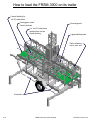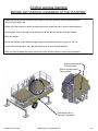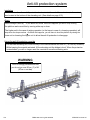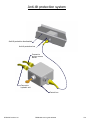
1
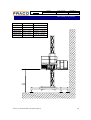
User's Guide
All you need to know about
the FRACO hydraulic
elevating platform
FRSM-3000
[English] FRSM-3000 06/2002 user's guide
All rights reserved. Any reproductions in part or in whole is strictly prohibited without the written consent of FRACO Products Ltd
Model
All
General
Date of issue
2006-12-19
Bulletin n°
U-T-0002-A
Mast climbing work platform
Mast bolt assembly procedure
Amendment to all the FRACO platforms User’s Guide
Please read carefully the present letter and insert it in all your Fraco User’s Guide:
All mast bolts must be installed head down and washer must be positioned on the nut side (see illustration).
Always tighten the nut. See user’s guide for specific bolt torque.
The most recent versions of our user’s guide are available on our Web site (www.fraco.com). Please refer
to them for assembly procedures with regards to changes above.
For more information, contact our Technical Department:
Julie Rainville
Technical Service Director
Fraco Products
T: 800-267-0094 / 450-658-0094
F: 450-658-8905
2001© Les Produits FRACO Products ltée/Ltd.
1
Model
All
Information
Date of issue
2006-12-06
Bulletin n°
U-T-0003-A
Mast climbing work platform
High priority warning: Height of the first and second wall tie
Amendment to all the FRACO platforms User’s Guide
Please read carefully the present letter and insert it in all your Fraco User’s Guide:
Fraco is changing the anchoring procedure for all types of platforms when using ground base. The most
recent versions of our user’s guide are available on our Web site (www.fraco.com). Please refer to them
for installation procedures with regards to changes below.
The two first ties must be at 10 and 20 feet ( 3m and 6 m) or at the two first accessible structural levels on
the building (max 20’) ( max 6 m ).
This new procedure is to upgrade the safety of our platform during the operation of installation and
dismantling.
The platform must be secured by lifting equipment while installing or dismantling the two first ties. Once
the second tie is in place, the installation continues by the usual procedure; reduce load platform (1/2 load)
except the ACT-4 and the anchoring sequence typical for the type of platform in use as shown below:
FRSM-1500, FRSM-3000, FRSM-8000 :
20 feet ( 6 m )
ACT-8 et FRSM-20 K :
30 feet ( 9 m )
ACT-4 :
40 feet ( 12 m )
For more information, contact our Technical Department:
Julie Rainville
Technical Service Director
Fraco Products
T: 800-267-0094 / 450-658-0094
F: 450-658-8905
2001© Les Produits FRACO Products ltée/Ltd.
1
Technical
Model
All
Date of issue
2007-01-16
Bulletin n°
B-T-0004-A
Mast climbing work platform
New specifications for use of free-standing bases for 20k, FRSM-8000,
FRSM-3000, FRSM-1500, ACT-4 and ACT-8
Amendment to FRACO platforms User’s Guides for models indicated above
Please read the following carefully and insert it in your Fraco User’s Guides:
Here are the new specifications for use of free-standing bases for 20K, ACT-4 and
ACT-8, FRSM-3000, FRSH-1500.
-
The outriggers of the deck must not be extended longer than the outriggers
of the base (maximum 3 planks, +/- 30’’[76 cm]). See attached drawing.
Do not extend the top deck outriggers if the bottom ones are already
extended.
The maximum wind speed for use and installation is 22 mph (35 km/h).
Use of portable crane, monorail, hard roof or weather enclosure is forbidden
without adding ties.
The outriggers of the base (back) must be fully open.
Here are the new specifications for usage of free-standing bases for FRSM-8000.
-
The outriggers of the deck must not be extended longer than the outriggers
of the base (maximum 5 planks, +/- 60’’[152 cm]). See attached drawing.
Do not extend the top deck outriggers if the bottom ones are already
extended.
The maximum wind speed for use and installation is 22 mph (35 km/h)
Use of portable crane, monorail, hard roof or weather enclosure is forbidden
without adding ties.
The outriggers of the base (back) must be fully open.
For further information or any question please contact:
Jean-François Laurin T.P. or Jean-Sébastien Lasnier T.P.
Telephone : 450-658-0094
Toll Free : 800-267-0094
Fax : 450-658-8905
2001© Les Produits FRACO Products ltée/Ltd.
1/2
Model
All
Technical
Date of issue
2007-01-16
Bulletin n°
B-T-0004-A
Mast climbing work platform
Type
ACT-4
ACT-8
20K
FRSM-8000
FRSM-3000
FRSM-1500
Max. height
60’0” (18.3m)
45’0” (13.7m)
45’0” (13.7m)
42’0” (12.8m)
35’0” (10.7m)
35’0” (10.7m)
Capacity
4 000 lbs (1 815 kg)
8 000 lbs (3 630 kg)
10 000 lbs (4 535 kg)
8 000 lbs (3 630 kg)
3 000 lbs (1 360 kg)
1 500 lbs (680 kg)
FRACO
FRACO
FRACO
FRACO
Max.
height
2001© Les Produits FRACO Products ltée/Ltd.
2/2
Les Produits Fraco Ltée
91, Chemin des Patriotes, St-Mathias-Sur-Richelieu, Quebec, Canada J3L 6B6
Tel: (450) 658-0094 Fax: (450) 658-8905 CDA: 1-800-267-0094 USA: 1-888-372-2648
www.fraco.com email: [email protected]
DECLARATION
OF CONFORMITY
N° 00770077/5162/760/01/10/1301
Type:
Device for the lifting of persons or persons and objects, involving a risk of falling from vertical height of
more than 3 meters. Mast climbing work platform, single or twin mast.
Brand: FRACO Model: FRSM-3000
Serial Number:
Technical details:
In single mast:
¾ Rated load / Number of persons:
¾ Working height:
¾ Length / Width of platform:
¾ Reduced load:
In twin masts:
¾ Rated load / Number of persons:
¾ Working height:
¾ Length / Width of platform:
¾ Reduced load:
1 720 kg / 3 persons
11,3m (Freestanding) – 101m (with anchorages)
11,2m / 3,0m
906 kg/3 persons at max length (10,8m)
3,560 kg / 7 persons
11,3m (Freestanding) – 101m (with anchorages)
23,9 m / 3,4 m
1 816 kg/7 persons at max length (25,9m)
This model complies with all relevant provisions of the machinery directive 2006/42/CE (95/16/CE modified) on the approximation
of the laws of the Member States. This model complies with the essential safety and health requirements applicable to it. This
declaration concern exclusively the machines in the condition in which they entered the market, and exclude the components that
have been added and/or the operations carried out afterward by the final user.
Notified Organism
APAVE Parisienne
No d’identification : 0077
13 à 17, rue Salneuve – 75854 PARIS CEDEX 17
Technical file
SARL Fraco
420 rue des Érables – F-60710 CHEVRIÈRES
FRANCE
______________________________
La Vice-présidente
Les Produits FRACO Ltée
St-Mathias-Sur-Richelieu
29 décembre 2009
Claudette L'Heureux
TRANSLATED FROM ORIGINAL NOTICE
Congratulations!
You are about to use the excellent
FRACO hydraulic elevating work platform system!
Unlike any other platform system on the market today,
FRACO provides you with the ultimate in SAFETY, STABILITY and FLEXIBILITY
while reducing your labour costs by up to 36%.
Due to the advanced technology of FRACO Products,
you can be assured of the OPTIMUM QUALITY in all our products.
FRACO is ISO 9001 registered
The instruction manual and safety rules presented on the following pages will safely guide you
through all the possibilities of this system. The platform cannot be sold or rented without this user's
guide.
FRACO Products Ltd reserves the right to modify the platform or its manual without notice, and
will not assume any responsibility for any prejudices that may occur.
This FRACO system meets ANSI and OSHA requirements.
MANUFACTURER
FRACO Products Ltd
91 Chemin des Patriotes
St-Mathias-sur-Richelieu
Québec, Canada, J3L 6A1
www.fraco.com
[email protected]
DISTRIBUTOR
Certified APAVE
(450) 658-0094
If you have any questions, do not hesitate in calling us at :
Canada: 1-800-267-0094
Montreal: (514) 990-7750
U.S.A.: 1-888-FRACO 4 U
1-888-372-2648
or fax us at: (450) 658-8905
©FRACO Products Ltd
FRSM-3000 user's guide 06/2002
I-1
Table of contents
Part I: All you need to know - general information
•
•
•
•
•
•
Congratulation!
Table of content
Warning
General view
Identification plate
Technical data
I-1
I-2
I-3
I-4
I-5
I-6
Part II: Installing the platform
•
•
•
•
•
•
•
•
•
•
•
•
•
•
•
Distance between 2 masts sections
Installing the FRACO platform
Installing the elevating unit (Trailer)
Installing the elevating unit (Ground base)
Extension
Bridge assembly
Bridge installation
Side bracket
Guardrail bracket
Flooring
Guardrail
Extensible guardrail & anti-skid plate
Outrigger
Plank tie
Plank-end guardrail
II-1
II-2
II-3
II-4
II-5
II-6
II-7
II-8
II-9
II-10
II-11
II-12
II-13
II-14
II-15
Part III: Options
•
•
•
•
Outrigger guardrail
Outrigger tie
Single mast locking system
Protection mesh
III-1
III-2
III-3
III-4
Part IV: Mast and anc hor installation
•
•
•
•
•
•
•
•
•
•
•
•
•
•
•
Installation of mast sections
Erection of a mast
End of mast section
Anchor positions
Anchor assembly
Minimal anchor opening
How to level the mast using the anchors
Anchor bolted to a angle iron
Anchor bolted to a structural “H” beam
Anchor for a concrete structural or beam
Horizontal anchor for concrete structure
Anchor welded to a angle iron
Anchor welded to a structural “H” beam
Anchoring box for concrete floor
Adjustable anchor for H-beam
IV-1
IV-2
IV-3
IV-4
IV-5
IV-6
IV-7
IV-8
IV-9
IV-10
IV-11
IV-12
IV-13
IV-14
IV-15
Part V: Operating the platform
•
•
•
•
•
•
•
•
Standard weight distribution (double mast)
Standard weight distribution (single mast)
How to raise the platform
How to lower the platform
Dismantling the mast, anchor and platform
Moving the platform
Maintenance
How to load the FRSM-3000 on it’s trailer
V-1
V-2
V-3
V-4
V-5
V-6
V-7
V-8
Part VI: Operation options on the FRACO system
•
•
•
I-2
Anchor access barriers
Anti-tilt protection system
Anti-tilt protection system
FRSM-3000 user's guide 06/2002
VI-1
VI-2
VI-3
©FRACO Products Ltd
WARNING!
SAFETY IS OUR PRIMARY CONCERN.
For this reason, never remove or alter any part in order to adapt the platform to fit a specific area of the
building.
USE ONLY GENUINE FRACO PARTS
PLEASE READ THE FOLLOWING INSTRUCTIONS CAREFULLY BEFORE INSTALLATION
FRACO (and/or its importer/representative) cannot be responsible for any property damage, severe
injury or death that may result from failure to comply with the following safety recommendations,
local rules and regulations.
Before operating this FRACO System, the following safety rules must be read and fully understood:
1- Mark out, with beacons or barricade tape, and forbid the access around the base and the platform. This should be done
according to the local rules.
2- If using a gasoline engine, do not work in an explosive environnent such as refineries, etc.
3- The operator should be familiar with the user's guide and understand all the functions of the platform.
4- Never assume anything. If you have any questions concerning the operation of the FRACO, STOP! Refer to the proper
user's guide. If you are still unsure, do not continue and call FRACO immediately.
5- In order to use, install or dismantle the system, a minimum of 2 people should be on the platform at all times,
in case of a breakdown or rescue.
6- The maximum working height is 11,58 m (38 ft) in freestanding mode when in use and 3 m (12 ft) otherwise.
7- If you need to go higher than 11,58 m (38 ft), you should use anchors. In that case, refer to the user's guide.
8- Always use anchors when you are not using the freestanding base.
9- This platform should be maintained periodically. Refer to the user's guide.
10- In case of an electrical storm, LEAVE the platform.
11- For personal safety, when the wind exceeds 50 km/h (30 mph) do not use, install or dismantle the platform. Make sure
that the platform is lowered to the minimum.
12- Note the place where your fire extinguisher is located, and make sure that a certified person verifies it periodically.
13- It is the operator's responsibility to ensure that the load and the number of people allowed on the platform
is complied with. (Refer to the standard load distribution chart).
14- This platform should never be specifically used as an elevator.
Always wear your safety harness when installing and dismantling the mast sections, the anchors and
when manipulating the planks when passing the anchors.
Safety harnesses that meet the local safety code must be available at all times for each person on the
platform. A safety line, in compliance with the codes and of sufficient length for the working height of the
platform must be available at all times on the platform for emergency use only..
Before raising or lowering the FRACO make sure:
1- That the base is properly secured in position and leveled (see the tolerances permitted in the user's guide).
2- That all guardrails are in place.
3- That a visual inspection above and below the platform is carried out, before each vertical movement, to
ensure no protrusions will impede or inhibit the proper movement of the FRACO.
4- To verify proper clearance for the walk boards (planks).
Honda Gas Engine
5- Not to exceed the freestanding working height 11,58 m
Model: GX270-QX B6
(38 ft) from the ground.
Vibration: 4.0 G Noise level: 70 dB
6- That the platform has not exceeded the height of the last anchor.
Operating speed: 3 600 RPM
7- That the worker removing the boards to pass the anchors is
properly harnessed.
8- That everyone on board is alerted.
9- That the safety material is in the proper place and within reach of the operators.
©FRACO Products Ltd
FRSM-3000 user's guide 06/2002
I-3
General view
16
1
2
3
15
14
4
13
5
12
6
7
Item
1
2
3
4
5
6
7
8
9
10
11
12
13
14
15
16
I-4
Parts List
Description
Elevating unit
Mast section
Anchor
Plank-end guardrail
Guardrail bracket
Extension
Side bracket
Trailer
Stabilizer
Jack
Wooden jack pad
Stair access
Engine support
Outrigger
Access door
Guardrail
8
9
10
11
FRSM-3000 user's guide 06/2002
©FRACO Products Ltd
Identification plate
This plate is found on the climbing frame
and should be visible at all times
91, CHEMIN DES PATRIOTES, ST-MATHIAS-SUR-RICHEULIEU,
QUÉBEC,CANADA,J3L 6A1
NO. SÉRIE
SERIAL NO.
NO. SERIE
XX
XX
XXXX
Patent pending no.: 9,114,923
MODÈLE
MODEL
MODELO
FRSM-3000
Vitesse de déplacement vertical
vertical travel speed
velocidad de elevation
}
0-0,05 m/s
0-0,20 pi/s
0-0,05 m/s
MADE IN
FABRIQUÉ AU
HECHO EN
Serial number
XX
XX
XXXX
Model number
Platform number
Year of fabrication
©FRACO Products Ltd
FRSM-3000 user's guide 06/2002
I-5
Technical data
Model number
FRR -5000 (Trailer)
Weight on the hitch
156 lbs
Tire dimensions
70,76 kg
ST 225 / 75 R 15
Overall length
18 ft 6 in
5,64 m
Overall width
6 ft 1 in
1,85 m
Total weight
2 055 lbs
934 kg
Total weight + FRSM-3000
3 885 lbs
1 766 kg
Ground base (dimensions / weight)
1,50 m x 0,97 m / 130 kg
59 in x 38 in / 285 lbs
Model number
FRSM-3000
Maximum length of platform (single mast)
28 ft 8 in
8,75 m
Maximum length of platform (double mast)
78 ft
23,77 m
Lower working area width
1 ft to 5 ft
0,3 m to 1,52 m
Standard : 4 ft 10 in
Standard : 1,47 m
Maximum : 7 ft 2 in
Maximum : 2,18 m
Lifting speed
12 ft / minute
3,6 m / minute
Maximum height of the mast (with anchors)
330 ft
101 m
38 ft
11,58 m
32 in
82 cm
Upper walking and loading area
Maximum height of the mast
(without anchors)
Minimum ground clearance
HONDA engine
9 HP
Mast section (dimensions / weight)
16 in x 16 in x 5 ft / 133 lbs
Elevating unit (dimensions / weight)
40 cm x 40 cm x 1,52 m / 60.5 kg
28 in x 28 in x 60 in / 1 830 lbs
71 cm x 71 cm x 1,52 m / 831 kg
30 in x 26 in x 40 in / 141 lbs
76 cm x 66 cm x 1 m / 64 kg
30 in x 26 in x 80 in / 243 lbs
76 cm x 66 cm x 2 m / 110 kg
Bridge section (dimensions / weight)
30 in x 27 in x 10 ft / 472 lbs
76 cm x 67 cm x 3 m / 214 kg
Central bridge section (dimensions / weight)
30 in x 27 in x 10 ft / 395 lbs
76 cm x 67 cm x 3 m / 200 kg
Extension section (dimensions / weight)
I-6
FRSM-3000 user's guide 06/2002
©FRACO Products Ltd
Part II
Installing the platform
Distance between 2 mast sections
Total length
Distance between masts
Including two 1 m (3'4") extentions MANDATORY
Maximum length in double mast configuration: 23,78 m (78')
Minimum length in double mast configuration: 11,58 m (38')
Maximum length in single mast configuration: 8,74 m (28'8")
Minimum length in single mast configuration: 2,64 m (8'8")
Distance between the masts in a double mast configuration*
Between masts
Between masts
minimum
standard
6 m (20')
8,97 m (29'5'')
9,09 m (29'10'')
9 m (30')
12,01 m (39'5'')
12,14 m (39'10'')
12 m (40')
15,06 m (49'5'')
15,19 m (49'10'')
*The bridge arms must be extended from 5 cm (2'') to 15 cm (6'').
Bridge type
Between masts
maximum
9,20 m (30'2'')
12,24 m (40'2'')
15,29 m (50'2'')
*Including two 1 m (3'4") extentions MANDATORY.
©FRACO Products Ltd
FRSM-3000 user's guide 06/2002
II-1
Installing the FRACO platform
Verify the ground weight bearing capacity and make sure that it can support the base and the platform:
Mast height
0 to 30,5 m (100’)
30,5 to 61 m (100’ to 200’)
61 m to 101 (200’ to 330’)
Ground capacity
34 kN/sq. m (700 lbf/sq. foot)
44 kN/sq. m (900 lbf/sq. foot)
48 kN/sq. m (1 000 lbf/sq. foot)
When using the standard ground base: (see page II- 4)
1- Start by levelling the ground with a maximum of 10 cm (4'' )of material (crushed stone is
recommended).
2- Measure the exact distance "L" between the base and the wall, taking into account all
obstacles that the platform will have to go around. Also take into account the
mast-to-mast distance when using a double mast configuration (see page II-1).
Installation type
Standard
Distance "L"
0,76 m (30'') for 2 planks
1,02 m (40'')
1,27 m (50'')
1,52 m (60'') for 5 planks
Other possibilities
Maximum
3- Install the FRACO system (elevating unit and base) perfectly perpendicular to the wall at
the appropriate ''L'' distance.
4- Make sure that the mast is perfectly vertical and that the base is level and stable.
When using the trailer: (see page II-3)
1- Measure the exact distance "L" between the base and the wall, taking into account all
obstacles that the platform will have to go around. (see page II- 4) Also take into account
the mast-to-mast distance when using a double mast configuration (see page II- 1).
Installation type
Standard
Maximum
Distance "L"
Distance "D"
0,86 m (34'')
1,62 m (64'')
25 cm (10'')
MANDATORY
**Always install wooden jack pads under stabilizer jack plates**
2- Install the FRACO system (elevating unit and trailer) perfectly perpendicular to the wall
with the appropriate "L" and "D'' distances.
3- Extend the stabilizers of the trailer : rear ones 94 cm (37'') and thef ront ones at distance ''D''.
Lower the jacks onto the jack pads (see instructions on the stabilizers).
4- Level the mast with a bubble level. After levelling, the wheels of the trailer must turn freely
and should not touch the ground.
5- Make sure that the mast is perfectly vertical and that the base is level and stable.
II-2
FRSM-3000 user's guide 06/2002
©FRACO Products Ltd
Installing the elevating unit
Trailer
5,77 m (18'11")
3,80 m (12'6'')
94 cm (37") min
2,97 m (9'9")
"D"
"L"
Wall
If you have to go over the freestanding
height of 11,58 m (38') and use anchors,
close the 4 stabilizers to the minimum
The maximum height for a freestanding
base with anchors is 30,5 m (100').
Elevating unit
Installation
1-Deploy the rear stabilizers
to 0,94m (37").
Jack handle
Trailer
2-Deploy the front stabilizers
to 25 cm (10").
3-Place the 4 wooden jack pads
under the stabilizers.
4-Install the elevating unit
on its trailer perfectly
perpenticular to the wall
using the appropriate "L" and
''D'' distances. (page II-2)
5-Level the base using the jack
handle and the stabilizers.
©FRACO Products Ltd
Wooden jack pad
Stabilizer
FRSM-3000 user's guide 06/2002
II-3
Installing the elevating unit
Ground base
Installation
1-Make a bed of crushed stone exceeding
the base by a minimum of 25 mm (1").
2-Install the elevating unit perfectly
perpendicular to the wall.
3-Make sure that the unit mast is plumb.
1,5m (5')
mast section
Elevating unit
"L"
Ground base
Levelled ground
Existing ground
II-4
FRSM-3000 user's guide 06/2002
©FRACO Products Ltd
Extension
Installation
1-Install the extension on the hooks of the elevating unit or
on the hooks of another extension.
2-Bolt the extension to the elevating unit or to another
extension using two Ø16 mm X 50 mm (Ø5/8" x 2'')
bolts.
IMPORTANT:
-Make sure you do not have more than 3 m (10') of difference
between the extensions during the installation.
-When you are done, there can be a maximum difference of
1 m (3'4") between the extensions.
-The maximum extension length is 4 m (13'4").
Elevating unit
DETAIL-A
A325 Ø16 mm x 50 mm
(Ø5/8" X 2'') bolt
2 m (6'8") extension
15010029
1 m (3'4") extension
15010018
A
©FRACO Products Ltd
FRSM-3000 user's guide 06/2002
II-5
Bridge assembly
Bridge
3 m (10') section
3 m (10') central section
weight
406 kg
(900 lbs)
6m
(20')
2
0
9m
(30')
2
1
12 m
(40')
2
2
580 kg
(1280lbs)
752 kg
(1650 lbs)
Ø19 mm X 139 mm
Ø3/4" X 5 1/2" bolts
Bridge arms
DETAIL-A
3 m (10') central bridge section
A
3 m (10') bridge section
1-Assemble the bridge to the desired length using the "bridge assembly" chart.
THE MAXIMUM LENGTH OF A BRIDGE IS 12 m (40').
2-Bolt all 3 m (10') sections together using six Ø19 mm x 139 mm (Ø3/4" x 5 1/2'') bolts.
II-6
FRSM-3000 user's guide 06/2002
©FRACO Products Ltd
Bridge installation
Installation
1-Install a 1 m (3'4'') extension on each side of the bridge. (see page II-6)
2-Bolt the 1 m (3'4") extension to the elevating unit with 2 bolts. (see page II-6)
3-Insert the bridge arms in the hooks of the 1 m (3'4'') extension section.
4-Install the locks to secure the bridge arms and lock them with a safety pin.
Bridge arm
IMPORTANT
Always install a 1 m (3'4'') extension
when using a bridge
Lock
DETAIL-A
Elevating unit
1 m (3'4'') extension
15010018
Bridge
©FRACO Products Ltd
A
FRSM-3000 user's guide 06/2002
II-7
Side bracket
Ø16 mm X 100 mm
(Ø5/8" X 4") pin
Installation
Side bracket adapter
1-Insert the side bracket in its
adapter.
2-Lock the side bracket with a
Ø16 mm X 100 mm (Ø5/8" X 4")
pin and a cotter pin.
Side bracket adapter
DETAIL-A
Side bracket
A
II-8
FRSM-3000 user's guide 06/2002
©FRACO Products Ltd
Guardrail bracket
1-Install the guardrail bracket in the hooks at the end of the
last extension section.
2-Secure the guardrail bracket and the side bracket with their
Ø16 mm X 150 mm (Ø5/8" X 6") pins and 2 cotter pins.
Guardrail bracket
Left: 20490308
Right: 20490285
DETAIL-A
©FRACO Products Ltd
A
Ø16 mm X 150 mm
(Ø5/8" X 6") pin
FRSM-3000 user's guide 06/2002
II-9
Flooring
U-lock
2549088
Wood decking
Installation
1-Install the flooring on the side brackets in
order to cover the entire circulation zone.
2-Lock the flooring with a U-lock and a
safety pin.
Safety pin
DETAIL-A
1 m (3'4'') flooring
16030055
2 m (6'8'') flooring
16030066
A
Flooring used regarding the lenght of platform
Fiber flooring
Platform lenght
1 m (3’4’’) extension
2 m (6’8’’) extension
3 m (10’) extension
4 m (13’4’’) extension
6,10 m (20’) bridge
9,14 m (30’) bridge
12,19 m (40’) bridge
II-10
1 m x 0,71 m
(3’4’’ x 28’’)
1
1
2
1
FRSM-3000 user's guide 06/2002
2 m x 0,71 m
(6’8’’ x 28’’)
1
1
1
3
4
6
©FRACO Products Ltd
Guardrail
Installation
1-Insert the guardrail in the side bracket and the guardrail bracket.
2-Insert the two stair guardrails CE on the stair in their adapters.
3-Install the guardrails wherever there might be a risk of falling.
1 m (3'4") guardrail
17490023
60 cm (23") guardrail
17490012
Adapters
Stair guardrail CE
17490102
©FRACO Products Ltd
FRSM-3000 user's guide 06/2002
II-11
Extensible guardrail & anti-skid plate
Anti-skid steel plate
70 cm (28'') : 20490319
100 cm (40'') : 20490320
Installation
Extensible guardrail
Extensible guardrail
17490034
1-Install the extensible guardrail on the
existing guardrails where there are gaps.
2-Lock the extensible guardrail with safety pins.
3-The safety pins must be re-installed each
time the extensible guardrail is moved.
Anti-skid plate
1-Install the anti-skid plate on the
gaps created by the bridge arms.
2-Secure them with screws or nails on one side
only, to allow movement of the bridge arms.
DETAIL-A
Safety pins
A
II-12
FRSM-3000 user's guide 06/2002
©FRACO Products Ltd
Outrigger
Installation
1-Make sure that a Ø9 mm (Ø3/8") bolt is in place before installing
the outriggers.
2-Install the outriggers in the lower or upper adapters. (DETAIL-A)
3-Install the outriggers so that there is no more than one free
outrigger adapter between each outrigger. (DETAIL-B).
4-Install a pin with washer in each outrigger and secure
with a cotter pin.
5-The outriggers cannot be deployed more than 1,52 m (5').
Pin with washer
25490088
DETAIL-A
Ø9 mm bolt
(Ø3/8")
Outrigger adapter
DETAIL-B
Cotter pin
DETAIL-C
B
C
Lower adapters
Outrigger
19010034
©FRACO Products Ltd
Upper adapters
FRSM-3000 user's guide 06/2002
II-13
Plank tie
Installation
1-Install the plank ties so that they hold the outriggers and the planks together.
2-Nail or screw the plank ties to the planks so that they do not move.
Warning
Never place any
Use only #1 category spruce or equivalent* having
dimensions of 50 mm X 250 mm (2" x 10") 350 kg/m²
(71.5 lbs/pi ²) for a span less than 1,80 m (6').
load on the planks
at any time
The planks must be 15 cm (6" ) from the
wall and 1,5 cm (1/2") from the extensions.
Nails/screw
Plank tie
DETAIL -A
1,5 cm
(1/2")
A
*Use only planks approved by the local authorities
II-14
FRSM-3000 user's guide 06/2002
©FRACO Products Ltd
Plank-end guardrail
Installation
1-Install the plank-end guardrails
at the end of the work zone planks.
2-Secure them with screws or nails.
3-Place the plank-end guardrails
wherever there might be a risk of
falling.
Plank-end guardrail
17490045
DETAIL-A
A
©FRACO Products Ltd
FRSM-3000 user's guide 06/2002
II-15
Part III
Options/Miscellaneous
Outrigger guardrail
Pin with washer
1-Install the outrigger guardrails at
all the places required to prevent
any risk of falling.
2-Lock the outrigger guardrails with
their pins with washer and cotter pins.
3-Insert 50mm X 100mm (2" X 4")
planks in the outrigger guardrails and
secure them with nails or screws.
Outrigger guardrail
17490067
Cotter pin
DETAIL-A
WARNING
Never place any load
on the planks at any time
A
©FRACO Products Ltd
FRSM-3000 user's guide 06/2002
III-1
Outrigger tie
Always use 2 outrigger ties for each additional outrigger
Installation
1-Install the outrigger ties on the previously installed outriggers.
2-Secure the ties with Ø19 mm x 100 mm (Ø5/8'' x 4'') pins
and lock them with cotter pins.
3-Install pins with washers on the new outriggers. (page II-13)
4-Place planks on the new work area.
WARNING
Never place any load on
the planks at any time
Installation only permitted
with 1m, 2m & 3 m
(3'4 ", 6'8" & 10') extensions
Always use 2 outrigger ties
for each additional outrigger
Ø19 mm x 100 mm
(Ø5/8'' x 4'') pin
DETAIL-A
Outrigger tie
20490038
A
III-2
FRSM -3000 user's guide 06/2002
©FRACO Products Ltd
Single mast locking system
Always install a single mast locking system when in a single mast configuration
Installation
1-Insert an outrigger lock on the outrigger furthest from the mast. (DETAIL-A)
2-Install the wheel at the end of the outriggers with outrigger locks.
3-Lock the wheel with a pin with washer and a cotter pin. (DETAIL-B)
4-Adjust the distance between the wheel and the wall to 3 cm (1 1/8").
5-Tighten the bolts on the outrigger locks.
Pin with washer
Wheel
20490263
Outrigger lock
20490072
DETAIL-A
DETAIL-B
Cotter pin
A
B
©FRACO Products Ltd
FRSM-3000 user's guide 06/2002
III-3
Protection mesh
Installation
1-Insert the protection mesh on top of the
elevating unit to extend the protection.
Protection mesh
20490397
III-4
FRSM-3000 user's guide 06/2002
©FRACO Products Ltd
Part IV
Mast and anchor installation
Installation of mast sections
Installation:
1-Divide the mast sections equally on each side of the elevating unit.
2-Flip the panels on the elevating unit and manually install the mast sections.
3-Follow the instructions on page IV-2.
WARNING
When carrying masts over the anchors, the total permissible load
is 682 kg (1 500 lbs) uniformly distributed and including workers
2 workers needed
Elevating unit
side panel
End of mast detector
A
Detail-A on the next page (IV-2)
©FRACO Products Ltd
FRSM-3000 user's guide 06/2002
IV-1
Erection of a mast
Installation
1-Join the male and female sections.
2-Bolt them together with 4 bolts.
Important:
1-Do not add more than 6 mast sections (7 mast sections
total) to the FRACO system. The maximum freestanding
height is 11,58 m (38').
2-Check to make sure that the claws are on the same side
on each mast section
.
Ø16 mm X 114 mm
(Ø5/8" X 4 1/2") bolt
A
DETAIL-A
torque = 206 newton - meter
(152 foot - pound)
Do not exceed the following vertical tolerances
- 1,25 cm (1/2") for a 3m (10') mast.
- 2 cm (3/4") for a 6m (20') mast.
- 2,5 cm (1") for the maximum mast height.
IV-2
FRSM-3000 user's guide 06/2002
©FRACO Products Ltd
End of mast section
Installation
1-Once the last mast section is installed, bolt the end of mast section on top using four
Ø16 mm X 114 mm (Ø5/8" X 4 1/2'') bolts and four I.D. 16 mm (5/8") washers.
Ø16 mm X 114 mm
(Ø5/8" X 4" 1/2) bolt
End of mast section
©FRACO Products Ltd
FRSM-3000 user's guide 06/2002
IV-3
Anchor positions
IMPORTANT
1-With a ground base, the first anchor
must be installed before:
Elevating the platform
Placing any load on the platform
2-Load on the platform only the mast sections
required to reach the next anchor.
3-In a work situation, the platform must
never go above the last anchor.*
FIRST ANCHOR:
6 m (20') maximum from the ground
OTHER ANCHORS:
Maximum 6 m (20') between
the anchors
*-TO INSTALL THE ANCHORS ONLY, It is
permitted to exceed the last anchor by 6 m
(20') with a load less than 682 kg (1 500 lbs),
two men and tools when the first anchor
is installed.
IV-4
FRSM-3000 user's guide 06/2002
©FRACO Products Ltd
Anchor assembly
Ø14 mm X 75 mm pin
(Ø5/8" X 3")
Turnbuckle with hand
23020018
Wall tie
21490040
Wall tie
21490039
Turnbuckle with nut
23050011
Turnbuckle hand
23030019
Maximum
Deployment limit
Cotter pin
Central tube
22010050
Wall tie with blabe
21490084
Ø12mm X 100mm
(Ø1/2" X 4") pin
Turnbuckle extention
23040021
Ø75mm X 100mm
(Ø3/4" X 4") pin
-The length of the central tube may vary depending on the needs.
-The turnbuckle may be extended with turnbuckle extention.
©FRACO Products Ltd
FRSM-3000 user's guide 06/2002
IV-5
Minimum anchor opening relative
to the distance from the wall
Central tube
length
H (min)
0,61 m
(2')
0,66 m (2'4")
0,91 m
(3')
0,97 m (3'2")
1,22m
(4')
1,27 m (4'2")
1,52m
(5')
1,58 m (5'2")
1,83 m
(6')
1,88 m (6'2")
H (max)
0,99 m (3'3")
1,30 m (4'3")
1,60 m (5'3")
1,91 m (6'3")
2,21 m (7'3")
W (min) 30°
W (std) 45°
0,60 m (1'3'')
0,76 m (2'6")
0,71 m (2'4")
1,09 m (3'7")
1,07 m (3'6")
1,45 m (4'9")
1,42 m (4'8")
1,80 m (5'11'')
1,78 m (5'10")
2,16 m (8'1")
0,64 m (2'1")
1,30 m (5'3")
1,25 m (4'1")
1,91 m (6'3")
1,85 m (6'1")
2,51 m (8'3")
2,46 m (8'1")
3,12 m (10'3")
3,07 m (10'1")
3,73 m (12'3")
W
30° to 45°
WALL
H
IV-6
FRSM-3000 user's guide 06/2002
©FRACO Products Ltd
How to level the mast using the anchors
Warning
Never exceed the following vertical tolerances
- 1,25 cm (1/2") for a 3 m(10') mast.
- 2 cm ( 3/4") for a 6 m (20") mast.
- 2,5 cm (1") for the maximum mast height.
TYPE #2
TYPE #1A
TYPE #3
TYPE #1B
TYPE #1: Adjusting the distance on both sides between the platform and the wall.
TYPE #2: Levelling the mast from left to right.
TYPE #3: Levelling the mast from front to back.
TYPE #1
Situation 1A<1B 1A>1B
A
B
C
D
E
F
TYPE #2
Left
TYPE #3
Right
Front
Back
Situations
A- Move the central tube to the left.
B- Move the central tube to the right.
C- Shorten the left turnbuckle and extend
the right one.
D- Shorten the right turnbuckle and extend
the left one.
E- Shorten both turnbuckles and the central tube.
F- Extend both turnbuckles and the central tube.
©FRACO Products Ltd
FRSM-3000 user's guide 06/2002
IV-7
Anchor bolted to an angle iron
WARNING : Before making any modification to a
structural component, have an engineer approve it.
Installation
1-Install the wall tie and the central tube.
2-Locate the place to drill the holes for the turnbuckles using page IV-5.
3-Level the mast using the turnbuckles. (adjustment TYPE #2 & #3)
4-Drill a hole in the angle iron for the central tube. (adjustment TYPE #1)
5-Make sure that all the pins are in place and are secured by cotter pins.
IV-8
FRSM-3000 user's guide 06/2002
©FRACO Products Ltd
Anchor bolted to a structural H-beam
WARNING : Before making any modification to a
structural component, have an engineer approve it.
Installation
1-Install the wall tie and the central tube.
2-Locate the place to drill the holes for the turnbuckles using page IV-5.
3-Level the mast using the turnbuckles. (adjustment TYPE #2 & #3)
4-Drill a hole in the structural H-beam for the central tube. (adjustment TYPE #1)
5-Make sure that all the pins are in place and are secured by cotter pins.
©FRACO Products Ltd
FRSM-3000 user`s guide 06/2002
IV-9
Anchor for a concrete structure or beam
Ø16 mm x 127 mm (Ø5/8" x 5'')
Wedge bolt or approved equivalent
Concrete anchor
24010029
Ø16 mm x 127 mm (Ø5/8" x 5'')
Wedge bolt or approved equivalent
Installation:
1-Install the wall tie and the central tube.
2-Locate the place to install the concrete anchors for the turnbuckles using page IV-5.
3-Level the mast using the turnbuckles. (adjustment TYPE #2 & #3)
4-Install the concrete anchor for the central tube. (adjustment TYPE #1)
5-Make sure that all the pins are in place and are secured by cotter pins.
The concrete must have a resistance of 30 MPa (4 000 psi) minimum.
Ø16 mm x 127 mm (Ø5/8" x 5'') Wedge bolt
IV-10
FRSM-3000 user's guide 06/2002
©FRACO Products Ltd
Horizontal anchor for concrete structure
Ø16 mm x 127 mm (Ø5/8" x 5'')
Wedge bolt or approved equivalent
Ø16 mm x 127 mm (Ø5/8" x 5'')
Wedge bolt or approved equivalent
Installation:
1-Install the wall tie and the central tube.
2-Locate the place to install the concrete anchors for the turnbuckles using page IV-5.
3-Level the mast using the turnbuckles. (adjustment TYPE #2 & #3)
4-Install the horizontal anchor for the central tube. (adjustment TYPE #1)
5-Make sure that all the pins are in place and are secured by cotter pins.
The concrete must have a resistance of 30 MPa (4 000 psi) minimum.
Horizontal concrete anchor
24010030
©FRACO Products Ltd
FRSM-3000 user's guide 06/2002
IV-11
Anchor welded to an angle iron
WARNING : Before making any modification to a
structural component, have an engineer approve it.
127 mm (5") min.
6 mm (1/4")
weld bead
Installation
1-Install the wall tie and the central tube.
2-Locate the place to weld the plates for the turnbuckles using page IV-5.
3-Level the mast using the turnbuckles. (adjustment TYPE #2 & #3)
4-Weld the plate for the central tube on the angle iron. (adjustment TYPE #1)
5-Make sure that all the pins are in place and are secured by cotter pins.
IV-12
FRSM-3000 user's guide 06/2002
©FRACO Products Ltd
Anchor welded to a structural H-beam
WARNING : Before making any modification to a
structural component, have an engineer approve it.
127 mm(5") min.
6 mm (1/4")
weld bead
Installation
1-Install the wall tie and the central tube.
2-Locate the place to weld the plates for the turnbuckles using page IV-5.
3-Level the mast using the turnbuckles (adjustment TYPE #2 & #3)
4-Weld the plate on the structural H-beam for the central tube (adjustment TYPE #1)
5-Make sure that all the pins are in place and are secured by cotter pins.
©FRACO Products Ltd
FRSM-3000 user's guide 06/2002
IV-13
Anchoring box for concrete floor
Installation:
1-Install the concrete anchoring box with 3 Wedge bolts at each plate.*
2-Install the central tube in the holes already drilled on the angle iron.
3-Install the turnbuckles in the holes already drilled on the angle iron.
4-Make sure that all the pins are in place.
5-Lock the pins with cotter pins.
*-You do not have to use the inner Quick bolt on each plate.
Ø16 mm X 127 mm
(Ø5/8" X 5") Wedge bolt
or approved equivalent
IV-14
FRSM-3000 user's guide 06/2002
©FRACO Products Ltd
Adjustable anchor for H-beam
WARNING: The strength of the H-beam
must be tested by an engineer
H-beam adjustable anchor
24490021
Installation:
1-Install the wall tie and the central tube.
2-Install the adjustable anchors for the turnbuckles using page IV-5.
3-Level the mast using the turnbuckles (adjustment TYPE #2 & #3)
4-Install the adjustable anchor for the central tube (adjustment TYPE #1)
5-Make sure that all the pins are in place and are secured by cotter pins.
©FRACO Products Ltd
FRSM-3000 user's guide 06/2002
IV-15
Part V
Operating the platform
Standard weight distribution
Single mast configuration
Working zone - 5 workers
Traveling zone - 1 worker
Total permissible load is 1 364 kg (3 000 lbs) including workers
The load must be uniformly distributed on the platform.
The loading zone is located with in 2 m (7') on both sides of the elevating unit.
IMPORTANT
Never place any load on the work
zone or the traveling zone
©FRACO Products Ltd
FRSM-3000 user's guide 06/2002
V-1
Standard weight distribution
Single mast configuration
Working zone - 5 workers
Traveling zone - 1 worker
Total permissible load is 909 kg (2 000 lbs) including workers
The load must be uniformly distributed on the platform.
The loading zone is located with in 2 m (7') on both sides of the elevating unit.
IMPORTANT
Never place any load on the work
zone or the traveling zone
V-2
FRSM-3000 user`s guide 06/2002
©FRACO Products Ltd
©FRACO Products Ltd
IMPORTANT
Never place any load on the work
zone or the traveling zone
Working zone - 5 workers
The load must be uniformly distributed on the platform.
The loading zone is located with in 2 m (7') on both sides of the elevating unit.
Standard weight distribution
FRSM-3000 user's guide 06/2002
Total permissible load is 2 727 kg (6 000 lbs) including workers.
Double mast configuration
Traveling zone - 2 workers
V-3
V-4
IMPORTANT
Never place any load on the work
zone or the traveling zone
Working zone - 5 workers
Double mast configuration
Manuel d'utilisation FRSM-3000 09/2002
©Les Produits FRACO Ltée
Total permissible load is 2 273 kg (5 000 lbs) including workers.
The load must be uniformly distributed on the platform.
The loading zone is located with in 2 m (7') on both sides of the elevating unit.
Standard weight distribution
Traveling zone - 2 workers
How to raise the platform
Precautions to take before making any vertical movement with the patform
1-Tie yourself to an anchoring point or to the elevating unit and remove the
planks that might interfere with the anchors.
2-Check to make sure that the platform trajectory is clear of all obstacles.
3-Do not use the platform if the wind exceeds 50 km/h (30mph).
4-Lower the anchor access barriers.*
*Optional
Tilt alarm*
Emergency stop
Start
Tilt override*
Go / Stop
Direction selector switch
Safety pedal
Manual version
1-Put the direction selecter switch in the up
position.
2-Push or pull the control to raise the platform.
3-Change the position of the direction selector
switch each time the indicator reaches an arrow.
4-At the end of the raising operation make sure
that the safety claw rests on a mast cross lie.
©FRACO Products Ltd
Automatic version
1-Put the direction selector switch in the up position.
2-Press the go/stop button and hold to raise
the platform.
3-Release the button when you have reached
the desired height
4-At the end of the raising operation make sure
that the safety claw rests on a mast cross lie.
FRSM-3000 user's guide 06/2002
V-5
How to lower the platform
Precautions to take before any vertical movement with the platform
1-Tie yourself to an anchoring point or to the tower-guard and remove the planks
that might interfere with the anchors.
2-Check to make sure that the platform trajectory is clear of all obstacles.
3-Do not use the platform if the wind exceeds 50 km/h (30 mph ).
4-Lower the anchor access barriers.*
*Optional
Tilt alarm*
Emergency stop
Start
Go / Stop
Tilt override*
Direction selector switch
Safety pedal
Manual version
1-Put the direction selector switch in the down
position.
2-Push or pull the control to lower the
platform.
3-Press the pedal to disengage the safety
claw.
4-Push or pull the control to lower the
platform.
5-Change the position of the direction selector
switch each time the indicator reaches an arrow.
6-At the end of the lowering operation make sure
that the safety claw rests on a cross lie.
V-6
Automatic version
1-Put the direction selector switch in the down
position.
2-Press the go/stop button and hold to lower
the platform.
3-Press the pedal to disengage the safety
claw.
4-Release the button when you have reached
the desired height
5-At the end of the lowering operation make sure
that the safety claw rests on a mast cross lie.
FRSM-3000 user's guide 06/2002
©FRACO Products Ltd
Dismantling the mast, anchors and platform
Warning :
Do not dismantle the mast by sections longer than 12m (40)’ when using
a forklift, crane or a boom truck.
Steps :
1- Unload the platform. When dismantling the platform, the weight must be minimized
to 275 kg (600 lbs) 2 men and tools.
2- If there are anchors, remove them by 12m (40') mast section maximum.
3- Lower the platform until it is below the junction of the last section to be dismantled
AND UNDER THE HIGHEST ANCHOR REMAINING.
4- Attach the top of the mast section to be dismantled to a forklift, boom truck or
crane BEFORE taking off the 4 tower bolts.
5- Remove the mast sections measuring no longer than 12 m (40') maximum.
The platform must never be above the last remaining anchor
unless you are dismantling anchors or mast sections
6- Repeat steps 2 to 5 until the platform reaches the lowest anchor.
***Always leave the last anchor in place (maximum 6 m (20') above the ground)***
On the ground:
7- Take off the guardrails, wood decking, side brackets, plank ties, planks and outriggers.
Then, remove the extensions and bridge from the elevating unit.
8- Take off the last remaining anchor, the last mast section and the elevating unit.
IMPORTANT:
These instructions concern the dismantling of a regular FRACO FRSM-3000 platform using
a crane, boom truck or forklift. If you still have any questions, please contact your FRACO
representative.
©FRACO Products Ltd
FRSM-3000 user's guide 06/2002
V-7
Moving the platform
Steps :
1- To dismantle the mast sections, follow steps 1 to 6 on page V-5 "Dismantling the mast,
anchors and platform".
On the ground
Si ngle ma s t confi gur atio n
2- Once the platform is on the ground, remove the last anchor.
3- Strap the top of the last mast section and move the entire platform.
4- Reinstall the platform base by following the instructions on pages II-1 to II-4.
Doub le mast c o nfiguratio n
5- Once the platform is on the ground, remove all the guardrails and flooring on the extensions
and the 3 floor boards at the center of the bridge.
6- Remove the extensions and the bridge.
7- Remove the remaining anchors and move the elevating units to their new location by
following the instructions on pages II-1 to II-4.
8- Reinstall the bridge, extensions, decking and guardrails.
Important :
These instructions concern the moving of a platform on the ground. Moving the platform
when it is not on the ground is a special operation that requires the approval of FRACO or other
competent personnel. If you still have any questions, please contact your FRACO representative.
V-8
FRSM-3000 user's guide 06/2002
©FRACO Products Ltd
Maintenance
The frequency and the importance of the maintenance depend on the national codes,
the builder's specifications, the operating conditions and frequency of use. Normally, it is
not necessary to dismantle parts for regular maintenance, except if there are doubts about
reliability or safety. Removing hoods, opening inspection holes or lowering the platform
to its transport position are not considered as dismantling operation.
Daily
Daily inspection sheet
! Lock the motor support with a padlock to prevent any unauthorized intrusion;
! Verify the level of the mast with a 1 m (3') level (both directions);
! Check the level in the engine gas tank, having a capacity of 6 liters (1,5 gallon);
! Clean all deposits of cement or dry mortar that could hinder the proper
operation of the platform.
Weekly
! Check the engine oil level;
! Grease at the locations indicated by the stickers;
! Check the hydraulic pipes for leaks;
! Check for any metal distortions on parts such as extensions, mast sections,
base, hooks, etc. which could have been damaged by improper handling.
Monthly
Preventive maintenance sheet
! Verify hydraulic oil level (SAE 32 or HVI 36)
Annual
! General painting
or
! Retouch places exposed to rust.
©FRACO Products Ltd
FRSM-3000 user's guide 06/2002
V-9
How to load the FRSM-3000 on its trailer
2 wood decking for
1m (3') extensions
6 outriggers under
2 mast sections
4 load supports
2 x 1m (3') extensions
upside down on the
wood decking
2 guardrail brackets
Pail containing
bolts, pins, ect...
Guardrail
V-10
FRSM-3000 user's guide 06/2002
©FRACO Products Ltd
Part VI
Operation options on the FRACO system
Anchor access barriers
BEFORE ANY VERTICAL MOVEMENT OF THE PLATFORM
1-Lower the anchor access barriers on both sides of the tower guard to their horizontal positions
and lock them with a pin.
2-Make sure that nobody is within the safety perimeter created by the 2 anchor access barriers.
3-If necessary, remove the work zone planks so that they will not interfere with the anchors.
4-Start the engine.
5-Move the platform to the desired height using the procedures shown on pages V-3 & V-4
6-If you had to follow step 3, then put the planks back to their original positions
7-After you have stopped the engine, place the anchor access barriers in their vertical positions.
Anchor access barrier
Closed position
Anchor access barrier
Open position
A
Planks that can be
removed if necessary
©FRACO Products Ltd
FRSM-3000 user's guide 06/2002
VI-1
Anti-tilt protection system
Installation
Install the wire from the anti-tilt protection box located at the end of the extension, to the control
box located at the bottom of the elevating unit. (See details on page VI-3)
Alarm
When a bridge is tilted by C4a, the alarm will sound. When this happens you MUST stop moving
the platform and correct this by moving either up or down.
The higher unit in the case of raising operation (or the lower in case of a lowering operation) will
stop when the slope reaches + 6. When this happens, you will have to level the platform by raising the
lower unit or lowering the higher unit to allow the anti-tilt protection to disengage.
Using the anti-tilt protection override
1-On the lower elevating unit, insert the key in the override switch and turn on. (Turn the key clockwise)
2-While keeping the override activated, lift the elevating unit the bridge is level. When the protection
is deactivated, you will no longer need the override to move the elevating units.
WARNING
FRACO strongly recommends that
you do not go over 30 cm (1') of lift
(30 cm = one bar)
VI-2
FRSM-3000 user's guide 06/2002
©FRACO Products Ltd
Anti-tilt protection system
Anti-tilt protection box bracket
Anti-tilt protection box
Connect to
anchor access
barrier
Connect to
hydraulic unit
Control box
©FRACO Products Ltd
FRSM-3000 user's guide 06/2002
VI-3