1
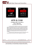
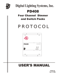
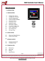
5400 Controller User’s Manual
Table Of Contents
2 INTRODUCTION
3 CONFIGURATION
3
4
5
6
7
8
9
10
11
12
13
14
. . . . Configuration Access
. . . . Configuration Windows
. . . . Factory Configuration
. . . . Inputs & Outputs Window
. . . . Controller History
. . . . Controller Errors
. . . . Controller Events
. . . . USB Import / Export
. . . . Controller Configuration
. . . . Input Configuration
. . . . PID Configuration
. . . . PID Auto Tune
3080852
15 RECIPE EDITING
15 . . . . Recipe and Item Selection
16 . . . . Recipe Item Editing
17 COOKING A RECIPE
17 . . . . Starting A Cook Cycle
18 . . . . Cooking A Recipe
19 TECHNICAL DATA
19 . . . . Dimensions
20 . . . . Mounting
21 . . . . Wiring
22 . . . . Specifications
Page 1
Table of Contents
Notice: Artisan Controls Corporation assumes no responsibility for customers applications or product design. The information and data contained herein is the sole and
exclusive property of Artisan Controls Corporation. Any duplication, misuse, or conversion of this information without the express written consent of Artisan Controls
Corporation is illegal and will result in damages including court costs and attorney fees being assessed against the party misusing this property
Artisan Controls Corporation, 111 Canfield Ave., Bldg B15-18, Randolph, NJ 07869
www.artisancontrols.com
5400 Controller User’s Manual
INTRODUCTION
The Artisan Controls Model 5400 controller provides a modern graphical user interface via it’s 3.5"
diagonal color display and includes two inputs for temperature probes, two switch inputs, two relay
contact outputs, and two DC outputs for driving solid state relays, thereby providing an excellent
platform for heating, cooking, or equipment control for virtually any application.
The 5400 controller also provides a USB port which allows the exporting and importing of the controller
configuration and recipes using USB flash drives. This allows the manufacturer to quickly replicate
standard configurations for various products and end customers.
Refer to the end of this manual for more detailed dimensional
information including installation and wiring
1.50 Max
4.13
Component
Area
3.5
Color LCD Display w/ touchscreen
4.50
Plastic Front Panel
Page 2
Table of Contents
Notice: Artisan Controls Corporation assumes no responsibility for customers applications or product design. The information and data contained herein is the sole and
exclusive property of Artisan Controls Corporation. Any duplication, misuse, or conversion of this information without the express written consent of Artisan Controls
Corporation is illegal and will result in damages including court costs and attorney fees being assessed against the party misusing this property
Artisan Controls Corporation, 111 Canfield Ave., Bldg B15-18, Randolph, NJ 07869
www.artisancontrols.com
5400 Controller User’s Manual
CONFIGURATION ACCESS
Access to the controller configuration has three security levels: Supervisor, Technician, and Factory. The
Supervisor level only has access to the recipe editing, beeper configuration, changing the access code,
temperature display units (°F/°C), and display language. The units and language features are planned future
developments at this time.
To gain access to the configuration, press and hold the area shown below in the main menu list until the
controller emits a double chirp. The initial press will not cause an initial chirp to prevent accidental access
to these features.
Press and hold here
until the double chirp
X
Once the controller chirps twice, release your finger and the access code entry window appears as shown
below. The default supervisor access code is 1234, the factory access code is 9999. Enter the appropriate
code using the numeric keys (a * is displayed for each digit) and press the [Enter] button. The [Delete]
button deletes the last character, [Clear] deletes everything.
Page 3
Table of Contents
Notice: Artisan Controls Corporation assumes no responsibility for customers applications or product design. The information and data contained herein is the sole and
exclusive property of Artisan Controls Corporation. Any duplication, misuse, or conversion of this information without the express written consent of Artisan Controls
Corporation is illegal and will result in damages including court costs and attorney fees being assessed against the party misusing this property
Artisan Controls Corporation, 111 Canfield Ave., Bldg B15-18, Randolph, NJ 07869
www.artisancontrols.com
5400 Controller User’s Manual
CONFIGURATION WINDOWS
There are three levels of access into the controller configuration, Supervisor, Technician, and Factory. Each
level has their own window. The Supervisor level can edit recipes, change their access code, view the
controller history, and change the beeping style at the end of the cooking cycle.
SUPERVISOR LEVEL
CONFIGURATION WINDOW
CODE = “1234”, CHANGEABLE
TECHNICIAN LEVEL
CONFIGURATION WINDOW
CODE = “5142”, NOT CHANGEABLE
ACCESSES I/O WINDOW, CONTROLLER
HISTORY AND USB FUNCTIONS
FACTORY LEVEL
CONFIGURATION WINDOW
CODE = “9999”, NOT CHANGEABLE
ACCESSES ALL TECHNICIAN FUNCTIONS
PLUS CONTROLLER AND COOKING
CONFIGURATION.
Page 4
Table of Contents
Notice: Artisan Controls Corporation assumes no responsibility for customers applications or product design. The information and data contained herein is the sole and
exclusive property of Artisan Controls Corporation. Any duplication, misuse, or conversion of this information without the express written consent of Artisan Controls
Corporation is illegal and will result in damages including court costs and attorney fees being assessed against the party misusing this property
Artisan Controls Corporation, 111 Canfield Ave., Bldg B15-18, Randolph, NJ 07869
www.artisancontrols.com
5400 Controller User’s Manual
FACTORY CONFIGURATION
Entering the factory level password of “9999” opens the Factory Access window shown below.
The [View I/O] button opens a window which shows the states of all inputs, allows the manual activation of
all outputs, and from which the temperature offset from the probe to the visible temperature can be set.
The [History] button opens the controller history window which shows the total number of operating
hours, the total number of cooking hours, and a log of errors and events.
The [Controller] button opens a window from which the controller operation is configured, allowing the
OEM to set the probe type and the temperature control method.
The [Cooking] button opens a window to allow configuration of the recipe timing (hours & minutes or
minutes & seconds), the allowable time value which can be added to a cooking cycle, and other
parameters.
The [Import] button opens the USB Import window from which the recipes and controller configuration can
be imports from a USB flash drive. The [Export] button opens a window from which the recipes and
configuration can be exported.
Page 5
Table of Contents
Notice: Artisan Controls Corporation assumes no responsibility for customers applications or product design. The information and data contained herein is the sole and
exclusive property of Artisan Controls Corporation. Any duplication, misuse, or conversion of this information without the express written consent of Artisan Controls
Corporation is illegal and will result in damages including court costs and attorney fees being assessed against the party misusing this property
Artisan Controls Corporation, 111 Canfield Ave., Bldg B15-18, Randolph, NJ 07869
www.artisancontrols.com
5400 Controller User’s Manual
INPUTS & OUTPUTS WINDOW
Pressing the [I/O] button opens the System I/O window which shows the state of all the inputs and allows
the user to change the state of all system outputs.
K1 & K2: These buttons change the state of the two relay contact outputs. Pressing one of these buttons
will toggle its state (shown my a highlight change) and the state of the output relay.
SSR1 & SSR2: These are the SSR1 and SSR2 outputs, similar to the relay buttons pressing these will toggle its
state and the state of the actual output.
SW1 & SW2: These buttons show the state the SW1 and SW2 inputs, when the inputs are activated the
button turns green.
IN1 & IN2: Temperature of the input probes in 0.1°F increments.
CJC: Temperature of the on board cold junction compensation for thermocouples.
OFFSET: The temperature displayed and used in the PID control can be offset to accommodate sensor
position and calibration. Use the [0.1] and [1.0] buttons to add or subtract to the current offset value
(default = 0.0°F)
NOTE: Exiting this window will set all outputs to their off state
Page 6
Table of Contents
Notice: Artisan Controls Corporation assumes no responsibility for customers applications or product design. The information and data contained herein is the sole and
exclusive property of Artisan Controls Corporation. Any duplication, misuse, or conversion of this information without the express written consent of Artisan Controls
Corporation is illegal and will result in damages including court costs and attorney fees being assessed against the party misusing this property
Artisan Controls Corporation, 111 Canfield Ave., Bldg B15-18, Randolph, NJ 07869
www.artisancontrols.com
5400 Controller User’s Manual
CONTROLLER HISTORY WINDOW
Pressing the [View History] button opens the Controller History windowwhich shows the following:
Total: The total number of hours the controller has been turned on.
Cook: The total number of hours the controller has been cooking which includes preheating.
The scrollable list below the time values shows all of the trackable events and error the controller has
experienced, the controller remembers up the last 128 events. The time of the event (in total running
hours) and a descriptive string are displayed, use the up and down arrows to view the list.
ERRORS: These events cause the controller to halt operation and display the fault in the System Error
screen as the are not recoverable. This window does allow the controller to be rebooted in an attempt to
rectify the fault but that may not work.
This error window has two lines above the CALL
FOR SERVICE line which provide more detailed
information about the type of error
Page 7
Table of Contents
Notice: Artisan Controls Corporation assumes no responsibility for customers applications or product design. The information and data contained herein is the sole and
exclusive property of Artisan Controls Corporation. Any duplication, misuse, or conversion of this information without the express written consent of Artisan Controls
Corporation is illegal and will result in damages including court costs and attorney fees being assessed against the party misusing this property
Artisan Controls Corporation, 111 Canfield Ave., Bldg B15-18, Randolph, NJ 07869
www.artisancontrols.com
5400 Controller User’s Manual
ERRORS
Here is a list of the errors with their descriptive text in the history and error windows:
History Text
Error Window Text
Probe Error
TEMPERATURE PROBE ERROR
The temperature probe is monitored for out of range readings indicating a failure . When a probe value is
out of range the reported temperature is driven to 999.9 degrees to shut down the temperature control. If
the probe returns to normal the temperatures are again used to control temperature in the effort to
continue and complete a current cooking cycle. If the probe remains at 999.9 degrees for 10 seconds the
controller is halted, the red error window is displayed, and the error code and time are written into the
history log.
Tch Scr Error
TOUCHSCREEN ERROR
The resistive touchscreen is monitored in the splash screen for the length of the touch which exits to the
main recipe window. A touch lasting more than 5 seconds will cause a double chirp after which releaseing
the touchscreen will access the touchscreen calibration function. A touch lasting more than 15 seconds
indicate that the touch screen is cracked or contaminated and will cause an error screen and a history log
entry.
NVM-W Error
ERROR SAVING TO MEMORY STORAGE
The controller has detected an problem with writing to its internal non-volatile memory (NVM). All
calibration, configuration, and recipe data is saved in NVM, and an write error causes the error window to
appear and a log entry to be made.
NVM-R Error
ERROR READING FROM MEMORY STORAGE
All critical data written to the NVM is saved with a checksum, and when this information is read from that
memory the checksum is verified. If this first verification fails the data will be read two more times. If the
data does not verify three times the error window is displayed and a log entry is made .
GP Fault
GP FAULT:nnnnnnnn AT ADDR:aaaaaaaa
A general protection fault is when the program attempts to read or write data to an invalid memory
address. The “nnnnnnnn” is the code for the type of internal address, and “aaaaaaaa” is the code address
which caused the fault.
Page 8
Table of Contents
Notice: Artisan Controls Corporation assumes no responsibility for customers applications or product design. The information and data contained herein is the sole and
exclusive property of Artisan Controls Corporation. Any duplication, misuse, or conversion of this information without the express written consent of Artisan Controls
Corporation is illegal and will result in damages including court costs and attorney fees being assessed against the party misusing this property
Artisan Controls Corporation, 111 Canfield Ave., Bldg B15-18, Randolph, NJ 07869
www.artisancontrols.com
5400 Controller User’s Manual
SYSTEM EVENTS
Here is a list of the system events which cause a history log entry:
Factory Rst
Factory Reset is performed as the controller is being tested at the factory. This resets the
recipes and controller configuration to defaults and performs a touchscreen calibration.
Tch Scr Cal
Touch screen calibration, either during the factory reset or performed by the user
Config Chg
This indicates that the controller configuration has been changed which includes Supervisory
or Factory level changes but not PID configuration changes.
PID Cfg Chg
The PID configuration was changed
Access Err
An invalid password was entered
Access Chg
The Supervisor password was changed
Recipe Imp
The recipes were imported from a USB flash drive
Recipe Exp
The recipes were exported to a USB flash drive.
Cfg Import
The controller configuration was imported from a USB flash drive
Cfg Export
The controller configuration was exported to a USB flash drive.
USB Error
The controller was unable to create or find the proper file on the flash drive
Page 9
Table of Contents
Notice: Artisan Controls Corporation assumes no responsibility for customers applications or product design. The information and data contained herein is the sole and
exclusive property of Artisan Controls Corporation. Any duplication, misuse, or conversion of this information without the express written consent of Artisan Controls
Corporation is illegal and will result in damages including court costs and attorney fees being assessed against the party misusing this property
Artisan Controls Corporation, 111 Canfield Ave., Bldg B15-18, Randolph, NJ 07869
www.artisancontrols.com
5400 Controller User’s Manual
USB IMPORT / EXPORT
Pressing the [USB Export] button opens the Save To USB window below. When a USB flash drive is inserted
to the USB port the message changes to “Drive Inserted” and the two buttons below it are activated. To
save the current recipe configuration simply press the [Save Recipes] button and they are saved in a file
named RECIPES.CFG on the flash drive. The same follows for the [Save Config] button, the controller
configuration is saved in a file named CONFIG.CFG and PID configuration in PID.CFG. Once complete you
can remove the flash drive and the controller automatically returns to the OEM configuration window. The
Save History buttons saves the history items to a CSV file named HISTORY.CSV.
Pressing the [USB Import] button opens the Read From USB window below. When a USB flash drive is
inserted to the USB port the message changes to “Drive Inserted” and the two buttons below it are
activated. To read the recipe configuration on the drive simply press the [Read Recipes] button and they
are read from the file RECIPES.CFG on the flash drive and stored in the internal non-volatile memory. The
same follows for the [Read Config] button, the enter controller configuration is read from the CONFIG.CFG
and PID.CFG files. Once complete you can remove the flash drive and the controller automatically returns
to the previous window.
Page 10
Table of Contents
Notice: Artisan Controls Corporation assumes no responsibility for customers applications or product design. The information and data contained herein is the sole and
exclusive property of Artisan Controls Corporation. Any duplication, misuse, or conversion of this information without the express written consent of Artisan Controls
Corporation is illegal and will result in damages including court costs and attorney fees being assessed against the party misusing this property
Artisan Controls Corporation, 111 Canfield Ave., Bldg B15-18, Randolph, NJ 07869
www.artisancontrols.com
5400 Controller User’s Manual
CONTROLLER CONFIGURATION
Pressing the [Controller] button opens this window which shows the current controller configuration.
T Ctrl: Determines the method of temperature control and the configuration of that method. The control
system always uses the first temperature input as the process variable. The button can be pressed to
change from PID to ON/OFF control. The PID control output is always the SSR1 output, in ON/OFF control
the output can be changed between K1 and SSR1 with an adjustable hysteresis value. The [Configure]
button opens either the PID configuration window or the On/Off configuration window
IN1 & IN2: Shows the configuration of the two analog inputs, press [Configure] to change or calibrate the
system analog inputs.
ON/OFF CONFIGURATION
Select the heat output to be used and the control hysteresis here, setting the hysteresis below 3 degrees
automatically changes the Heat Output to SSR1.
Page 11
Table of Contents
Notice: Artisan Controls Corporation assumes no responsibility for customers applications or product design. The information and data contained herein is the sole and
exclusive property of Artisan Controls Corporation. Any duplication, misuse, or conversion of this information without the express written consent of Artisan Controls
Corporation is illegal and will result in damages including court costs and attorney fees being assessed against the party misusing this property
Artisan Controls Corporation, 111 Canfield Ave., Bldg B15-18, Randolph, NJ 07869
www.artisancontrols.com
5400 Controller User’s Manual
INPUT CONFIGURATION
Pressing the [Configure] button for the inputs opens this window which shows the current input
configuration. Press the buttons for IN1 or IN2 to change between J T/C or RTD to select the input type for
your application. The 5400 is pre-calibrated at the factory for both of these input types so calibration by the
user is not required.
If you choose to re-calibrate either of the inputs you must have a thermocouple calibrator or precision 100
ohm and 200 ohm resistors, please contact Artisan for further information. The controller will lead the
technician through a Zero and Gain calibration using the appropriate input value and recalibrate the sensor
input. The thermocouple calibrator must supply a copper connection (not T/C metals) and have CJC
compensation turned off for accurate calibration.
Page 12
Table of Contents
Notice: Artisan Controls Corporation assumes no responsibility for customers applications or product design. The information and data contained herein is the sole and
exclusive property of Artisan Controls Corporation. Any duplication, misuse, or conversion of this information without the express written consent of Artisan Controls
Corporation is illegal and will result in damages including court costs and attorney fees being assessed against the party misusing this property
Artisan Controls Corporation, 111 Canfield Ave., Bldg B15-18, Randolph, NJ 07869
www.artisancontrols.com
5400 Controller User’s Manual
PID CONFIGURATION
Pressing the [Configure] button with PID selected opens the PID Configuration window which displays the
control constants and provides access to auto tuning of the controller and testing of the PID constants
Cycle: This is the output cycling time and PID calculation cycle time in milliseconds , non-adjustable.
Kp, Ki, & Kd: Unit-less PID control constants. These can be edited by touching the item, a numeric entry
window appears and a new value can be entered.
SP: Editable setpoint value used for testing and auto tune.
PV & Out: Real-time values of the current temperature and the output percentage.
Pressing the [Test] button will start the PID control system so the constants can be tested.
The button toggles to the on state and is highlighted when the PID control is running . The PV and Out
values are updated once per second so that the system response can be observed. Pressing the [Test]
button again terminates the PID control. The control system must be turned off before PID constants can
be edited.
Pressing the [SAVE] button saves the PID constants into the non-volatile memory.
NOTE: Exiting this window will halt the PID control system if it is left running.
Pressing the [Auto] button opens the PID Auto Tune window, this process is discussed in detail on the next
page.
Page 13
Table of Contents
Notice: Artisan Controls Corporation assumes no responsibility for customers applications or product design. The information and data contained herein is the sole and
exclusive property of Artisan Controls Corporation. Any duplication, misuse, or conversion of this information without the express written consent of Artisan Controls
Corporation is illegal and will result in damages including court costs and attorney fees being assessed against the party misusing this property
Artisan Controls Corporation, 111 Canfield Ave., Bldg B15-18, Randolph, NJ 07869
www.artisancontrols.com
5400 Controller User’s Manual
PID AUTO TUNING
The PID auto tune in the 5400 controller is a customized Ziegler - Nichols tuning based on the system
performance using relay step / closed loop analysis. The controller uses a setpoint calculated from the
setpoint value entered in the PID Configuration window and then calculates positive and negative offsets
based on that setpoint. The heating output is driven between the high and low percentages, switching back
and forth based on the setpoint and offsets on a thermostatic basis. The auto tune systems runs a total of 6
cycles, 3 to allow the system to stabilize and then 3 to measure the performance of the system and
determine the performance of the system. From these values the Kp, Ki, and Kd constants are calculated.
The closer these percentages are to each other the more accurately the auto tune system can determine
the performance of the environment. On systems with higher heat losses the High percentage needs to be
high in order to get a reasonable change of the temperature from low to high , and conversely highly
insulated systems with low heat loss will need the Low percentage to be lower for the same reason .
The High % value can be changed by pressing the
[edit] button which displays a numeric entry
window. The same same method is used to edit the
Low % value. The upper window on the right side
displays the real-time output percentage and the
window below is the temperature. The two
percentage values are saved in the non-volatile
memory with the other PID configuration
information to simplify additional auto tuning cycles
for maximum control tuning.
Pressing the [START] button begins the auto tune
process, the Status window displays “Cycling”
during the 3 stabilization cycles and “Measuring”
during the 3 analysis cycles. Once the process is
complete the Auto Tune Results window is
displayed showing the current and new PID
constants along with the calculated system
performance values (Ku & Pu). Press the [USE]
button to save these new values and the controller
returns to the PID Configuration window to allow
these new constants to be tested and/or saved.
Page 14
Table of Contents
Notice: Artisan Controls Corporation assumes no responsibility for customers applications or product design. The information and data contained herein is the sole and
exclusive property of Artisan Controls Corporation. Any duplication, misuse, or conversion of this information without the express written consent of Artisan Controls
Corporation is illegal and will result in damages including court costs and attorney fees being assessed against the party misusing this property
Artisan Controls Corporation, 111 Canfield Ave., Bldg B15-18, Randolph, NJ 07869
www.artisancontrols.com
5400 Controller User’s Manual
RECIPE EDITING
Access to the editing of the system recipes follows the same instructions as accessing the supervisor
configuration: Press and hold in the main cooking window, enter the supervisor access code, and then the
Supervisor Access window appears ...
X
Press the [Edit Recipes] button in the configuration
window and the Select Recipe window appears. Use the
up and down arrows to scroll the recipe list until the
desired recipe is shown. Touch the recipe to be edited
and it is highlighted, then press the [E D I T] button and
the recipe configuration is shown in the window and is
ready for editing
The Select Item window shows all the items that make up
that recipe. The first item is the name of the recipe, then
the preheat temperature is shown, then any number of
cook cycles and an optional hold cycle are displayed.
The number of cook and hold cycles displayed are
dependent on the customization of the controller done
by Artisan. The standard 5400 model has three different
cook cycles and a hold cycle.
Press the item desired to be edited, it will be highlighted,
and then press the [EDIT] button to show the editing
window.
Once all changes have been made you must press the
[SAVE] button to store this new recipe into the nonvolatile memory.
Page 15
Table of Contents
Notice: Artisan Controls Corporation assumes no responsibility for customers applications or product design. The information and data contained herein is the sole and
exclusive property of Artisan Controls Corporation. Any duplication, misuse, or conversion of this information without the express written consent of Artisan Controls
Corporation is illegal and will result in damages including court costs and attorney fees being assessed against the party misusing this property
Artisan Controls Corporation, 111 Canfield Ave., Bldg B15-18, Randolph, NJ 07869
www.artisancontrols.com
5400 Controller User’s Manual
NAME & COOK SEGMENT EDITING
Touch and highlight the recipe name in the selection window, then press [EDIT] to load the recipe name
editing window below. It will display the current name in the editing box above the keyboard
Name Editing:
[Clr] button: Clears the editing box of all characters
[Rst] button: Restores the original recipe name
[Del] button: Deletes the last character
[Space] buttons: Adds a space character at the end.
Edit the name using the buttons above and the alphanumeric keyboard and press the [SAVE] buttons to
change the recipe name. Recipe names are limited to 14
characters maximum.
Cook Item Editing:
All recipe segments (preheat, cook, hold) are edited in
the window shown to the left. The [<<] and [>>] buttons
allow the editor to change between all the cooking
segments, and they will wrap around from the last item
to the first item and vice versa.
The color of the value fields and the buttons show which
item is being edited, red = active item. Cook segments
have a a time and a temperature, pressing the grey [<]
button switches to that item. Use the dial to the right or
the [+] and [-] buttons to change the value. Press [SAVE]
to save the current values then use the [<<] or [>>]
buttons to select the next item to edit. Press the red [X]
button to return to the item selection window.
NOTE: Preheat and hold segments only have a
temperature value, the time field and [<] button are
greyed out and non selectable.
Page 16
Table of Contents
Notice: Artisan Controls Corporation assumes no responsibility for customers applications or product design. The information and data contained herein is the sole and
exclusive property of Artisan Controls Corporation. Any duplication, misuse, or conversion of this information without the express written consent of Artisan Controls
Corporation is illegal and will result in damages including court costs and attorney fees being assessed against the party misusing this property
Artisan Controls Corporation, 111 Canfield Ave., Bldg B15-18, Randolph, NJ 07869
www.artisancontrols.com
5400 Controller User’s Manual
COOKING A RECIPE
Touch and highlight the recipe name in the selection window, then press [VIEW] to view the recipe details
as shown in the window to the right. Press the [C O O K] button to open the window showing the
[PREHEAT] and [C O O K] buttons in order to start cooking
Touching the [T] button will display the
current oven temperature. Press the
[PREHEAT] or [C O O K] buttons to start
cooking.
The cooking progress is displayed in the
above window. See the next page for
more details
Page 17
Table of Contents
Notice: Artisan Controls Corporation assumes no responsibility for customers applications or product design. The information and data contained herein is the sole and
exclusive property of Artisan Controls Corporation. Any duplication, misuse, or conversion of this information without the express written consent of Artisan Controls
Corporation is illegal and will result in damages including court costs and attorney fees being assessed against the party misusing this property
Artisan Controls Corporation, 111 Canfield Ave., Bldg B15-18, Randolph, NJ 07869
www.artisancontrols.com
5400 Controller User’s Manual
COOKING WINDOW
This is the main cooking window displayed during all cook cycles
The window displays “Preheating” during the preheating cycle, once the oven is up to temperature the
controller beeps, displays “Ready To Cook”, and enables the [COOK] buttons. Pressing the [COOK] button
starts the first cooking segment and automatically proceeds through all cooking cycles , the progress bar
at the bottom shows the progress thru the sum of all the cooking cycle times .
Pressing the [T] button changes the “Temp:” to “Oven:” and displays the real-time oven temperature for
10 seconds then reverts to the setpoint temperature for the current segment.
The [Ex] button automatically adds the preset extra time to the current cook cycle, and in the holding
cycle the controller will revert back to the last cooking cycle for the added time to cook for a longer
period of time.
If the controller customizing has only one cook cycle the cooking segment icons in the upper left corner
are not displayed.
To stop a cooking cycle, press and hold the red [X] button until the controller chirps twice and the system
returns to the preheat / cook selection window.
Page 18
Table of Contents
Notice: Artisan Controls Corporation assumes no responsibility for customers applications or product design. The information and data contained herein is the sole and
exclusive property of Artisan Controls Corporation. Any duplication, misuse, or conversion of this information without the express written consent of Artisan Controls
Corporation is illegal and will result in damages including court costs and attorney fees being assessed against the party misusing this property
Artisan Controls Corporation, 111 Canfield Ave., Bldg B15-18, Randolph, NJ 07869
www.artisancontrols.com
Plastic Front Panel
0.05
0.43
0.32
2.52
2.07
4.50
3.75
3.50
4.13
0.25
0.36
0.38
3.03
2.76
LCD Active Area
Color LCD Display w/ touchscreen
r
0.13
0.196
Dia
1.50 Max
0.12
Component
Area
5400 Controller User’s Manual
Page 19
Table of Contents
Notice: Artisan Controls Corporation assumes no responsibility for customers applications or product design. The information and data contained herein is the sole and
exclusive property of Artisan Controls Corporation. Any duplication, misuse, or conversion of this information without the express written consent of Artisan Controls
Corporation is illegal and will result in damages including court costs and attorney fees being assessed against the party misusing this property
Artisan Controls Corporation, 111 Canfield Ave., Bldg B15-18, Randolph, NJ 07869
www.artisancontrols.com
Front Sheet
Metal
4.50 REF
3.75
0.37
3.50
4.13
REF
0.25
0.33
0.38
3.10
3.10 x 2.63 Cutout
In front sheet metal
0.062 max corner R
2.63
#8 Male Stud, ½”
Far side, 4 places
Controller
5400 Controller User’s Manual
Page 20
Table of Contents
Notice: Artisan Controls Corporation assumes no responsibility for customers applications or product design. The information and data contained herein is the sole and
exclusive property of Artisan Controls Corporation. Any duplication, misuse, or conversion of this information without the express written consent of Artisan Controls
Corporation is illegal and will result in damages including court costs and attorney fees being assessed against the party misusing this property
Artisan Controls Corporation, 111 Canfield Ave., Bldg B15-18, Randolph, NJ 07869
www.artisancontrols.com
SW2
SW1
R2
SSR2
R1
SSR1
5400 Controller User’s Manual
USB
Port
IN1
+5V DC
IN2
Analog Ground
Earth Ground
Hot
Note: Hot connections
tied together on PCB
AC POWER
Page 21
Table of Contents
Notice: Artisan Controls Corporation assumes no responsibility for customers applications or product design. The information and data contained herein is the sole and
exclusive property of Artisan Controls Corporation. Any duplication, misuse, or conversion of this information without the express written consent of Artisan Controls
Corporation is illegal and will result in damages including court costs and attorney fees being assessed against the party misusing this property
Artisan Controls Corporation, 111 Canfield Ave., Bldg B15-18, Randolph, NJ 07869
www.artisancontrols.com
5400 Controller User’s Manual
SPECIFICATIONS:
LCD DISPLAY: Color 3.5" diagonal TFT display, 320 x 240 pixels, 16 bit color, resistive touchscreen, 300 nits
minimum.
INPUTS:
SW1 & SW2: Low voltage dry contact inputs, <5mA @ 5VDC
IN1 & IN2: Universal analog inputs. Software configurable for 100 Ohm RTD (385 or 392 curve), J or K
thermocouple, other analog inputs (ie: 4-20mA, 0-10V) available. +5V DC for sensor power limited to 50mA
maximum2.
OUTPUTS:
R1 & R2: SPNO relay contacts rated 10A @ 125V, 7A @ 250V.
SSR1 & SSR2: 5VDC @ 50mA maximum2.
FUNCTIONALITY:
Up to 15 menu selections, multiple cook cycles, thermostatic or PID control, custom windows, logos, and
control schemes available.
ARCHITECTURE:
Microcontroller: 32 bit processor, 80MHz, w/floating point.
Graphics: Epson graphics controller, 60 fps refresh rate
Measurement: 16 bit A/D converter.
USB PORT:
Flash drive interface for importing & exporting cooking recipes and controller configuration.
CONNECTIONS:
Supply: Wago 231-134/001-000
Input/Output: Wago 231-140/001-000
Analog Inputs: Rising cage w/screw, 16-30 GA
ENVIRONMENTAL:
PCB’s: Edge sealed to each other with RTV to prevent penetration of moisture or other contaminants.
Operating Temperature: 0°C to +70°C
AC POWER: 90-265VAC, 50/60Hz, 5W maximum
RECOGNITIONS:
Conforms to UL STDS 60730-1 & 60730-2-9
Certified to CSA STDS E60730-1 & E60730-2-9
2
- Total external 5VDC current draw = 80mA maximum.
3080852
Page 22
Table of Contents
Notice: Artisan Controls Corporation assumes no responsibility for customers applications or product design. The information and data contained herein is the sole and
exclusive property of Artisan Controls Corporation. Any duplication, misuse, or conversion of this information without the express written consent of Artisan Controls
Corporation is illegal and will result in damages including court costs and attorney fees being assessed against the party misusing this property
Artisan Controls Corporation, 111 Canfield Ave., Bldg B15-18, Randolph, NJ 07869
www.artisancontrols.com