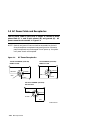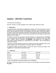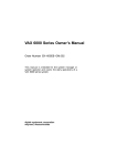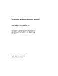
1
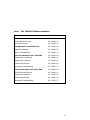
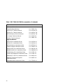
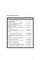
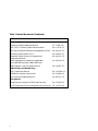
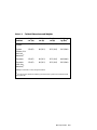
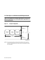
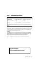
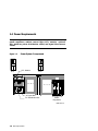
DEC 7000 AXP System
VAX 7000
Site Preparation Guide
Order Number EK–7000B–SP.002
This guide is intended for use by Digital customer service engineers and
customers in preparing a site for a DEC 7000 AXP system or VAX 7000
system.
digital equipment corporation
maynard, massachusetts
First Printing, November 1992
The information in this document is subject to change without notice and should
not be construed as a commitment by Digital Equipment Corporation.
Digital Equipment Corporation assumes no responsibility for any errors that may
appear in this document.
The software, if any, described in this document is furnished under a license and
may be used or copied only in accordance with the terms of such license. No responsibility is assumed for the use or reliability of software or equipment that is
not supplied by Digital Equipment Corporation or its affiliated companies.
Copyright © 1992 by Digital Equipment Corporation.
All Rights Reserved.
Printed in U.S.A.
The following are trademarks of Digital Equipment Corporation:
Alpha AXP
AXP
DEC
DECchip
DEC LANcontroller
DECnet
DECUS
DWMVA
OpenVMS
ULTRIX
UNIBUS
VAX
VAXBI
VAXELN
VMScluster
XMI
The AXP logo
dT
OSF/1 is a registered trademark of the Open Software Foundation, Inc.
FCC NOTICE: The equipment described in this manual generates, uses, and may
emit radio frequency energy. The equipment has been type tested and found to
comply with the limits for a Class A computing device pursuant to Subpart J of
Part 15 of FCC Rules, which are designed to provide reasonable protection against
such radio frequency interference when operated in a commercial environment.
Operation of this equipment in a residential area may cause interference, in which
case the user at his own expense may be required to take measures to correct the
interference.
Contents
Preface ....................................................................................................... v
Chapter 1 Site Preparation
1.1
1.2
1.3
1.4
1.5
Pre-Installation Checklist ..................................................... 1-2
Cabinet Sizes .......................................................................... 1-4
Floor Space and Environmental Requirements ................... 1-6
Power Requirements .............................................................. 1-8
AC Power Cable and Receptacles ........................................ 1-10
Figures
1-1
1-2
1-3
1-4
Sample System ....................................................................... 1-4
Sample Configuration ............................................................ 1-6
Power System Components ................................................... 1-8
AC Power Receptacles .......................................................... 1-10
Tables
1
2
1-1
1-2
1-3
1-4
1-5
DEC 7000/VAX 7000 Documentation .................................... vii
Related Documents .................................................................. ix
Shipping Dimensions and Weights ....................................... 1-3
Cabinet Dimensions and Weights ......................................... 1-5
Environmental Specifications ............................................... 1-7
AC Input Voltages .................................................................. 1-9
Power Requirements .............................................................. 1-9
iii
iv
Preface
Intended Audience
This manual is written for Digital customer service engineers and customers preparing a site for a DEC 7000 or VAX 7000 system.
Document Structure
This manual uses a structured documentation design. Topics are organized into small sections for efficient on-line and printed reference. Each
topic begins with an abstract. You can quickly gain a comprehensive overview by reading only the abstracts. Next is an illustration or example,
which also provides quick reference. Last in the structure are descriptive
text and syntax definitions.
This manual has one chapter, as follows:
•
Chapter 1, Site Preparation, provides pre-installation requirements and guidelines for DEC 7000 and VAX 7000 systems.
v
Conventions Used in This Document
Terminology. Unless specified otherwise, the use of "system" refers to
either a DEC 7000 AXP or VAX 7000 system. The DEC 7000 AXP systems
use the Alpha AXP architecture. References in text use DEC 7000 to refer
to DEC 7000 AXP systems.
When a discussion applies to only one system, an icon is used to highlight
that system. Otherwise, the discussion applies to both systems. Thus, the
abstract for a module that applies only to DEC 7000 systems would look
like this:
This section shows a sample boot of OpenVMS Alpha AXP
DEC from the RRD42 CD drive for DEC 7000 systems. The first
7000
step is issuing the show device command to determine the
location of the RRD42.
Book titles. In text, if a book is cited without a product name, that book is
part of the hardware documentation. It is listed in Table 1 along with its
order number.
Icons. The icons shown below are used in illustrations for designating part
placement in the system described. A shaded area in the icon shows the
location of the component or part being discussed.
Front
Rear
Documentation Titles
Table 1 lists the books in the DEC 7000 and VAX 7000 documentation set.
Table 2 lists other documents that you may find useful.
vi
Table 1
DEC 7000/VAX 7000 Documentation
Title
Order Number
Installation Kit
EK–7000B–DK
Site Preparation Guide
EK–7000B–SP
Installation Guide
EK–700EB–IN
Hardware User Information Kit
EK–7001B–DK
Operations Manual
EK–7000B–OP
Basic Troubleshooting
EK–7000B–TS
Service Information Kit—VAX 7000
EK–7002A–DK
Platform Service Manual
EK–7000A–SV
System Service Manual
EK–7002A–SV
Pocket Service Guide
EK–7000A–PG
Advanced Troubleshooting
EK–7001A–TS
Service Information Kit—DEC 7000
EK–7002B–DK
Platform Service Manual
EK–7000A–SV
System Service Manual
EK–7002B–SV
Pocket Service Guide
EK–7700A–PG
Advanced Troubleshooting
EK–7701A–TS
vii
Table 1 DEC 7000/VAX 7000 Documentation (Continued)
Title
Order Number
Reference Manuals
Console Reference Manual
EK–70C0B–TM
KA7AA CPU Technical Manual
EK–KA7AA–TM
KN7AA CPU Technical Manual
EK–KN7AA–TM
MS7AA Memory Technical Manual
EK–MS7AA–TM
I/O System Technical Manual
EK–70I0A–TM
Platform Technical Manual
EK–7000A–TM
Upgrade Manuals
KA7AA CPU Installation Guide
EK–KA7AA–IN
KN7AA CPU Installation Guide
EK–KN7AA–IN
MS7AA Memory Installation Guide
EK–MS7AA–IN
KZMSA Adapter Installation Guide
EK–KXMSX–IN
DWLMA XMI PIU Installation Guide
EK–DWLMA–IN
DWMBB VAXBI PIU Installation Guide
EK–DWMBB–IN
H7237 Battery PIU Installation Guide
EK–H7237–IN
H7263 Power Regulator Installation Guide
EK–H7263–IN
BA654 DSSI Disk PIU Installation Guide
EK–BA654–IN
BA655 SCSI Disk and Tape PIU
Installation Guide
EK–BA655–IN
Removable Media Installation Guide
EK–TFRRD–IN
viii
Table 2 Related Documents
Title
Order Number
General Site Preparation
Site Environmental Preparation Guide
EK–CSEPG–MA
System I/O Options
BA350 DECstor/me Modular Storage Shelf
Subsystem Configuration Guide
EK–BA350–CG
BA350 DECstor/me Modular Storage Shelf
Subsystem User’s Guide
EK–BA350–UG
BA350-LA DECstor/me Modular Storage Shelf
User’s Guide
EK–350LA–UG
CIXCD Interface User Guide
EK–CIXCD–UG
DEC FDDIcontroller 400 Installation/Problem
Solving
EK–DEMFA–IP
DEC LANcontroller 400 Installation Guide
EK–DEMNA–IN
DEC LANcontroller 400 Technical Manual
EK–DEMNA–TM
DSSI VAXcluster Installation and Troubleshooting
Manual
EK–410AA–MG
InfoServer 150 Installation and Owner’s Guide
EK–INFSV–OM
KDM70 Controller User Guide
EK–KDM70–UG
KFMSA Module Installation and User Manual
EK–KFMSA–IM
KFMSA Module Service Guide
EK–KFMSA–SV
RRD42 Disc Drive Owner’s Manual
EK–RRD42–OM
RF Series Integrated Storage Element User Guide
EK–RF72D–UG
TF85 Cartridge Tape Subsystem Owner’s Manual
EK–OTF85–OM
TLZ06 Cassette Tape Drive Owner’s Manual
EK–TLZ06–OM
ix
Table 2 Related Documents (Continued)
Title
Order Number
Operating System Manuals
Alpha Architecture Reference Manual
EY–L520E–DP
DEC OSF/1 Guide to System Administration
AA–PJU7A–TE
DECnet for OpenVMS Network Management Utilities
AA–PQYAA–TK
Guide to Installing DEC OSF/1
AA–PS2DA–TE
OpenVMS Alpha Version 1.0 Upgrade and
Installation Manual
AA–PQYSA–TE
VMS Upgrade and Installation Supplement:
VAX 7000–600 and VAX 10000–600 Series
AA–PRAHA–TE
VMS Network Control Program Manual
AA–LA50A–TE
VMSclusters and Networking
HSC Installation Manual
EK–HSCMN–IN
SC008 Star Coupler User’s Guide
EK–SC008–UG
VAX Volume Shadowing Manual
AA–PBTVA–TE
Peripherals
x
Installing and Using the VT420 Video Terminal
EK–VT420–UG
LA75 Companion Printer Installation and User Guide
EK–LA75X–UG
Chapter 1
Site Preparation
This chapter provides site planning guidelines, cabinet sizes, space and environmental requirements, and system power requirements.
Sections include:
•
Pre-Installation Checklist
•
Cabinet Sizes
•
Floor Space and Environmental Requirements
•
Power Requirements
•
AC Power Cable and Connectors
Site Preparation 1-1
1.1 Pre-Installation Checklist
Site planning guidelines and tasks are listed below. The tasks can
be checked off when completed before system delivery. To facilitate the installation process, it is recommended that the customer
plan ahead and coordinate the site planning and scheduling details with Digital.
Planning the Site:
b
b
b
b
b
b
b
b
b
b
1-2
Plan the physical layout of the system cabinet, expander cabinets, console terminal, and other system units.
Plan to place all equipment away from heavy traffic centers leaving
enough room for airflow and maintenance.
Obtain cabinet weights and dimensions to check against floor loading
restrictions.
Determine the sizes of circuit breakers and the number of branch circuits required.
Determine number, type, and location of required AC power outlets.
Check the compatibility of different power sources. This must be
checked when multiple types of power distribution transformers, or
power conditioning equipment is used.
Determine system power consumption to calculate the input line power
requirement.
Establish a system grounding scheme for the installation.
Determine environmental cooling requirements.
Check the location and requirements of cabling for communication devices such as Ethernet.
Site Preparation
Checking the Delivery Route:
b
b
b
b
Check the height, width, and location of doors and passageways for
adequate clearance.
Check floor loading requirements along passageways.
Check passageway restrictions such as corners, ramps, or obstructions.
Check the size, capacity, and availability of elevators.
Table 1-1 lists the shipping dimensions for the system and expander cabinets. These dimensions include the width of the shipping pallet, the
height of the shipping boxes, and the weight of the packing materials.
Table 1-1
Shipping Dimensions and Weights
Cabinet
Height
cm (in)
Width
cm (in)
Depth
cm (in)
Weight
1
kg (lbs)
System
195 (76.8)
109.5 (43.1)
121 (47.5)
448 (1000)
System
(Battery PIU
with four
batteries)2
195 (76.8)
109.5 (43.1)
121 (47.5)
585 (1300)
Expander
195 (76.8)
109.5 (43.1)
121 (47.5)
495 (1100)
Expander
(with four
batteries)2
195 (76.8)
109.5 (43.1)
121 (47.5)
632 (1393)
1 Weights are based on a fully configured cabinet.
2 For systems with 8 batteries add 62 kg (137 lbs) and for systems with 12 batteries add
124 kg (274 lbs).
For more information:
Site Environmental Preparation Guide
Site Preparation 1-3
1.2 Cabinet Sizes
Include all cabinets and peripherals when laying out the installation site. A sample system could include a main cabinet, a maximum of two expander cabinets, and console devices.
Figure 1-1
Sample System
170 cm (67 in)
Expander
Cabinet
170 cm (67 in)
System
Cabinet
170 cm (67 in)
Expander
Cabinet
80 cm (31.5 in)
80 cm (31.5 in)
80 cm (31.5 in)
BXB-0001B-92
1-4
Site Preparation
Table 1-2
Cabinet Dimensions and Weights
Cabinet
Height
cm (in)
Width
cm (in)
Depth
cm (in)
Weight
1
kg (lbs)
System
170 (67)
80 (31.5)
87.5 (34.5)
408 (900)
System
(Battery PIU
with four
batteries)2
170 (67)
80 (31.5)
87.5 (34.5)
545 (1200)
Expander
170 (67)
80 (31.5)
87.5 (34.5)
448 (1000)
Expander
(with four
batteries)2
170 (67)
80 (31.5)
87.5 (34.5)
585 (1300)
1 Weights are based on a fully configured cabinet.
2 For systems with 8 batteries add 62 kg (137 lbs) and for systems with 12 batteries add
124 kg (274 lbs).
Site Preparation 1-5
1.3 Floor Space and Environmental Requirements
Table 1-3 lists system environmental requirements. Front and rear
clearance specifications are the minimum space required for airflow and maintenance.
Figure 1-2
Sample Configuration
Rear
Clearance
100 cm (39 in)
Expander
Cabinet
System
Cabinet
Width
240 cm (94.5 in)
Expander
Cabinet
87.5 cm
(34.5 in)
Depth
337.5 cm (132 in)
Front
Clearance
150 cm (59 in)
BXB-0001A-92
NOTE: Do not place anything on the top of the cabinets, as this restricts
airflow. The console terminal and printer can be placed on a table
near the system.
1-6
Site Preparation
Table 1-3
Environmental Specifications
Environmental
Operating
Storage
Temperature1
15°–28° C (59°–82° F)
-40°–66° C (-40°–151° F)
Relative humidity1
20–80%
10–95%
Altitude
0–2.4 km (0–8000 ft)
0–9.1 km (0–30,000 ft)
1Recommended operating temperature is 18°–24° C (65°–75° F) and 40–60% relative humidity.
The minimum amount of clearance space for the system front is 150 cm (59
in) and rear is 100 cm (39 in), as shown in Figure 1-2. These clearances
are needed for airflow and maintenance.
Airflow
Air is taken in through the top and bottom of the cabinet by a dual wheel
blower. The air is then circulated through the card cages and power regulators. It is vented at the middle of the cabinet front and rear.
NOTE: Inadequate airflow can result in the system shutting down,
For more information:
Site Environmental Preparation Guide
Site Preparation 1-7
1.4 Power Requirements
The power system includes an AC input box, DC distribution box,
power regulators, cabinet control logic (CCL) module, optional
48V batteries, power distribution cables, and signal interconnect
cables.
Figure 1-3
Rear
Power System Components
CCL Module
Front
AC Input Box
DC Distribution Box
Power
Regulators
BXB-0052-92
1-8
Site Preparation
Table 1-4
AC Input Voltages
Country
Input
Voltage
Circuit Breaker
1
Rating (amps)
Frequency
Range (Hz)
Japan
202 Delta
30
50–60
North America
120/208 Wye
30
50–60
Europe/GIA
380–415 Wye
16
50–60
1Each system and expander cabinet requires its own AC power connector.
Table 1-5
Power Requirements
Cabinet
Power (watts)
Heat Dissipation (BTU/hr)
System
1,000 minimum1
5,200 maximum2
3,400 minimum1
17,700 maximum2
System and
2 expanders
13,800 maximum2
47,000 maximum2
1A minimum configuration consists of one CPU module, one memory module, one IOP
module, one XMI PIU, one Ethernet I/O bus adapter module, and one disk I/O bus
adapter module.
2These requirements are based on a fully loaded system.
NOTE: AC power receptacles are also required for console terminals and
printers.
Site Preparation 1-9
1.5 AC Power Cable and Receptacles
The AC power cable is 2.8 m (9 ft) in length. It consists of threephase leads (X, Y, and Z) plus neutral (N) and ground (G). AC
power connectors are shown in Figure 1-4.
NOTE: Neutral and ground lines must both be connected from the bulk
three-phase power to complete the Wye configuration. Otherwise,
power components may be damaged. Do not power up the system
until power checks are completed.
Figure 1-4
AC Power Receptacles
202 V NOMINAL (50-60 Hz)
NEMA L21-30R
120/208 V NOMINAL (50-60 Hz)
NEMA L21-30R
V
V
V
V
PHASE X
PHASE X
PHASE Y
PHASE Y
NEUTRAL
GND
GND
PHASE Z
PHASE Z
V
V
380-415 V NOMINAL (50-60 Hz)
IEC 309 TYPE
V
V
PHASE 3
PHASE 2
NEUTRAL
PHASE 1
GND
V
BXB-0040A-92
1-10
Site Preparation
Index
A
G
AC current ratings, 1-9
AC input voltages, 1-9
AC power cables, 1-10
AC power connectors, 1-10
AC power outlets, 1-2
Air circulation, 1-7
Altitude, 1-7
Grounding, 1-2
B
Operating characteristics, 1-7
Backup batteries, 1-8
Branch circuits, 1-2
P
C
Cabinet sizes, 1-4
Cables
signal interconnect, 1-8
Communications devices, 1-2
D
DC distribution box, 1-8
Delivery route checking, 1-3
E
H
Heat dissipation, 1-9
Humidity, 1-7
O
Power
distribution cables, 1-8
requirements, 1-8
sources, 1-2
watts, 1-9
Pre-installation checklist, 1-2
R
Rear clearance, 1-6
S
F
Shipping
dimensions, 1-3
weights, 1-3
Site circuit breakers, 1-2
Site planning guidelines, 1-2
System cabinet
specifications, 1-5
Floor space, 1-6
Front clearance, 1-6
T
Environmental specifications, 1-7
Expander cabinet
specifications, 1-5
Temperature, 1-7
Index-1