1
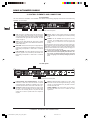
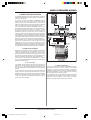
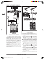
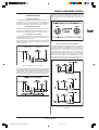
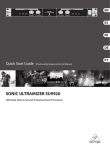
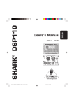
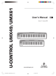
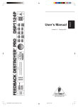
Version 1.0
SONIC ULTRAMIZER
SU9920
User Manual
01_DATA-MANFULL_SU9920_487_EN_Rev_A.pmd
1
19.04.2007, 14:43
April 2007
SONIC ULTRAMIZER SU9920
IMPORTANT SAFETY INSTRUCTIONS
14) Use only with the cart, stand, tripod, bracket, or table
specified by the manufacturer, or sold with the
apparatus. When a cart is used, use caution when
moving the cart/apparatus combination to avoid injury
from tip-over.
CAUTION:
To reduce the risk of electric shock, do not remove the top
cover (or the rear section). No user serviceable parts inside.
Refer servicing to qualified personnel.
WARNING:
To reduce the risk of fire or electric shock, do not expose
this appliance to rain and moisture. The apparatus shall not
be exposed to dripping or splashing liquids and no objects
filled with liquids, such as vases, shall be placed on the
apparatus.
This symbol, wherever it appears, alerts you to
the presence of uninsulated dangerous voltage
inside the enclosure - voltage that may be
sufficient to constitute a risk of shock.
This symbol, wherever it appears, alerts you to
important operating and maintenance instructions
in the accompanying literature. Please read the
manual.
15) Unplug this apparatus during lightning storms or when
unused for long periods of time.
16) Refer all servicing to qualified service personnel.
Servicing is required when the apparatus has been
damaged in any way, such as power supply cord or plug
is damaged, liquid has been spilled or objects have fallen
into the apparatus, the apparatus has been exposed to
rain or moisture, does not operate normally, or has been
dropped.
17) Caution! - These service instructions are for use by
qualified service personnel only. To reduce the risk of
electric shock do not perform any servicing other than
that contained in the operation instructions. Repairs
have to be performed by qualified service personnel.
1) Read these instructions.
2) Keep these instructions.
3) Heed all warnings.
4) Follow all instructions.
5) Do not use this apparatus near water.
6) Clean only with dry cloth.
7) Do not block any ventilation openings. Install in
accordance with the manufacturer’s instructions.
8) Do not install near any heat sources such as radiators,
heat registers, stoves, or other apparatus (including
amplifiers) that produce heat.
9) Do not defeat the safety purpose of the polarized or
grounding-type plug. A polarized plug has two blades
with one wider than the other. A grounding type plug
has two blades and a third grounding prong. The wide
blade or the third prong are provided for your safety. If
the provided plug does not fit into your outlet, consult
an electrician for replacement of the obsolete outlet.
10) Place the power cord so that it is protected from being
walked on and sharp edges. Be sure that the power cord
is protected particularly at plugs, convenience
receptables and the point where it exits from the
apparatus.
11) The apparatus shall be connected to a MAINS socket
outlet with a protective earthing connection.
12) Where the MAINS plug or an appliance coupler is used
as the disconnect device, the disconnect device shall
remain readily operable.
13) Only use attachments/accessories specified by the
manufacturer.
2
01_DATA-MANFULL_SU9920_487_EN_Rev_A.pmd
2
19.04.2007, 14:43
SONIC ULTRAMIZER SU9920
SONIC ULTRAMIZER
Ultimate Stereo Sound Enhancement Processor
SU9920
Dramatically improves your sound by adding clarity, dimension and depth
Produces natural brightness through harmonic enhancement and tighter bass with increased punch
through phase compensation
Professional and home recording studios: brings out the full sound spectrum of your tracks, mixdown
and mastering
PA, nightclub and DJ systems: improves the performance of any sound system by adding sparkling
high end and super-tight bass without the need for additional speakers or amps
Churches and worship houses: dramatically increases voice intelligibility and your music gains presence
Guitar, bass and keyboard rack: improves articulation and restores cutting power often lost in miking
and amplification
Broadcasting and webcasting: adds loudness and "live presence" even on small car or computer speakers
5.1 and hi-fi setups: DVDs become stunningly lifelike and the spatial dimension of your sound system
increases dramatically
Dedicated Low contour and Process controls per channel for ultimate sound enhancement
Accurate 5-segment LED level meters for optimum performance
Servo-balanced inputs and outputs with ¼" TRS and gold-plated XLR connectors
High-quality components and exceptionally rugged construction ensure long life
Conceived and designed by BEHRINGER Germany
3
01_DATA-MANFULL_SU9920_487_EN_Rev_A.pmd
3
19.04.2007, 14:43
SONIC ULTRAMIZER SU9920
FOREWORD
Dear Customer,
Welcome to the team of
SONIC ULTRAMIZER
users, and thank you
very much for expressing
your confidence in us by
purchasing this device.
Writing this foreword for
you gives me great
pleasure, because it
represents the culmination of many
months of hard work
delivered
by
our
engineering team to
achieve a very ambitious
goal: to present an
o u t s t a n d i n g
Psychoacoustic
Processor,
whose
neutral sound makes
them ideal for studio use. The task of designing our new SU9920
certainly meant a great deal of responsibility, which we assumed
by focusing on you, the discerning user and musician. Meeting
your expectations also meant a lot of work and night shifts. But
it was fun, too. Developing a product usually brings a lot of people
together. What a great feeling it is when all who participated in
such a project can be proud of what they’ve achieved.
TABLE OF CONTENTS
1. INTRODUCTION .................................................................. 5
1.1 Before you get started ................................................... 5
1.1.1 Shipment ............................................................... 5
1.1.2 Initial operation ..................................................... 5
1.1.3 Online Registration ............................................... 5
2. CONTROL ELEMENTS AND CONNECTIONS ................. 6
2.1 Front panel ..................................................................... 6
2.2 Rear panel ...................................................................... 6
3. PRACTICAL APPLICATION ............................................... 7
3.1 Application examples ..................................................... 7
3.1.1 Live sound ............................................................ 7
3.1.2 Studio application ................................................. 7
3.1.3 Stage operation with instrument amplifiers ......... 8
3.2 Basic operation .............................................................. 8
4. INSTALLATION .................................................................... 9
4.1 Rack mounting ............................................................... 9
4.2 Audio connections .......................................................... 9
4.2.1 Cabling with jack cables ...................................... 9
4.2.2 Connection with insert cables .............................. 9
5. SPECIFICATIONS ............................................................. 10
6. WARRANTY ....................................................................... 11
It is our philosophy to share our enjoyment with you, because
you are the most important member of the BEHRINGER team.
With your highly competent suggestions for new products you’ve
made a significant contribution to shaping our company and
making it successful. In return, we guarantee you
uncompromising quality as well as excellent technical and audio
properties at an extremely reasonable price. All of this will enable
you to give free rein to your creativity without being hampered
by budget constraints.
We are often asked how we manage to produce such high-quality
devices at such unbelievably low prices. The answer is quite
simple: it’s you, our customers! Many satisfied customers mean
large sales volumes, enabling us to get better purchasing terms
for components, etc. Isn’t it only fair to pass this benefit on to
you? Because we know that your success is our success too!
I would like to thank all of you who have made the SU9920
possible. From the developers to the many other employees at
this company, each has made a personal contribution to you,
the BEHRINGER user.
My friends, it’s been worth the effort!
Thank you very much,
Uli Behringer
4
01_DATA-MANFULL_SU9920_487_EN_Rev_A.pmd
4
19.04.2007, 14:43
SONIC ULTRAMIZER SU9920
1.1.3 Online Registration
1. INTRODUCTION
Thank you for purchasing the SONIC ULTRAMIZER SU9920.
The SU9920 is a professional signal processor used to improve
the presence and liveliness of audio signals. For signal
processing a combination of a dynamic filter and a phase delay
algorithm is used. The latter is based on psychoacoustic
principles and guarantees improved sound characteristics
without unnatural side effects. The unit works with two
independent channels, so you can selectively process stereo or
two mono signals separately from each other. Whether you
purchased the SU9920 for your studio, live sound or the stage,
the unit's sound qualities are so impressive that you'll never
again want to do without this sound enhancer when mixing.
We at BEHRINGER hope you enjoy your new acquisition.
1.1 Before you get started
1.1.1 Shipment
Your product was carefully packed at the factory to ensure safe
transport. Nevertheless, if the box is damaged inspect the unit
immediately for signs of damage.
Please register your new BEHRINGER equipment right after
your purchase by visiting http://www.behringer.com and read
the terms and conditions of our warranty carefully.
Should your BEHRINGER product malfunction, it is our intention
to have it repaired as quickly as possible. To arrange for warranty
service, please contact the BEHRINGER retailer from whom
the equipment was purchased.
Should your BEHRINGER dealer not be located in your vicinity,
you may directly contact one of our subsidiaries. Corresponding
contact information is included in the original equipment
packaging (Global Contact Information/European Contact
Information).
Should your country not be listed, please contact the distributor
nearest you. A list of distributors can be found in the support
area of our website (http://www.behringer.com). Registering your
purchase and equipment with us helps us process your repair
claims more quickly and efficiently.
Thank you for your cooperation!
If the unit is damaged please do NOT return it to us,
but notify your dealer and the shipping company
immediately; otherwise, claims for damage or
replacement may not be granted.
We recommend that you use a flight case to give the
unit optimum protection during use or transport.
Always use the original box to prevent damage during
storage or transport.
Make sure that children cannot play unsupervised with
the unit or its packaging.
Please ensure proper disposal of all packing materials.
1.1.2 Initial operation
Ensure adequate air supply and to avoid overheating do not
place the unit near radiators etc.
Blown fuses must be replaced by fuses of the correct
rating! Please refer to the "SPECIFICATIONS" section
for the applicable rating.
For connection to the mains use the enclosed power cord with
cold connector which complies with the relevant safety
regulations.
Please make sure that all devices are properly
grounded. For your own safety, never remove or
disable the ground conductors from the devices or on
the power cords. The unit must always be connected
to the mains outlet with a protective grounding
connection.
The tone quality may diminish within the range of
powerful radio broadcasting stations and highfrequency sources. Increase the distance between the
transmitter and the unit, and use shielded cables for
all connections.
5
1. INTRODUCTION
01_DATA-MANFULL_SU9920_487_EN_Rev_A.pmd
5
19.04.2007, 14:43
SONIC ULTRAMIZER SU9920
2. CONTROL ELEMENTS AND CONNECTIONS
2.1 Front panel
The control elements for CHANNEL 1 and CHANNEL 2 are identical. In the following paragraphs the functions are described using
CHANNEL 1 as an example.
Figure 2.1: Control elements on the front panel
CLIP: This LED is constantly lit when the input level is too
high. If it lights up for a short period of time it is warning
you of an impending overdrive. There is a safety headroom
of 3dBu before the signal becomes distorted. The LED
should not light up.
LEDs: The four LEDs display the output level in 10dBu
steps. Regular illumination of the 0dBu LED indicates an
optimal output level.
PROCESS: With this control the portion of high-frequency
signals to be processed by the SU9920 is specified. The
MAX setting corresponds to a level boost of +12dbU at
5kHz.
LOW CONTOUR: This control adjusts the portion of lowfrequency signals to be processed by the SU9920. The
MAX setting corresponds to a level boost of +12dbU at
50kHz.
IN/OUT: With this switch signal processing is activated
and deactivated. The LED lights up in the active operating
mode.
POWER: Use the POWER switch to put the unit into
operation. The POWER switch should be in the "Off"
position when you connect the unit to the power feed
(mains).
To disconnect the unit from the mains, pull out the power plug.
When switching on the unit ensure that the power plug is easily
accessible. To mount the unit in a rack ensure that the unit can
easily be disconnected from the mains by means of a plug or an
all-pole mains switch on the back side.
Please note: Switching the POWER switch off does
not disconnect the unit completely from the mains. For
this reason you should unplug the power cord if the
unit is not going to be used for prolonged periods of
time.
2.2 Rear panel
Figure 2.2: Control elements on the rear panel
FUSE HOLDER / IEC POWER SOCKET: The mains
connection is made via an IEC male socket. It complies
with relevant safety regulations. A suitable power cord is
included. Replace the fuse with a fuse of the same type.
INPUTS 1: Balanced XLR sockets and ¼" jacks - these
are used to connect line-level signal sources (e.g. a mixing
console). To avoid interference only the jacks or the XLR
sockets should be used.
OUTPUTS 1: Balanced XLR sockets and ¼" jacks - these
are used to connect amplifiers as well as further signal
processors and recording devices. The jacks and XLR
sockets can be used in parallel when two outputs are
required.
SERIAL NUMBER: The serial number can be found on
the back right side of the unit. It is needed for online
registration.
6
01_DATA-MANFULL_SU9920_487_EN_Rev_A.pmd
6
2. CONTROL ELEMENTS AND CONNECTIONS
19.04.2007, 14:43
SONIC ULTRAMIZER SU9920
3. PRACTICAL APPLICATION
The SU9920 belongs to the group of psychoacoustic enhancers
which also includes exciters. These devices can enhance the
quality of audio signals.
In contrast to an exciter, the SONIC ULTRAMIZER does not
add any new harmonics to the signal, but rather improves the
signal quality by processing the harmonics in the original
material. Through this action the sound is changed more naturally
than it is through harmonic enhancement with an exciter.
The concept behind the SONIC ULTRAMIZER is based on the
fact that through signal modification (as is caused for example,
by equalizers and frequency filters), the original signal is
distorted. Through this the time-based sequence of the
fundamental tone and the harmonics, whose correlation is
extremely important for naturally sounding signal reproduction
via loudspeakers, is shifted. Restoring the original time-based
relationships between the fundamental tone and the harmonics
thus ideally leads to optimal reproduction of the original signal
and hence a sound which is free from unpleasant distortion.
With the SU9920 you can reproduce the original relationships
between the fundamental tone and the harmonics and
additionally boost the high and low-frequency portions
independently of each other. Through this the transparency of
the starting signal is greatly increased and a precise reproduction
of all signals over the entire frequency spectrum is obtained.
3.1 Application examples
Similarly to a compressor or a graphic equalizer, the SU9920 is
integrated into the signal path, i.e. connected in series to mix
outputs or integrated into the insert path of a mixing console.
Avoid parallel use in the Aux path, as with an effects unit, since
this mixes the original signal with the processed effect signal,
thereby considerably worsening the sound characteristics.
The best way to use the SONIC ULTRAMIZER is in a signal
chain, e.g. from keyboard to SU9920 to amplifier, as the following
application examples show.
Figure 3.1: Use of the SU9920 with live sound systems
3.1.1 Live sound
The SU9920 is ideally suited to use with live sound systems in
clubs, discos, live concerts and public performances. Here the
unit not only can considerably improve the signal quality, but
also can compensate for the inadequacies of small or weak PA
systems.
For this application the unit should be installed between the
mixing console mix output and the amplifier input. If a graphic
equalizer is also used, it should be positioned after the SU9920.
Because this application involves stereo processing, channels
1 and 2 must have the same settings. Otherwise, the original
stereo image will be distorted.
3.1.2 Studio application
In a studio environment the SONIC ULTRAMIZER is ideal for
mastering to enhance the sound of recordings. The SU9920
can lend your music the professional polish of high-quality
productions in just a few steps. Even if you primarily work with a
digital audio workstation, you can perform the final mastering
with the SU9920 and an external recorder.
For this application connect the SU9920 so that it comes before
the mastering recorder. Channels 1 and 2 must have the same
settings since this application involves stereo processing.
Otherwise, the original stereo image will be distorted.
3. PRACTICAL APPLICATION
01_DATA-MANFULL_SU9920_487_EN_Rev_A.pmd
7
19.04.2007, 14:43
7
SONIC ULTRAMIZER SU9920
Figure 3.3: The SU9920 in use with guitar amplifiers
3.2 Basic operation
Due to the small number of control elements on the SU9920 it
is easy to learn to use it. Perform the following steps:
Figure 3.2: The SU9920 in Studio mode
1) Connect the unit according to the application as described
in section 3.1.
3.1.3 Stage operation with instrument amplifiers
2) Switch on all devices (amplifier and loudspeaker last) and
ensure that the IN/OUT switch
on the SU9920 is
illuminated, i.e. that the unit is working and all controls are
set to 'MIN'.
Besides being ideal for use with stereo signals, the SONIC
ULTRAMIZER is also suitable for use with one or two individual
signals, e.g. guitars. With electric guitars it can be used in
combination with a combo amp or a separate modelling
processor-amplifier combination to give the guitar sound more
presence, fullness and punch. A similar combination with a
keyboard and an external amplifier is possible. Because the
two channels of the SU9920 work independently, even two
different mono signals can be processed.
Connect the SU9920 with the effects loop connections on your
combo amplifier if it provides for connection in insert mode, i.e.
exclusively reproduces the output signal of the SU9920 via the
loudspeaker.
If you are using a modelling processor you must connect the
processor output to the SU9920 input and route the SU9920
signal to the amplifier.
First make the following settings for one channel
(channel 1 or 2) according to the input assignment.
For stereo applications choose the same settings for
the second channel as those made for the first channel.
3) Set the signal level on the device feeding the SONIC
ULTRAMIZER such that the CLIP LED
on the SU9920
either does not light up at all or for a short period of time
only.
4) Turn the PROCESS control
until the desired
enhancement effect in the high-frequency range is achieved
or the 0dBU LED in the level display
lights up
continuously.
5) Turn the LOW CONTOUR control
until the desired
enhancement effect in the low-frequency range is achieved
or the 0dBu LED in the level display
lights up
continuously.
6) To compare the original and processed signals, repeatedly
press the IN/OUT button.
7) Repeat steps 4) to 6) until you are satisfied with the result.
8
01_DATA-MANFULL_SU9920_487_EN_Rev_A.pmd
8
3. PRACTICAL APPLICATION
19.04.2007, 14:43
SONIC ULTRAMIZER SU9920
Alternatively, you can use professional XLR cables with an XLR
socket on one side and an XLR plug on the other side. This
cable connection is the most reliable both electrically and
mechanically.
4. INSTALLATION
4.1 Rack mounting
The BEHRINGER SONIC ULTRAMIZER SU9920 requires 1U
for installation in a 19-inch rack. Please make sure that you
leave around 10cm for the rear connections. For installation of
the unit in a rack please use M6 machine screws and nuts.
4.2 Audio connections
There are various ways to integrate the SU9920 into your setup.
Depending on the application you will need different connecting
cables, and these will be discussed in the following section.
4.2.1 Cabling with jack cables
To operate the SU9920 in series with other equipment, you will
need standard commercial ¼'' jack cables, often referred to as
instrument cables or patch cables.
These cables have a ¼" TS jack plug at each end. Connect the
inputs of the equipment with the corresponding outputs of each
of the other devices.
Figure 4.3: Balanced XLR plug
4.2.2 Connection with insert cables
Please use standard insert cables equipped with 1/4'' connectors
to connect the SONIC ULTRAMIZER to the insert path of a
mixing console. These Y cables have two 1/4" TS connectors at
one end, and one 1/4" TRS connector at the other. Connect the
plug marked "Send" to the INPUT L jack on the effects unit.
Connect the "Return" plug to the OUTPUT L jack on the device.
Connect the TRS connector to the insert jack of the channel
strip on the mixing console. Use two insert cables for stereo
sub-groups and main-mix inserts. The second cable must be
connected to the INPUT/OUTPUT R jacks of the SU9920.
Fig. 4.1: Unbalanced 1/4" TS jack plugs
If your other equipment has balanced inputs, use a balanced
switched cable with two stereo jack plugs at the balanced outputs
of the SU9920. These cables provide a high level of security
against interference signals such as noise interference from
power cables, and they should be used for all long cable routes.
Fig. 4.2: Balanced 1/4" TRS jack plugs
Fig. 4.4: Insert cable with one ¼" TRS (tip-ring-sleeve) jack
plug on one end and two ¼" TS (tip-sleevel) jack plugs on the
other end.
9
4. INSTALLATION
01_DATA-MANFULL_SU9920_487_EN_Rev_A.pmd
9
19.04.2007, 14:43
SONIC ULTRAMIZER SU9920
5. SPECIFICATIONS
INPUTS
Connections
Type
Input impedance
Nominal input level
Maximum input level
XLR sockets and ¼" stereo jacks
Balanced
20 k balanced, 10 k unbalanced
+4 dBu
+22 dBu
OUTPUTS
Connections
Type
Output impedance
Maximum output level
XLR sockets and ¼" stereo jacks
Servo-balanced
60 balanced, 60 unbalanced
+22 dBu
ENHANCER SECTION
Type
PROCESS control
LOW CONTOUR control
3-band phase delay and dynamic filter
max. 12 dBu @ 5 kHz
max. 12 dBu @ 50 kHz
SYSTEM DATA
Frequency response
Signal-to-noise ratio
Distortion (THD + N)
Crosstalk
25 Hz to 50 kHz, +/-3 dB
>95 dB, unweighted, 20 Hz to 20 kHz
0.05% typ. @ +4 dBu, 1 kHz (IN/OUT)
>75 dB
POWER SUPPLY
Mains voltage
USA/Canada
China/Korea
Europe/UK/Australia
Japan
Export model
120 VAC, 60 Hz
220 VAC, 50/60 Hz
230 VAC, 50 Hz
100 VAC, 50-60 Hz
120/230 VAC, 50-60 Hz
Power consumption
Fuse
approx. 12 W
100-120 VAC: T 250 mA, H 250 V
220-240 VAC: T 125 mA, H 250 V
DIMENSIONS/WEIGHT
Dimensions (H x W x D)
Weight
approx. 1,75'' x 19'' x 8,54''
approx. 44.5 x 482.6 x 217 mm
approx. 4.85 lbs
approx. 2.2 kg
BEHRINGER is constantly striving to maintain the highest professional standards.
As a result of these efforts, modifications may be made from time to time to existing
products without prior notice. Specifications and appearance may differ from those
listed or illustrated.
10
01_DATA-MANFULL_SU9920_487_EN_Rev_A.pmd
10
5. TECHNICAL SPECIFICATIONS
19.04.2007, 14:43
SONIC ULTRAMIZER SU9920
§ 5 WARRANTY REGULATIONS
6. WARRANTY
§ 1 OTHER WARRANTY RIGHTS AND NATIONAL LAW
1. This warranty does not exclude or limit the buyer’s statutory rights
provided by national law, in particular, any such rights against the seller
that arise from a legally effective purchase contract.
2. The warranty regulations mentioned herein are applicable unless they
constitute an infringement of national warranty law.
§ 2 ONLINE REGISTRATION
Please do remember to register your new BEHRINGER equipment right
after your purchase by visiting www.BEHRINGER.com (alternatively
www.BEHRINGER.de) and kindly read the terms and conditions of our
warranty carefully.
Registering your purchase and equipment with us helps us process your
repair claims quicker and more efficiently.
Thank you for your cooperation!
§ 3 WARRANTY
1. BEHRINGER (BEHRINGER International GmbH including all
BEHRINGER subsidiaries, except BEHRINGER Japan) warrants the
mechanical and electronic components of this product to be free of
defects in material and workmanship for a period of one (1) year* from
the original date of purchase, in accordance with the warranty
regulations described below. If the product shows any defects within
the specified warranty period that are not excluded from this warranty
as described under § 5, BEHRINGER shall, at its discretion, either
replace or repair the product using suitable new or reconditioned parts.
In the case that other parts are used which constitute an improvement,
BEHRINGER may, at its discretion, charge the customer for the
additional cost of these parts.
2. If the warranty claim proves to be justified, the product will be returned
to the user freight prepaid.
3. Warranty claims other than those indicated above are expressly
excluded.
§ 4 RETURN AUTHORIZATION NUMBER
1. To obtain warranty service, the buyer (or his authorized dealer) must
call BEHRINGER during normal business hours BEFORE returning
the product. All inquiries must be accompanied by a description of the
problem. BEHRINGER will then issue a return authorization number.
2. Subsequently, the product must be returned in its original shipping
carton, together with the return authorization number. The return
shipment address will be indicated by BEHRINGER.
3. Shipments without freight prepaid will not be accepted.
1. Warranty services will be furnished only if the product is accompanied
by a copy of the original retail dealer’s invoice. Any product deemed
eligible for repair or replacement under the terms of this warranty will
be repaired or replaced.
2. If the product needs to be modified or adapted in order to comply with
applicable technical or safety standards on a national or local level, in
any country which is not the country for which the product was originally
developed and manufactured, this modification/adaptation shall not
be considered a defect in materials or workmanship. The warranty
does not cover any such modification/adaptation, irrespective of
whether it was carried out properly or not. Under the terms of this
warranty, BEHRINGER shall not be held responsible for any cost
resulting from such a modification/adaptation.
3. Free inspections and maintenance/repair work are expressly excluded
from this warranty, in particular, if caused by improper handling of the
product by the user. This also applies to defects caused by normal
wear and tear, in particular, of faders, crossfaders, potentiometers,
keys/buttons, tubes, guitar strings, illuminants and similar parts.
4. Damage/defects caused by the following conditions are not covered
by this warranty:
improper handling, neglect or failure to operate the unit in
compliance with the instructions given in BEHRINGER user or
service manuals.
connection or operation of the unit in any way that does not comply
with the technical or safety regulations applicable in the country
where the product is used.
damage/defects caused by force majeure or any other condition
that is beyond the control of BEHRINGER.
5. Any repair or opening of the unit carried out by unauthorized personnel
(user included) will void the warranty.
6. If an inspection of the product by BEHRINGER shows that the defect
in question is not covered by the warranty, the inspection costs are
payable by the customer.
7. Products which do not meet the terms of this warranty will be repaired
exclusively at the buyer’s expense. BEHRINGER will inform the buyer
of any such circumstance. If the buyer fails to submit a written repair
order within 6 weeks after notification, BEHRINGER will return the
unit. Costs for freight and packing will be invoiced separately C.O.D.
When the buyer has sent in a written repair order such costs will also
be invoiced separately.
§ 6 WARRANTY TRANSFERABILITY
This warranty is extended exclusively to the original buyer (customer of
retail dealer) and is not transferable to anyone who may subsequently
purchase this product. No other person (retail dealer, etc.) shall be entitled
to give any warranty promise on behalf of BEHRINGER.
§ 7 CLAIM FOR DAMAGES
Failure of BEHRINGER to provide proper warranty service shall not entitle
the buyer to claim (consequential) damages. In no event shall the liability
of BEHRINGER exceed the invoiced value of the product.
* Customers in the European Union please contact BEHRINGER Germany
Support for further details.
Technical specifications and appearance are subject to change without notice. The information contained herein is correct at the time of printing. BEHRINGER accepts no
liability for any loss which may be suffered by any person who relies either wholly or in part upon any description, photograph or statement contained herein. Colors and
specifications may vary slightly from product. Products are sold through our authorized dealers only. Distributors and dealers are not agents of BEHRINGER and have
absolutely no authority to bind BEHRINGER by any express or implied undertaking or representation. No part of this manual may be reproduced or transmitted in any form
or by any means, electronic or mechanical, including photocopying and recording of any kind, for any purpose, without the express written permission of BEHRINGER
International GmbH.
ALL RIGHTS RESERVED.
(c) 2007 BEHRINGER International GmbH.
BEHRINGER International GmbH, Hanns-Martin-Schleyer-Str. 36-38, 47877 Willich-Muenchheide II, Germany.
Tel. +49 2154 9206 0, Fax +49 2154 9206 4903
11
6. WARRANTY
01_DATA-MANFULL_SU9920_487_EN_Rev_A.pmd
11
19.04.2007, 14:43
0
FEDERAL COMMUNICATIONS COMMISSION
COMPLIANCE INFORMATION
Responsible party name:
BEHRINGER USA, Inc.
Address:
18912 North Creek Parkway, Suite 200
Bothell, WA 98011, USA
Phone/Fax No.:
Phone: +1 425 672 0816,
Fax: +1 425 673 7647
hereby declares that the product
0
complies with the FCC rules as mentioned in the following paragraph:
This equipment has been tested and found to comply with the limits for a Class B digital device, pursuant
to part 15 of the FCC Rules. These limits are designed to provide reasonable protection against harmful
interference in a residential installation. This equipment generates, uses and can radiate radio frequency
energy and, if not installed and used in accordance with the instructions, may cause harmful interference
to radio communications. However, there is no guarantee that interference will not occur in a particular
installation. If this equipment does cause harmful interference to radio or television reception, which can
be determined by turning the equipment off and on, the user is encouraged to try to correct the interference
by one or more of the following measures:
Reorient or relocate the receiving antenna.
Increase the separation between the equipment and receiver.
Connect the equipment into an outlet on a circuit different from that to which the receiver is
connected.
Consult the dealer or an experienced radio/TV technician for help.
This device complies with Part 15 of the FCC rules. Operation is subject to the following two conditions:
(1) this device may not cause harmful interference, and (2) this device must accept any interference
received, including interference that may cause undesired operation.
Important information:
Changes or modifications to the equipment not expressly approved by BEHRINGER USA can void the
user’s authority to use the equipment.
FCC_Formular_Class_B.pmd
1
03.04.2007, 16:40