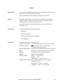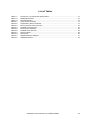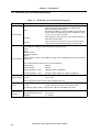
1
User’s Manual PG-FA-S/F_Line Flash Programming Adapter for S_Line and F_Line Microcontroller Devices Document No. U17213EE1V0UM00 Date Published August 2004 NEC Corporation 2004 Printed in Germany NEC Corporation 2004 This equipment complies with the EMC protection requirements WARNING This is a ‘Class A’ (EN 55022: 1998) equipment. This equipment can cause radio frequency noise when used in the residential area. In such cases, the user/operator of the equipment may be required to take appropriate countermeasures under his responsibility. EEDT-ST-001-11 CAUTION This equipment should be handled like a CMOS semiconductor device. The user must take all precautions to avoid build-up of static electricity while working with this equipment. All test and measurement tool including the workbench must be grounded. The user/operator must be grounded using the wrist strap. The connectors and/or device pins should not be touched with bare hands. EEDT-ST-004-10 2 Preliminary User’s Manual U17213EE1V0UM00 • The information in this document is current as of 03.08. 2004. The information is subject to change without notice. For actual design-in, refer to the latest publications of NEC Electronics data sheets or data books, etc., for the most up-to-date specifications of NEC Electronics products. Not all products and/or types are available in every country. Please check with an NEC sales representative for availability and additional information. • No part of this document may be copied or reproduced in any form or by any means without prior written consent of NEC Electronics. NEC Electronics assumes no responsibility for any errors that may appear in this document. • NEC Electronics does not assume any liability for infringement of patents, copyrights or other intellectual property rights of third parties by or arising from the use of NEC Electronics products listed in this document or any other liability arising from the use of such NEC Electronics products. No license, express, implied or otherwise, is granted under any patents, copyrights or other intellectual property rights of NEC Electronics or others. • Descriptions of circuits, software and other related information in this document are provided for illustrative purposes in semiconductor product operation and application examples. The incorporation of these circuits, software and information in the design of customer's equipment shall be done under the full responsibility of customer. NEC Electronics no responsibility for any losses incurred by customers or third parties arising from the use of these circuits, software and information. • While NEC Electronics endeavors to enhance the quality, reliability and safety of NEC Electronics products, customers agree and acknowledge that the possibility of defects thereof cannot be eliminated entirely. To minimize risks of damage to property or injury (including death) to persons arising from defects in NEC Electronics products, customers must incorporate sufficient safety measures in their design, such as redundancy, fire-containment and anti-failure features. • NEC Electronics products are classified into the following three quality grades: “Standard”, “Special” and “Specific”. The "Specific" quality grade applies only to NEC Electronics products developed based on a customerdesignated “quality assurance program” for a specific application. The recommended applications of NEC Electronics product depend on its quality grade, as indicated below. Customers must check the quality grade of each NEC Electronics product before using it in a particular application. "Standard": Computers, office equipment, communications equipment, test and measurement equipment, audio and visual equipment, home electronic appliances, machine tools, personal electronic equipment and industrial robots. "Special": Transportation equipment (automobiles, trains, ships, etc.), traffic control systems, anti-disaster systems, anti-crime systems, safety equipment and medical equipment (not specifically designed for life support). "Specific": Aircraft, aerospace equipment, submersible repeaters, nuclear reactor control systems, life support systems and medical equipment for life support, etc. The quality grade of NEC Electronics products is “Standard” unless otherwise expressly specified in NEC Electronics data sheets or data books, etc. If customers wish to use NEC Electronics products in applications not intended by NEC Electronics, they must contact NEC Electronics sales representative in advance to determine NEC Electronics 's willingness to support a given application. Notes: 1. " NEC Electronics" as used in this statement means NEC Electronics Corporation and also includes its majority-owned subsidiaries. 2." NEC Electronics products" means any product developed or manufactured by or for NEC Electronics (as defined above). M8E 02.10 Preliminary User’s Manual U17213EE1V0UM00 3 Regional Information Some information contained in this document may vary from country to country. Before using any NEC product in your application, please contact the NEC office in your country to obtain a list of authorized representatives and distributors. They will verify: • Device availability • Ordering information • Product release schedule • Availability of related technical literature • Development environment specifications (for example, specifications for third-party tools and components, host computers, power plugs, AC supply voltages, and so forth) • Network requirements In addition, trademarks, registered trademarks, export restrictions, and other legal issues may also vary from country to country. NEC Electronics America Inc. Santa Clara, California Tel: 408-588-6000 800-366-9782 Fax: 408-588-6130 800-729-9288 NEC Electronics (Europe) GmbH Duesseldorf, Germany Tel: 0211-65 03 1101 Fax: 0211-65 03 1327 Sucursal en España Madrid, Spain Tel: 091- 504 27 87 Fax: 091- 504 28 60 Succursale Française Vélizy-Villacoublay, France Tel: 01-30-67 58 00 Fax: 01-30-67 58 99 4 Filiale Italiana Milano, Italy Tel: 02-66 75 41 Fax: 02-66 75 42 99 NEC Electronics Hong Kong Ltd. Hong Kong Tel: 2886-9318 Fax: 2886-9022/9044 Branch The Netherlands Eindhoven, The Netherlands Tel: 040-244 58 45 Fax: 040-244 45 80 NEC Electronics Hong Kong Ltd. Seoul Branch Seoul, Korea Tel: 02-528-0303 Fax: 02-528-4411 Branch Sweden Taeby, Sweden Tel: 08-63 80 820 Fax: 08-63 80 388 United Kingdom Branch Milton Keynes, UK Tel: 01908-691-133 Fax: 01908-670-290 NEC Electronics Singapore Pte. Ltd. Singapore Tel: 65-6253-8311 Fax: 65-6250-3583 NEC Electronics Taiwan Ltd. Taipei, Taiwan Tel: 02-2719-2377 Fax: 02-2719-5951 Preliminary User’s Manual U17213EE1V0UM00 Preface Target Reader This manual is intended for users who want to understand the functions of the PG-FA-S/F_Line flash programming adapter. Basic understanding of microcontroller environment is assumed. Purpose By using the PG-FA-S/F_Line, program code can easily be erased from, verified or written to the flash memory of an NEC on-chip flash memory microcontroller mounted on the PG-FA-S/F_Line. This manual explains the basic specifications and correct usage of the PG-FA-S/F_Line. Organization Conventions This manual includes the following chapters: • Introduction • Hardware description • Supported devices and mount adapters • Circuit diagrams Symbols and notation are used as follows: Weight in data notation : Left is high-order column, right is low order column Active low notation : xxx (pin or signal name is over-scored) or /xxx (slash before signal name) Memory map address: : High order at high stage and low order at low stage Note : Footnote for an item marked with Note in the text Caution : Information requiring particular attention Remark : Supplementary explanation Numeric notation : Binary . . . XXXX or XXXB Decimal . . . XXXX Hexadecimal . . . XXXXH or 0x XXXX Prefixes representing powers of 2 (address space, memory capacity) K (kilo): 210 = 1024 M (mega): 220 = 10242 = 1,048,576 G (giga): 230 = 10243 = 1,073,741,824 Preliminary User’s Manual U17213EE1V0UM00 5 [MEMO] 6 Preliminary User’s Manual U17213EE1V0UM00 Table of Contents Preface . . . . . . . . . . . . . . . . . . . . . . . . . . . . . . . . . . . . . . . . . . . . . . . . . . . . . . . 5 Chapter 1 1.1 1.2 1.3 1.4 1.5 1.6 Chapter 2 2.1 2.2 2.3 2.4 2.5 2.6 2.7 Introduction. . . . . . . . . . . . . . . . . . . . . . . . . . . . . . . . . . . . . . . . . . . . . . . . . . . 13 Main Features of the PG-FA-S/F_Line . . . . . . . . . . . . . . . . . . . . . . . . . . . . . . . . . . . . . 13 Package Content . . . . . . . . . . . . . . . . . . . . . . . . . . . . . . . . . . . . . . . . . . . . . . . . . . . . . . 13 PG-FA-S/F_Line Functional Specification . . . . . . . . . . . . . . . . . . . . . . . . . . . . . . . . . . 14 System Requirements . . . . . . . . . . . . . . . . . . . . . . . . . . . . . . . . . . . . . . . . . . . . . . . . . . 15 Related Documents . . . . . . . . . . . . . . . . . . . . . . . . . . . . . . . . . . . . . . . . . . . . . . . . . . . . 15 Document History . . . . . . . . . . . . . . . . . . . . . . . . . . . . . . . . . . . . . . . . . . . . . . . . . . . . . 15 Hardware Description . . . . . . . . . . . . . . . . . . . . . . . . . . . . . . . . . . . . . . . . . . 17 Host Interfaces / Programming Sources . . . . . . . . . . . . . . . . . . . . . . . . . . . . . . . . . . . 17 2.1.1 USB Host Connector . . . . . . . . . . . . . . . . . . . . . . . . . . . . . . . . . . . . . . . . . . . . . 18 2.1.2 PG-FP4 Connector . . . . . . . . . . . . . . . . . . . . . . . . . . . . . . . . . . . . . . . . . . . . . . . 18 2.1.3 UART Host Connector . . . . . . . . . . . . . . . . . . . . . . . . . . . . . . . . . . . . . . . . . . . . 19 2.1.4 Null Modem Cable . . . . . . . . . . . . . . . . . . . . . . . . . . . . . . . . . . . . . . . . . . . . . . . 20 Power Supply . . . . . . . . . . . . . . . . . . . . . . . . . . . . . . . . . . . . . . . . . . . . . . . . . . . . . . . . . 21 2.2.1 External power connectors . . . . . . . . . . . . . . . . . . . . . . . . . . . . . . . . . . . . . . . . . 21 CREG socket . . . . . . . . . . . . . . . . . . . . . . . . . . . . . . . . . . . . . . . . . . . . . . . . . . . . . . . . . 22 Clock Sources . . . . . . . . . . . . . . . . . . . . . . . . . . . . . . . . . . . . . . . . . . . . . . . . . . . . . . . . 22 2.4.1 Oscillator socket . . . . . . . . . . . . . . . . . . . . . . . . . . . . . . . . . . . . . . . . . . . . . . . . . 24 2.4.2 Crystal / resonator socket . . . . . . . . . . . . . . . . . . . . . . . . . . . . . . . . . . . . . . . . . . 25 Device Sockets (for Mount Adapters) . . . . . . . . . . . . . . . . . . . . . . . . . . . . . . . . . . . . . 26 2.5.1 Device socket for V850ES/FE2 (64-pin) . . . . . . . . . . . . . . . . . . . . . . . . . . . . . . . 26 2.5.2 Device socket for V850ES/FF2 (80-pin) . . . . . . . . . . . . . . . . . . . . . . . . . . . . . . . 26 2.5.3 Device socket for V850ES/SG2 and V850ES/FG2 (100-pin, square) . . . . . . . . 27 2.5.4 Device socket for V850ES/SG2 (100-pin, rectangular) . . . . . . . . . . . . . . . . . . . 28 2.5.5 Device socket for V850ES/SJ2 and V850ES/FJ2 (144-pin) . . . . . . . . . . . . . . . . 28 Reset Button. . . . . . . . . . . . . . . . . . . . . . . . . . . . . . . . . . . . . . . . . . . . . . . . . . . . . . . . . . 29 LEDs . . . . . . . . . . . . . . . . . . . . . . . . . . . . . . . . . . . . . . . . . . . . . . . . . . . . . . . . . . . . . . . . 30 2.7.1 VDD power LED . . . . . . . . . . . . . . . . . . . . . . . . . . . . . . . . . . . . . . . . . . . . . . . . . 30 2.7.2 USB power LED . . . . . . . . . . . . . . . . . . . . . . . . . . . . . . . . . . . . . . . . . . . . . . . . . 30 2.7.3 USB activity LED . . . . . . . . . . . . . . . . . . . . . . . . . . . . . . . . . . . . . . . . . . . . . . . . 30 Chapter 3 Supported Devices and Mount Adapters . . . . . . . . . . . . . . . . . . . . . . . . . . . 31 Chapter 4 Circuit Diagrams. . . . . . . . . . . . . . . . . . . . . . . . . . . . . . . . . . . . . . . . . . . . . . . 33 Preliminary User’s Manual U17172EE1V0UM00 7 8 Preliminary User’s Manual U17172EE1V0UM00 List of Figures Figure 2-1: Figure 2-2: Figure 4-1: Figure 4-2: Figure 4-3: Figure 4-4: Figure 4-5: Figure 4-6: Pinout of the UART Connector (Sub-D 9-pin male)..................................................... 20 Connection Diagram of the Supplied Null-Modem Cable ............................................ 20 Power / Clock .............................................................................................................. 33 PG-FP4 Connector / UART /nWire.............................................................................. 34 USB-UART Converter ................................................................................................. 35 Socket Bases 64 / 80 .................................................................................................. 36 Socket Bases 100 / 144 .............................................................................................. 37 Socket Bases 100GF .................................................................................................. 38 Preliminary User’s Manual U17172EE1V0UM00 9 10 Preliminary User’s Manual U17172EE1V0UM00 List of Tables Table 1-1: Table 1-2: Table 1-3: Table 2-1: Table 2-2: Table 2-3: Table 2-4: Table 2-5: Table 2-6: Table 2-7: Table 2-8: Table 3-1: Table 3-2: PG-FA-S/F_Line Functional Specifications .................................................................... 14 Related Documents ........................................................................................................ 15 Document History ........................................................................................................... 15 Components Functions................................................................................................... 17 Programming Source Priorities....................................................................................... 17 Pinout of the PG-FP4 Connector.................................................................................... 19 Possible Power Sources................................................................................................. 21 Clock Source Selection .................................................................................................. 22 Possible Clock Sources.................................................................................................. 23 Clock Priorities................................................................................................................ 23 SO2 Pinout .................................................................................................................... 25 Supported Mount Adapters............................................................................................. 31 Supported Devices ......................................................................................................... 32 Preliminary User’s Manual U17172EE1V0UM00 11 12 Preliminary User’s Manual U17172EE1V0UM00 Chapter 1 Introduction The PG-FA-S/F_Line is a flash programmer and programming adapter for all NEC microcontrollers of the S_Line and F_Line. PG-FA-S/F_Line is designed for three types of operation: It can be used as a USB programmer, it can be used as a UART programmer and it can be used as a programming adapter in combination with a PG-FP4. 1.1 Main Features of the PG-FA-S/F_Line • Can program any flash device of the S_Line and F_Line microcontroller series (see Table 3-2 on page 32 for a list of supported devices). • Can be used with FPL software GUI, available on the internet (see the “Serial Flash Writer” section on http://www.ee.nec.de/update). • USB operation: A device can be programmed using a host PC connected to the PG-FA-S/ F_Line using a USB cable. No extra hardware is required. • RS232 operation: A device can be programmed using a host PC connected to the PG-FA-S/ F_Line using a null-modem cable (VDD must be supplied externally). • PG-FP4 operation: A device can be programmed using a PG-FP4 connected to the PG-FA-S/ F_Line. • Self programming operation: The PG-FA-S/F_Line can be used as a minimal target system to check self programming operation (no support). • Selectable VDD source: For USB operation and for PG-FP4 operation the VDD can be supplied from the host, or optionally externally. • Selectable clock source: Either an on-board crystal or an on-board oscillator can be used as a clock source. When using PG-FA-S/F_Line in combination with a PG-FP4, the PG-FP4 can be used as the clock source. • Exchangeable CREG: in case a different value should be used for the on-chip regulators external capacity, it can be placed in a socket. Note: This product is intended for development and evaluation purposes only. It is not intended to be used in mass production. 1.2 Package Content After opening the package of the PG-FA-S/F_Line, please first check the content of the box. It should contain the following: • 1 pcs PG-FA-S/F_Line PCB • 1 pcs crystal module 5MHz (assembled on the PCB) • 1 pcs USB cable (A-B type) • 1 pcs RS232 null modem cable (see Figure 2-2, “Connection Diagram of the Supplied NullModem Cable,” on page 20) • ReadMe booklet Preliminary User’s Manual U17213EE1V0UM00 13 Chapter 1 Introduction 1.3 PG-FA-S/F_Line Functional Specification Table 1-1: PG-FA-S/F_Line Functional Specifications Item Specification USB USB type ‘B’ connector. USB conforms to USB rev. 1.1. Note: USB is only supported on Windows 98, Windows ME, Windows 2000 and Windows XP. Note that the USB port is used to emulate a virtual COM port only as USB is not supported by the FPL software nor by the S_Line or F_Line micro controllers. RS-232C Sub-D type 9-pin male connector. Communication speed corresponds to device speed. PG-PF4 16 pin connector (2 x 8 x 2.54 mm). This connector can be used with the standard PG-FP4 target connection cable. Host interfaces Device interface The devices must be enclosed in a mount adapter (not included in this package). Five socket receptables are available for the following device package types: 64-pin 80-pin 100-pin (square) 100-pin (rectangular) 144-pin Refer to Table 3-1 (page 31) and Table 3-2 (page 32) for a detailed list of devices and sockets supported. The communications interface can be one of the following: Supply voltage USB operation: UARTA0 UART operation: UARTA0 PG-FP4 operation, S_Line: UARTA0, CSIB0 or CSIB0+HS PG-FP4 operation, F_Line: UARTA0, CSIB0, CSIB0+HS, CSIB3 or CSIB3+HS S_Line 2.85 V to 3.6 V F_Line 3.5 V to 5.5 V When supplied by USB, the device will be supplied with 3.55V Clock S_Line 2.5 MHz to 10 MHz (ext.), see S_Line User’s Manual F_Line 4 MHz to 5 MHz (ext.), see F_Line User’s Manual By default a crystal module or resonator with 5 MHz is assembled on the PCB. Environmental conditions 14 Operating temperature range: 0°C to 40°C Storage temperature range: -15°C to 60°C Humidity: 10 - 80%RH Preliminary User’s Manual U17213EE1V0UM00 Chapter 1 Introduction 1.4 System Requirements To operate the PG-FA-S/F_Line in USB mode, a host PC with a free USB port is required. This host PC must be running the FPL software. The operating system must support USB. Optionally an external power supply can be used. To operate the PG-FA-S/F_Line in UART mode, a host PC with a free COM port is required. This host PC must be running the FPL software. An external power supply must be used. To operate the PG-FA-S/F_Line in combination with a PG-FP4, a PG-FP4 is required. Optionally an external power supply can be used. 1.5 Related Documents These related documents may contain helpful information and will help for a better general understanding. Table 1-2: Related Documents Document Name Document No. User’s Manual FPL, Serial Flash Writer WEB-00024427 User’s Manual PG-FP4, Flash Programmer U15260EE2V0UM00 All device User’s Manuals of all S_Line and F_Line microcontrollers Consult the internet documentation database and use the keywords S_Line and F_Line for searching 1.6 Document History Table 1-3: Document History Date Revision Chapter Description July 2004 V1.0 All Initial release Preliminary User’s Manual U17213EE1V0UM00 15 [MEMO] 16 Preliminary User’s Manual U17213EE1V0UM00 Chapter 2 Hardware Description Table 2-1: Components Functions Component Function CN1 VDD CN2 GND CN3 PG-FP4 CN4 UART CN5 Reserved CN6 USB CN7-CN17 Device sockets SO1 CREG SO2 Crystal / resonator SO3 Oscillator SW1 Reset JP1 Clock source JP2 Reserved JP3 Reserved D3 (red) LED USB activity D4 (green) LED USB power D6 (green) LED VDD 2.1 Host Interfaces / Programming Sources It is mechanically possible to connect the adapter to more than one programming source simultaneously. In this case the sources have different priorities: Table 2-2: Programming Source Priorities Priority Programming source Highest USB Medium PG-FP4 Lowest UART Note: When trying to program from multiple sources simultaneously programming may fail. However no harm to the device or the flash adapter should occur. Preliminary User’s Manual U17213EE1V0UM00 17 Chapter 2 Hardware Description 2.1.1 USB Host Connector The USB connection to the host PC is established by CN6 located at the left side of the PG-FA-S/ F_Line. Note: This connection is hot-pluggable. CN6 USB PG-FA-S/F_Line 2.1.2 PG-FP4 Connector The connection to a PG-PF4 is established by CN3 located at the left side of the PG-FA-S/F_Line. CN3 PG-FP4 PG-FA-S/F_Line 18 Preliminary User’s Manual U17213EE1V0UM00 Chapter 2 Table 2-3: Hardware Description Pinout of the PG-FP4 Connector GND 1 2 RESET SI / RXD 3 4 VDD SO / TXD 5 6 VPP (n.c.) SCK 7 8 H/S CLK 9 10 VDE (n.c.) VDD2 (n.c.) 11 12 FLMD1 n.c. 13 14 FLMD0 n.c. 15 16 n.c. Note: all signals have VDD level 2.1.3 UART Host Connector The UART connection to the host PC is established by CN4 located at the left side of the PG-FA-S/F_Line. CN4 UART PG-FA-S/F_Line Preliminary User’s Manual U17213EE1V0UM00 19 Chapter 2 Figure 2-1: Hardware Description Pinout of the UART Connector (Sub-D 9-pin male) 1 DCD Loop to DTR and DSR 2 RXD Connects to RXD of microcontroller 3 TXD Connects to TXD of microcontroller 4 DTR Loop to DCD and DSR 5 GND 6 DSR Loop to DCD and DTR 7 RTS Loop to CTS 8 CTS Loop to RTS Can be used for RESET 9 RI Static L 1 6 5 9 Note: all signals have RS-232 levels 2.1.4 Null Modem Cable The host cable is a standard shielded RS-232 cable of 2 to 3 meters length. The connectors on both sides are Sub-D 9-pin female. The cable used must have the lines RXD/TXD and RTS/CTS crossed (for normal operation with a standard PC). Figure 2-2: DCD RXD TXD DTR GND DSR RTS CTS RI 20 Connection Diagram of the Supplied Null-Modem Cable 1 2 3 4 5 6 7 8 9 1 2 3 4 5 6 7 8 9 Preliminary User’s Manual U17213EE1V0UM00 DCD RXD TXD DTR GND DSR RTS CTS RI Chapter 2 Hardware Description 2.2 Power Supply The microcontroller can be supplied by an external power supply, by USB bus power or by the PG-FP4. Table 2-4: Possible Power Sources Power source Programming source External power supply USB PG-FP4 PG-FP4 Yes No Yes UART Yes No No USB YesNote Yes No Note: When supplying from two sources at the same time programming may fail. However no harm to the device or the flash adapter should occur. 2.2.1 External power connectors If the microcontroller should be supplied externally, VDD can be applied to CN1 and CN2 located at the left side of the PG-FA-S/F_Line. CN1 (red, left): CN2 (black, right): VDD GND Note: When the USB port is connected, it supplies the microcontroller with 3.55 V. You should not connect a lower voltage than 3.55 V to the power connectors if USB is used. A higher voltage than 3.55 V may be applied. The microcontroller is then supplied by the power connectors and not by USB. Caution: The applied voltage is connected directly to the microcontroller, so be sure that it does not exceed the limits of the device (max. 5.5 V for F_Line; max. 3.6 V for S_Line). CN1 VDD CN2 GND PG-FA-S/F_Line Preliminary User’s Manual U17213EE1V0UM00 21 Chapter 2 Hardware Description 2.3 CREG socket The internal voltage regulator of the microcontroller device requires an external capacity. This capacity is assembled in socket SO1 and usually has a value of 4.7 µF. Refer to the microcontroller User’s Manual for more details. REGC pin of microcontroller GND 21 Pin1 (top): Pin2 (bottom): SO1 CREG PG-FA-S/F_Line 2.4 Clock Sources A crystal, a resonator or an oscillator (supplied by VDD) can be mounted onto a socket. The clock usually has 5 MHz. The frequency depends on the assembled microcontroller device and its programming mode (usually 2.5 MHz to 5 MHz). If the UART or USB interface is used for programming, mounting a crystal, resonator or oscillator is mandatory. A jumper selects the source of the clock: on-board crystal or external clock from PG-FP4 or oscillator. Table 2-5: Clock Source Selection JP1 22 Clock source Open (default) Crystal, resonator or PG-FP4 Closed Oscillator Preliminary User’s Manual U17213EE1V0UM00 Chapter 2 Table 2-6: Hardware Description Possible Clock Sources Clock source Programming source Crystal or resonator Oscillator PG-FP4 PG-FP4 Yes Yes Yes UART Yes Yes No USB Yes Yes No Table 2-7: Priority Clock Priorities Clock source Highest PG-FP4 Medium Oscillator Lowest Crystal or resonator Note: When choosing an incorrect clock source or supplying multiple clocks simultaneously programming may fail. However no harm to the device or the flash adapter should occur. Preliminary User’s Manual U17213EE1V0UM00 23 Chapter 2 Hardware Description 2.4.1 Oscillator socket If the an oscillator should be used as the clock source for the microcontroller device, it must be assembled in SO3. For this clock source jumper JP1 must be closed. DIL14 and DIL8-type oscillators can be assembled. When assembling DIL8-type oscillators align pin 1 of the oscillator with pin 1 of the socket. Notes: 1. The oscillator is supplied by VDD (range: 2.85 V to 5.5 V), so be sure it supports this voltage. 2. Pin 1 has a pull-up of 4.7 K to VDD in case oscillators with /OE on pin 1 are used. SO3 Oscillator JP1 closed PG-FA-S/F_Line 24 Preliminary User’s Manual U17213EE1V0UM00 Chapter 2 Hardware Description 2.4.2 Crystal / resonator socket If a crystal or a resonator should be used as the clock source for the microcontroller device, it must be assembled in SO2. For this clock source jumper JP1 must be open. JP1 open 1 SO2 Crystal / resonator PG-FA-S/F_Line Pin 1 2 3 4 5 6 7 Table 2-8: SO2 Pinout Signal GND X1 X1 GND X2 X2 GND Intended usage Resonator Preliminary User’s Manual U17213EE1V0UM00 25 Chapter 2 Hardware Description 2.5 Device Sockets (for Mount Adapters) The microcontrollers that are to be programmed must be enclosed in a mount adapter and then placed on one of the five foreseen spots on the PG-FA-S/F_Line. Cautions: 1. Do not place or remove a mount adapter while the board is powered. This may damage the microcontroller device. 2. Never mount more than one mount adapter at the same time. This may damage the microcontroller devices. 2.5.1 Device socket for V850ES/FE2 (64-pin) V850ES/FE2 64-pin GB CN7/CN8 PG-FA-S/F_Line 2.5.2 Device socket for V850ES/FF2 (80-pin) V850ES/FF2 80-pin GK CN9/CN10 PG-FA-S/F_Line 26 Preliminary User’s Manual U17213EE1V0UM00 Chapter 2 Hardware Description 2.5.3 Device socket for V850ES/SG2 and V850ES/FG2 (100-pin, square) V850ES/SG2 V850ES/FG2 100-pin GC CN11/CN12 PG-FA-S/F_Line Caution: The receptables for the 100-pin square and 100-pin rectangular mount adapters have the same appearance and geometry. It is physically possible to place the mount adapter into the wrong receptable. This can damage the microcontroller or the PF-FA-S/F_Line. A mechanical blocking (TP1) should prevent a 100-pin rectangular mount adapter to be placed into the 100-pin square receptable. But it is possible to place a 100-pin square mount adapter into the 100-pin rectangular receptable. Please take care not to mix up the receptables. Preliminary User’s Manual U17213EE1V0UM00 27 Chapter 2 Hardware Description 2.5.4 Device socket for V850ES/SG2 (100-pin, rectangular) PG-FA-S/F_Line V850ES/SG2 100-pin GF CN16/CN17 Caution: The receptables for the 100-pin square and 100-pin rectangular mount adapters have the same appearance and geometry. It is physically possible to place the mount adapter into the wrong receptable. This can damage the microcontroller or the PF-FA-S/F_Line. A mechanical blocking (TP1) should prevent a 100-pin rectangular mount adapter to be placed into the 100-pin square receptable. But it is possible to place a 100-pin square mount adapter into the 100-pin rectangular receptable. Please take care not to mix up the receptables. 2.5.5 Device socket for V850ES/SJ2 and V850ES/FJ2 (144-pin) V850ES/SJ2 V850ES/FJ2 144-pin GJ CN13/CN14/CN15 PG-FA-S/F_Line 28 Preliminary User’s Manual U17213EE1V0UM00 Chapter 2 Hardware Description 2.6 Reset Button The microcontroller device can be reset by pressing the reset button. Depending on the setting of the Serial Writer software, this might be necessary during programming. Usually, however, this is not necessary. SW1 Reset PG-FA-S/F_Line Preliminary User’s Manual U17213EE1V0UM00 29 Chapter 2 Hardware Description 2.7 LEDs D6 (green) V DD (red) D3 D4 (green) USB USB activity power PG-FA-S/F_Line 2.7.1 VDD power LED This green LED lights when VDD is present at the microcontroller. It lights when any power supply is attached (PG-FP4, USB and ext. power supply). 2.7.2 USB power LED This green LED lights when the USB port is connected and powered. 2.7.3 USB activity LED This red LED will light when there is activity (send or receive) on the USB bus. 30 Preliminary User’s Manual U17213EE1V0UM00 Chapter 3 Supported Devices and Mount Adapters Table 3-1: Supported Mount Adapters S-Line F-Line 64-pin GB - QB-64GB-MA-01S (QB-V850ESFX2-S64GB) 80-pin GC - QB-80GK-MA-01S (QB-V850ESFX2-S80GK) 100-pin GC QB-100GF-MA-01S (QB-V850ESSX2-S100GC) 100-pin GF QB-100GF-MA-01S (QB-V850ESSX2-S100GF) 144-pin GJ QB-144GJ-MA-01S (QB-V850ESSX2-S144GJ) QB-100GC-MA-01S (QB-V850ESFX2-S100GC) QB-144GJ-MA-01S (QB-V850ESFX2-S144GJ) Preliminary User’s Manual U17213EE1V0UM00 31 Chapter 3 Supported Devices and Mount Adapters Table 3-2: Supported Devices S-Line 64-pin GB 80-pin GC - µPD3231MXGB(A)-YEN µPD3231MXGB(A1)-YEN - µPD3232MXGK(A)-9EU µPD3232MXGK(A1)-9EU µPD3233MXGK(A)-9EU µPD3233MXGK(A1)-9EU 100-pin GC µPD70F3261GC-8EU µPD70F3261YGC-8EU µPD70F3263GC-8EU µPD70F3263YGC-8EU µPD70F3281GC-8EU µPD70F3281YGC-8EU µPD70F3281GC-8EU µPD70F3281YGC-8EU 100-pin GF µPD70F3261GF-JBT µPD70F3261YGF-JBT µPD70F3263GF-JBT µPD70F3263YGF-JBT µPD70F3281GF-JBT µPD70F3281YGF-JBT µPD70F3281GF-JBT µPD70F3281YGF-JBT 144-pin GJ µPD70F3264GJ-UEN µPD70F3264YGJ-UEN µPD70F3266GJ-UEN µPD70F3266YGJ-UEN µPD70F3284GJ-UEN µPD70F3284YGJ-UEN µPD70F3286GJ-UEN µPD70F3286YGJ-UEN µPD70F3288GJ-UEN µPD70F3288YGJ-UEN 32 F-Line µPD3234MXGC(A)-8EA µPD3234MXGC(A1)-8EA µPD3235MXGC(A)-8EA µPD3235MXGC(A1)-8EA µPD3236MXGC(A)-8EA µPD3236MXGC(A1)-8EA - µPD3237MXGJ(A)-UEN µPD3237MXGJ(A1)-UEN µPD3238MXGJ(A)-UEN uPD3238MXGJ(A1)-UEN µPD3239MXGJ(A)-UEN µPD3239MXGJ(A1)-UEN Preliminary User’s Manual U17213EE1V0UM00 Chapter 4 Circuit Diagrams Figure 4-1: VDD_EXT CN1 std_lab_socket_red 1 2 Power / Clock VDD 2.85-5.5V 1 2.85-5.5V VCCOUT SO1 1 C_reg CN2 std_lab_socket_black R1 10k 2 typ. 4.7uF TP1 TP/Ground-Testpoint 1 2 VDD 4.4-5.25V 2.5V FC1 2200pF/25VDC/6A GND 3 VDD_USB V_REGC 2 SD IC1 LP3964EMP/adj 2 3 vin vout 1 4 _sd adj gnd 5 D1 SchottkyDiode/1A/15V/10BQ015 3.55V R2 8.2k C2 10u/10V/taj_b 3-D6 C1 10u/10V/taj_b 2.85-5.5V R3 4.3K VDD 2.85-5.5V CLK 6-E1,5-E1,#3 R30 470 SO2 7pins/female Crystal socket D6 SMD-LED/green/If=10mA 1 2 3 6-E1,5-E1,#3 X1 6-E1,5-E1,4-B6 X2 4 5 6 noass 7 VDD R28 100 R29 100 2.85-5.5V V_REGC 2.5V SO3 DIL-Socket14 C3 100nf/16V/eia0603 1 2 3 4 5 6 7 Oscillator socket 14 13 12 11 10 9 8 74AHC1G126GW R5 4.7k IC2 1 oe y 4 2 a gnd vcc 3 5 C29 100nf/16V/eia0603 74AHC1G126GW IC3 1 oe y 4 2 a gnd vcc 5 3 noass R4 4.7k 1 JP1 Clock source 2 Open: crystal (default) Closed: oscillator R6 4.7k C28 100nf/16V/eia0603 Preliminary User’s Manual U17213EE1V0UM00 33 Chapter 4 Figure 4-2: Circuit Diagrams PG-FP4 Connector / UART /nWire VDD_EXT CN3 2.85-5.5V PG-FP4 connector 16pins/male/housing/rectangle SO_TXD 5 6 VPP SCK 7 8 HS 6-D1,5-D1,4-B6 CLK 9 10 VDE VDD2 11 12 FLMD1 13 14 15 16 6-D1,5-D1,#3 FLMD0 6-D1,5-D1,#2 6-E1,5-E1,#2 6-D1,5-D1,#3 6-D1,5-D1,#3 6 gnd2 SCK SO_TXD SI_RXD 2 6-D1,5-D1,#2 FLMD1 R8 4.7k R34 4.7k C5 1u/25V/taj_a C8 C7 1u/25V/taj_a 13 VL 20 VCC 2 Vplus 6 Vminus 18 GND RTS TXD 17 CTS 16 RXD 15 10 CTS 14 11 7 C1plus C1minus C2plus C2minus T1out_RS232 T1in_TTL T2out_RS232 T2in_TTL R1in_RS232 R2in_RS232 invalid_z 2.85-5.5V nWire b1 19 force_off_z 12 force_on 8 RI FLMD0 R31 470 CLK 7 9 gnd1 DSR Open: PGM (default) Closed: nWire 6-D1,5-D1,#2 R1out_TTL R2out_TTL 1 C6 220nf/63V/eia0805 C4 SW1 Reset OMRON/B3S-1000P CN5 noass a1 VDD b2 a2 b3 a3 b4 a4 b5 a5 b6 a6 b7 a7 6-E1,5-E1,4-B6 DDI b8 a8 6-E1,5-E1,4-B6 DCK b9 2.85-5.5V 3 4 C9 1u/25V/taj_a 5 R10 2.2k 8 9 R11 2.2k 11 6-D1,5-D1,#3 6-D1,5-D1,#3 SI_RXD SO_TXD 10 1 oe 2 a gnd 3 IC10 74AHC1G126GW R12 2.2k 6-D1,5-D1,#3 y 4 vcc VDD 5 2.85-5.5V RESET R13 4.7k R14 4.7k R15 4.7k a9 6-E1,5-E1,4-B6 DMS b10 a10 6-E1,5-E1,4-B6 DDO b11 a11 6-E1,5-E1,4-B6 DRST b12 a12 b13 a13 C38 100nf/16V/eia0603 34 RESET noass DTR FLMD0 1 IC4 MAX3380ECPU/2_35to5_5V/Shutdown 2.85-5.5V TXD 5 noass noass 4 JP2 FLMD1 noass 3 R9 10k Preliminary User’s Manual U17213EE1V0UM00 6-D1,5-D1,#2 noass RXD R7 4.7k HS VDD 220nf/63V/eia0805 2 2.85-5.5V VDD CN4 UART 9pins/rectangle/male DCD VDD 2.85-5.5V 6-D1,5-D1,#3 6-D1,5-D1,#2 6-D1,5-D1,4-B6 1 VDD RESET 2 1 VDD_EXT 4 3 RESET 4 100nf/16V/eia0603 2 3 noass 1 SI_RXD R16 10k FLMD0 Chapter 4 Figure 4-3: Circuit Diagrams USB-UART Converter VDD_USB 4.4-5.25V VDD_USB L1 40nH/560mA R33 27 VDD_USB 4.4-5.25V 4.4-5.25V R19 470 R25 10k C10 10nf/50V/eia0603 C13 100nf/16V/eia0603 C14 100nf/16V/eia0603 1 JP3 2 Reserved Default: open noass C15 100nf/16V/eia0603 R26 4.7k C11 27pf/50V/eia0603 6-D1,5-D1,#2 SI_RXD 6-D1,5-D1,#2 SO_TXD 6-D1,5-D1,#2 RESET IC8 1 74AHC1G126GW oe 2 a y 4 gnd vcc 3 5 X1 6.000MHz/CRYSTAL/SMD VDD 32 31 30 29 28 27 26 25 2.85-5.5V C16 RXD RTS_Z CTS_Z DTR_Z DSR_Z DCD_Z RI_Z GND2 IC9 1 74AHC1G126GW oe 24 23 22 21 20 19 18 17 2 a y 4 gnd vcc 3 5 VDD R32 4.7k 2.85-5.5V VDD_USB IC7 1 S 2 C 3 D 4 Q R27 2.2k C32 100nf/16V/eia0603 C17 100nf/16V/eia0603 R21 2.2k R22 10k VDD 2.85-5.5V GND1 SLEEP_Z RXLED_Z TXLED_Z VCCIO PWRCTL PWREN_Z TXDEN R18 27 IC5 FTDI/FT232BM 4.4-5.25V VDD_USB 4.4-5.25V 1 oe IC6 74AHC1G126GW 2 a y 4 gnd vcc 3 5 1-B5 VDD_USB 4.4-5.25V SD C34 10nf/50V/eia0603 C33 100nf/16V/eia0603 noass R23 470 R24 470 noass VCC DU ORG VSS 8 7 6 5 noass 5 33nf/25V/eia0603 6 EESK EEDATA VCC1 RESET_Z RESETO_Z 3V3OUT USBDP USBDM noass gnd2 gnd1 R20 1.5k R17 27 1 2 3 4 5 6 7 8 9 10 11 12 13 14 15 16 CN6 4pins/USB 1 vnet 2 dm 3 dp 4 gndnet C31 100nf/16V/eia0603 EECS TEST AVCC AGND XTout XTin VCC2 TXD C12 27pf/50V/eia0603 C30 100nf/16V/eia0603 D3 SMD-LED/red/If=10mA D4 SMD-LED/green/If=10mA FM93C46LEM8/2.7-5.5V Preliminary User’s Manual U17213EE1V0UM00 35 Figure 4-4: Socket Bases 64 / 80 V850ES/FF2 (80GK) V850ES/FE2 (64GB) 39 37 35 33 31 29 27 25 23 21 19 17 15 13 11 9 7 5 3 1 64 2 16 17 61 56 62 57 63 58 64 59 65 60 66 55 67 54 68 53 69 52 70 51 71 10 72 9 73 8 74 7 75 6 76 1 77 2 78 3 79 4 80 5 40 38 36 34 32 30 28 26 24 22 20 18 16 14 12 10 8 6 4 2 C19 100nf/16V/eia0603 1 1 VDD V_REGC 2.85-5.5V SCK SO_TXD SI_RXD HS 6-D1,5-D1,2-B3 6-D1,5-D1,#2 6-D1,5-D1,#2 6-D1,5-D1,2-B3 RESET 6-D1,5-D1,#2 FLMD0 FLMD1 6-D1,5-D1,#1 X1 X2 6-E1,5-E1,#2 DRST DMS DCK DDI DDO 36 2.5V 6-D1,5-D1,#1 6-E1,5-E1,1-D4 6-E1,5-E1,2-E6 6-E1,5-E1,2-D6 6-E1,5-E1,2-D6 6-E1,5-E1,2-D6 6-E1,5-E1,2-E6 Preliminary User’s Manual U17213EE1V0UM00 CN9 40pins/AXK/Socket 39 37 35 33 31 29 C20 27 100nf/16V/eia0603 25 23 21 19 17 15 13 11 9 7 5 3 1 45 40 44 39 43 38 42 37 41 36 46 35 47 34 48 33 49 32 50 31 11 30 12 29 13 28 14 27 15 26 20 25 19 24 18 23 17 22 16 21 40 38 36 34 32 30 28 26 24 22 20 18 16 14 12 10 8 6 4 2 C21 100nf/16V/eia0603 CN10 40pins/AXK/Header CN8 CN7 C18 34pins/AXK/Header 34pins/AXK/Socket 100nf/16V/eia0603 33 33 6/32 34 33 49 34 48 31 50 32 31 32 47 34 31 29 51 30 29 35 30 46 30 27 52 28 27 36 28 29 45 25 37 26 25 53 26 28 44 24 23 38 24 23 54 43 27 21 6/32 6/32 22 21 6/32 6/32 22 19 55 20 19 39 20 42 26 17 18 17 18 40 56 41 25 15 16 15 16 9 24 57 8 13 14 13 14 58 10 7 23 11 12 11 12 59 11 6/32 22 9 9 10 10 12 5 21 60 7 8 7 8 13 4 20 61 5 6 5 6 3 14 19 62 3 3 4 4 1 15 18 63 1 1 2 2 Chapter 4 Figure 4-5: Circuit Diagrams Socket Bases 100 / 144 V850ES/SJ2 (144GJ) V850ES/FJ2 (144GJ) V850ES/SG2 (100GC) V850ES/FG2 (100GC) CN12 50pins/AXK/Header 50 49 69 76 47 48 70 77 45 78 46 71 43 44 79 72 41 80 42 73 39 40 74 81 37 82 38 75 35 36 83 68 33 84 34 67 31 32 66 85 29 30 65 86 27 87 28 64 25 26 13 88 23 89 24 12 21 22 90 11 19 20 91 10 17 18 9 92 15 16 93 8 13 14 94 1 11 12 95 2 9 10 96 3 7 8 4 97 5 6 98 5 3 4 99 6 1 2 100 7 CN11 50pins/AXK/Socket 50 49 57 50 47 48 C22 49 56 100nf/16V/eia0603 45 46 48 55 43 44 47 54 41 53 42 46 39 40 52 45 37 51 38 44 35 36 43 58 33 59 34 42 31 32 60 41 29 30 61 40 27 62 28 39 25 26 38 63 23 14 24 37 22 21 15 36 19 20 16 35 17 18 17 34 15 16 33 18 13 14 32 25 11 12 31 24 10 9 23 30 7 8 29 22 6 5 21 28 3 4 20 27 1 2 19 26 C23 100nf/16V/eia0603 C24 100nf/16V/eia0603 CN15 50pins/AXK/Header 49 114 103 50 47 115 104 48 45 116 105 46 43 117 108 44 41 118 106 42 39 119 107 40 37 120 109 38 35 121 110 36 33 122 111 34 31 123 112 32 29 124 113 30 27 125 127 28 25 126 128 26 23 nc 24 nc 21 22 139 nc 20 19 140 129 17 18 130 141 15 16 131 142 13 14 143 132 11 12 144 133 9 10 2 134 7 8 135 4 5 6 136 3 3 4 137 5 1 2 138 1 CN14 50pins/AXK/Socket C25 100nf/16V/eia0603 49 50 94 86 47 93 48 87 45 95 46 85 43 96 44 84 41 97 42 83 39 98 40 82 37 99 38 81 35 100 36 80 33 101 34 79 C26 31 102 32 88 100nf/16V/eia0603 29 30 89 92 27 91 28 90 25 18 26 19 23 17 24 20 21 22 nc 16 19 20 15 30 17 18 14 29 15 16 6 28 13 14 7 27 11 12 8 26 10 9 9 25 7 8 24 10 5 6 11 23 3 4 13 21 1 2 1 12 22 CN13 50pins/AXK/Socket 49 73 50 66 47 48 65 77 45 78 46 64 43 44 63 75 41 42 76 62 39 74 40 61 37 72 38 60 35 71 36 59 33 34 58 70 31 32 57 69 29 68 30 56 27 67 28 55 25 nc 26 54 23 nc 24 53 21 22 52 41 20 19 51 40 17 18 39 50 15 16 38 49 13 14 48 37 11 12 47 35 9 10 34 46 7 8 36 45 5 6 33 44 3 4 32 43 1 2 31 42 C27 100nf/16V/eia0603 1 VDD V_REGC 2.85-5.5V SCK SO_TXD SI_RXD HS 6-D1,4-B6,2-B3 6-D1,4-B6,#2 6-D1,4-B6,#2 6-D1,4-B6,2-B3 RESET 6-D1,4-B6,#2 FLMD0 FLMD1 6-D1,4-B6,#1 X1 X2 6-E1,4-B6,#2 DRST DMS DCK DDI DDO 2.5V 6-D1,4-B6,#1 6-E1,4-B6,1-D4 6-E1,4-B6,2-E6 6-E1,4-B6,2-D6 6-E1,4-B6,2-D6 6-E1,4-B6,2-D6 6-E1,4-B6,2-E6 Preliminary User’s Manual U17213EE1V0UM00 37 Chapter 4 Figure 4-6: Circuit Diagrams Socket Bases 100GF V850ES/SG2 (100GF) CN17 50pins/AXK/Header 49 76 50 69 C35 47 48 70 77 45 46 100nf/16V/eia0603 43 41 39 37 35 33 31 29 27 25 23 21 19 17 15 13 11 9 7 5 3 1 78 71 79 72 80 73 81 74 82 75 83 68 84 67 85 66 86 65 87 64 88 13 89 12 90 11 91 10 92 9 93 8 94 1 95 2 96 3 97 4 98 5 99 6 100 7 44 42 40 38 36 34 32 30 28 26 24 22 20 18 16 14 12 10 8 6 4 2 CN16 50pins/AXK/Socket 49 57 50 50 47 48 56 49 45 55 46 48 44 43 54 47 41 53 42 46 39 40 52 45 37 51 38 44 35 36 58 43 34 33 59 42 31 60 32 41 29 61 30 40 27 62 28 39 25 63 26 38 24 23 14 37 21 22 36 15 19 20 35 16 17 18 34 17 15 16 33 18 13 14 32 25 11 12 31 24 9 10 30 23 8 7 22 29 5 6 21 28 3 4 20 27 1 2 19 C36 100nf/16V/eia0603 C37 100nf/16V/eia0603 26 1 VDD V_REGC 2.85-5.5V SCK SO_TXD SI_RXD HS 38 5-D1,4-B6,2-B3 5-D1,4-B6,#2 5-D1,4-B6,#2 5-D1,4-B6,2-B3 RESET 5-D1,4-B6,#2 FLMD0 FLMD1 5-D1,4-B6,#1 X1 X2 5-E1,4-B6,#2 DRST DMS DCK DDI DDO 2.5V 5-D1,4-B6,#1 5-E1,4-B6,1-D4 5-E1,4-B6,2-E6 5-E1,4-B6,2-D6 5-E1,4-B6,2-D6 5-E1,4-B6,2-D6 5-E1,4-B6,2-E6 Preliminary User’s Manual U17213EE1V0UM00 Facsimile Message From: Name Company Tel. Although NEC has taken all possible steps to ensure that the documentation supplied to our customers is complete, bug free and up-to-date, we readily accept that errors may occur. Despite all the care and precautions we've taken, you may encounter problems in the documentation. Please complete this form whenever you'd like to report errors or suggest improvements to us. FAX Address Thank you for your kind support. North America Hong Kong, Philippines, Oceania NEC Electronics America Inc. NEC Electronics Hong Kong Ltd. Corporate Communications Dept. Fax: +852-2886-9022/9044 Fax: 1-800-729-9288 1-408-588-6130 Korea Europe NEC Electronics Hong Kong Ltd. NEC Electronics (Europe) GmbH Seoul Branch Market Communication Dept. Fax: 02-528-4411 Fax: +49(0)-211-6503-1344 Asian Nations except Philippines NEC Electronics Singapore Pte. Ltd. Fax: +65-6250-3583 Japan NEC Semiconductor Technical Hotline Fax: +81- 44-435-9608 Taiwan NEC Electronics Taiwan Ltd. Fax: 02-2719-5951 I would like to report the following error/make the following suggestion: Document title: Document number: Page number: If possible, please fax the referenced page or drawing. Document Rating Excellent Good Acceptable Poor Clarity Technical Accuracy Organization CS 99.1