1
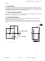
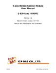
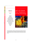
Model DRD-AS Conventional Infrared Flame Detector User Manual Ver. 1.0 Page 1 of 11 DRD-AS Flame Detector User Manual Table of Contents 2 3 4 5 1.1 Description .......................................................................................................................................... 3 1.2 Alarm Response Modes ..................................................................................................................... 3 1.3 IR Detection Basics ............................................................................................................................ 3 Application ................................................................................................................................................ 5 2.1 Detectable Fire Sources ..................................................................................................................... 5 2.2 Typical Applications ............................................................................................................................ 5 2.3 Applications and Locations to Avoid: .................................................................................................. 5 Quantities and Positioning ...................................................................................................................... 6 3.1 Field of View ....................................................................................................................................... 7 3.2 Detector Window Contamination ........................................................................................................ 8 3.2.1 Cleaning ...................................................................................................................................... 8 Installation ................................................................................................................................................. 9 4.1 Functional Testing ............................................................................................................................ 10 4.2 Service & Repairs ............................................................................................................................. 10 Detector Specifications.......................................................................................................................... 11 5.1 Compatible Bases ............................................................................................................................ 11 5.2 Angle Mount Bracket ........................................................................................................................ 11 5.3 Tester................................................................................................................................................ 11 Issued JUN,2011 Page 2 of 11 2011 Hochiki Corporation DRD-AS Flame Detector – Installation Manual General 1.1 Description The flame detector is designed for use where open flaming fires may be expected. It responds to the light emitted from flames during combustion. The detector discriminates between flames and other light sources by responding only to particular optical wavelengths and flame flicker frequencies. This enables the detector to avoided false alarms due to such factors as flicking light sources. 1.2 Alarm Response Modes The detector is normally configured to latch into an alarm state when a flame is detected. The power supply to the detector has to be removed in order to reset the detector. 1.3 IR Detection Basics Flame detectors are classified into two types by their principle of detection. UV detectors are sensitive to ultraviolet, and IR detectors are sensitive to infrared. This DRD-AS detector can detect IR radiated from flames. Flames radiated from a fire have an IR peak emission of 4.3um occurring during the CO2 formation due to the combustion of hydrocarbons from 2 to 15 Hz. Fig 1 : External View of DRD-AS Issued JUN,2011 Page 3 of 11 2011 Hochiki Corporation DRD-AS Flame Detector - Installation Manual Fig 2 : Spectrum of white gas flame The pyroelectric device fitted within the DRD-AS detector, can detect CO2 formation during combustion through an optical filter. The output is amplified from 2 to 15 Hz. The DRD-AS detector will then make a fire decision using an AC-DC converter, comparator, and capacitor. It will then send an alarm signal to the fire panel via a switching circuit. Issued JUN,2011 Page 4 of 11 2011 Hochiki Corporation DRD-AS Flame Detector – Installation Manual 2 Application Flame detectors are used when detection is required to be: Unaffected by convection currents, draughts or wind Tolerant of fumes, vapours, dust and mist Fast reacting 2.1 Detectable Fire Sources Liquids - Aviation Fuels (kerosene), Ethanol, Methylated Spirits, n-Heptane, Paraffin, Petrol (gasoline) Solids – Coal, Cotton, Grain & Feeds, Paper, Refuse Wood Gases – Butane, Natural Gas, Off Gas, Propane 2.2 Typical Applications Coal handling plant Aircraft hangars Atrium Automotive industry - spray booths, parts manufacture Paper manufacture Pharmaceutical Engine rooms Generator rooms Metal fabrication Waste handling Woodworking Power plants Textiles Transformer stations Petrochemical 2.3 Applications and Locations to Avoid: Ambient temperatures above 50°C Location which tends to gather dust or oil film Atmospheres containing corrosive gases Where condensation exists In the vicinity of large IR sources – such as heaters, burners, flares Close proximity to RF sources Obstructions to field of view Exposure to weather Large amounts of flickering reflections Direct sunlight or its reflected light by puddle, glass, or mirror surface of metal Spot lighting directly on the detector optics Issued JUN,2011 Page 5 of 11 2011 Hochiki Corporation DRD-AS Flame Detector - Installation Manual 3 Quantities and Positioning The number of detectors required and their position depends on: the anticipated size of the flame the distance of the flame from the detector the angle of view of the flame detector The DRD-AS flame detector is designed to have a class 1 performance as defined in EN54-10 on the high sensitivity setting. That is the ability to detect an n-heptane (yellow) fire of 0.1m² or methylated spirit (clear) fire of 0.25m² at a distance of up to 25m within 30 seconds. In fact, the DRD-AS flame detector will detect fires at distances of up to 40 metres, but the flame size at such distances needs to be proportionally greater in order to be sure of reliable detection. Thus the yellow flickering flame that can be detected at 25m, provided that its size is not less than 0.1m², will have to be 0.4m² in order to be detected at 40metres. In a rectangular room the distance from the flame detector to the fire is calculated by the formula: Fig 3 : Calculation of distance from detector to flame Issued JUN,2011 Page 6 of 11 2011 Hochiki Corporation DRD-AS Flame Detector – Installation Manual 3.1 Field of View The DRD-AS flame detector has a field of view of approximately 90°, as shown in the diagram below. Fig 4 : Conical field of view of the flame detector Fig 5 : Detector Field of View Plot The DRD-AS flame detector should be positioned at the perimeter of the room, pointing directly at the anticipated flame or at the centre of the area to be protected. If the detector cannot ‘see’ the whole of the area to be protected, one or more additional detectors may be required. The DRD-AS flame detector is not affected by normal light sources but should be positioned so that sunlight does not fall directly onto the viewing window. Issued JUN,2011 Page 7 of 11 2011 Hochiki Corporation DRD-AS Flame Detector - Installation Manual 3.2 Detector Window Contamination It is important to keep the detector window clean and checks should be carried out at regular intervals – determine locally according to the type and degree of contamination encountered – to ensure optimal performance of the DRD-AS flame detector. Although IR detectors can detect flames when the window is contaminated, there may be a reduction of sensitivity. 3.2.1 Cleaning If the window of the DRD-AS flame detector is coated with dust or oil, the sensitivity to flames may decrease. To remove the contamination, use a damp cloth; please ensure to remove any excess moisture with a dry cloth. NOTE: Do not wipe the main body of the detector window with alcohol or benzine. Issued JUN,2011 Page 8 of 11 2011 Hochiki Corporation DRD-AS Flame Detector – Installation Manual 4 Installation The DRD-AS flame detector can be used in conjunction with the following mounting bases: YBN-R/6, YBO-R/6PA. A wall and ceiling mounting bracket are available if required, these should be ordered separately. Please refer to Fig 7 and Fig 8 below. Fig 6 : Installation with Mounting Base Fig 7 : Installation with ceiling bracket (YZU-A) Fig 8 : Installation with wall bracket (YZU-B with YZU-A) Fig 9 : Connection to Conventional Control Panel Issued JUN,2011 Page 9 of 11 2011 Hochiki Corporation DRD-AS Flame Detector - Installation Manual 4.1 Functional Testing A portable flame detector test unit is available to generate simulated flame behaviour (Fig 10.). To test the detector, the test unit needs to be within 600mm of the DRD-AS flame detector. The DRD-AS incorporates a 15 second delay to help filter out any transient IR sources that may occur. Between each test the DRD-AS flame detector will need to be left for minute to allow for stabilisation. If it is safe to do so, a naked flame could also be used to test the DRD-AS flame detector, please ensure that the flame is not exposed directly to the outer casing or lens as damage may occur. < 600mm Fig 10 : Portable Flame Detector Test Unit (Model Name:016061) 4.2 Service & Repairs Servicing of the fire protection system should be carried out by competent persons familiar with this type of system, or as recommended by the local regulations in force. Only the manufacturer or equivalent authorised body may carry out repairs to the flame detectors. In practical terms this means that flame detector may be repaired only at the manufacturer’s factory. Issued JUN,2011 Corporation Page 10 of 11 2011 Hochiki DRD-AS Flame Detector – Installation Manual 5 Detector Specifications Ordering code Operating voltage Standby current Delay time Detection angle Infrared sensitivity range Maximum current in alarm state Remote indicator drive(max) Operating temperature range Maximum humidity Colour and case material Weight DRD-AS 15-30 Vdc (Nominal rating 24Vdc) 70 uA at 24Vdc 15 to 21 Second 90°Cone 2 Class 1 – 0.1m n-heptane at 25m 40mA 20mA -10°C to +50°C 95%RH - Non condensing (at 40°C) White Ivory ABS 125g 5.1 Compatible Bases Order Code Description YBN-R/6 YBO-R/6PA Common Mounting Base. For use with compatible 2-Wire systems. NOTE: Alarm control panel compatibility is required for certain base types. 5.2 Angle Mount Bracket Order Code Description YZU-A YZU-B Ceiling Bracket Wall Bracket (To be used with Ceiling Bracket) 5.3 Tester Order Code Description 016091 Portable Flame Detector Test Unit Issued JUN,2011 Page 11 of 11 2011 Hochiki Corporation