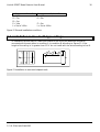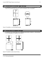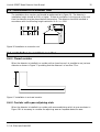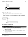
1
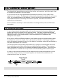
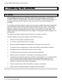
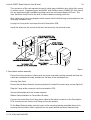
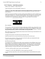
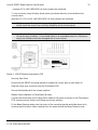
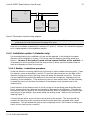
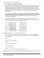
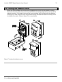
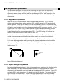
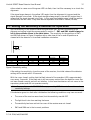
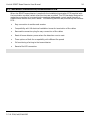
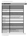
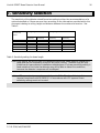
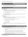
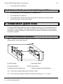
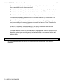
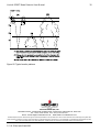
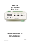
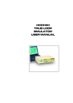
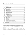
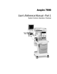
PHOTO-ELECTRIC BEAM DETECTOR
MODEL SPB-ET
INSTALLATION PROCEDURE
Hochiki SPB-ET Beam Detector User Manual
2-3-0-294/Iss2/Feb2001
2
Hochiki SPB-ET Beam Detector User Manual
3
Contents
Contents
3
1.1. General Description
5
1.2. Detection principle
5
2. Installing the detector
6
2.1.
2.2.
2.3.
2.4.
2.5.
2.6.
2.7.
2.8.
Siting
Mounting and removing the detector
Opening the detector cover
Installation
Closing the detector cover
Adjustment procedure
Setting the Sensitivity & Switches for Operation
Sensitivity check procedure
3. Maintenance
3.1.
3.2.
3.3.
3.4.
3.5.
General
Visual check
Operation checks
Precautions for insulation resistance checking
Re-initialisation after cleaning or re-adjustment
4. Terminal layout and part designation
4.1. Emitter
4.2. Receiver
5. Summary of the SPB-ET's functions
5.1.
5.2.
5.3.
5.4.
5.5.
5.6.
5.7.
Alarm signal output and indicator lamp
Fault signal output and indicator lamp
Indication of normal operation
Sensitivity setting
Total obscuration of the beam
Automatic compensation for change of signal strength
Receiver installation/termination PCB
6
7
8
8
15
16
17
18
19
19
19
19
19
19
20
20
21
22
22
22
23
23
23
23
24
6. Specification
25
7. Sensitivity selection
26
8. Troubleshooting
27
8.1. Monitor LED fails to flash
8.2. Fire signal continues after reset
2-3-0-294/Iss2/Feb2001
27
27
Hochiki SPB-ET Beam Detector User Manual
8.3.
8.4.
8.5.
8.6.
8.7.
8.8.
Fault signal cannot be reset
Detector in 'fire' - panel not registering condition
Detector in 'fault' - panel not registering condition
Fault signal cannot be reset
Detector in 'fire' - panel not registering condition
Detector in 'fault' - panel not registering condition
9. Installation guide lines
9.1.
9.2.
9.3.
9.4.
9.5.
9.6.
9.7.
9.8.
General installation conditions
Installation in Saw-tooth type ceilings
Installation in circular type ceilings
Installation in sloped ceilings
Installation in a monitor roof
Installation in corridors or aisles
Installation precautions
Smoke Patterns
2-3-0-294/Iss2/Feb2001
4
28
28
28
28
28
29
29
29
30
31
31
32
32
33
34
1.1. General Description
The photoelectric beam detector consists of an emitter and a receiver, which face each other
at a distance of between 5 and 100 meters.
In the event of fire the smoke generated will decrease the amount of near infrared light
incident on the receiver. This decrease is electronically interpreted to identify the occurrence
of fire. An important feature of the detector is that it monitors the protected space linearly.
This enables the detector to identify a fire before it spreads, even when the smoke is
scattered over a large area.
The fire detection sensitivity is switch selectable in 3 settings of 25%, 50% and 70% beam
obscuration.
1.2. Detection principle
A near infrared pulsed beam generated by the emitter is sensed by the photo-diode of the
receiver, where it is converted into an electrical signal. This signal is then amplified and
applied via an A/D converter to a microprocessor. The normal state signal (the initial beam
data) once stored in the microprocessor is used as a reference for comparison with
subsequent beam signals.
When there is sufficient difference between actual beam strength and stored reference data
to indicate the occurrence of a fire, then a fire signal is produced. A fault signal together
with a fire signal is generated if the axis of the beam is completely obstructed (as opposed to
the partial obscuration due to smoke).
The microprocessor also provides compensation for a change in received signal value with
time, caused by contamination of the optics or slight alignment changes. The processed
signal is adjusted at a rate of ±0.5% towards the reference data every hour. When the limit
of compensation is reached the microprocessor will automatically produce a fault signal.
In order to improve the performance of the detector and to enhance the rejection of noise
the emitter and receiver are synchronised together and therefore the emitter must be
powered directly from the receiver.
2-3-0-294/Iss2/Feb2001
Hochiki SPB-ET Beam Detector User Manual
6
2. Installing the detector
2.1. Siting
Select a suitable position for the installation of both emitter and receiver, such that there are
no visible obstructions between them. Remember that the beam detector works on the
principle of reduction of light between the receiver and emitter. If there is any possibility of
an object remaining within the beam for a few seconds then the siting of the detector is
unsuitable.
For mounting either the emitter or receiver it is important to establish that the mounting place
such as the wall is solid and that the beam detector alignment will be rigid. The wall may
appear to be solid, but may be subject to twisting or other changes when the temperature
outside the building varies greatly during one day, for instance on cold, frosty days. The
installer must ensure that the beam will not be subject to misalignment due to changes in the
building itself.
The spacing and siting in specific types of locations is covered in section 9.
The beam detector must not be installed in the following locations: 4
Where the ceiling height is greater than 40m
4
A roof top or place where open air circulates
4
Where the distance between top and bottom of the space is less than 0.5m
4
In locations where a large amount of dust, fine powder or water vapour is present
4
In locations such as kitchens where smoke occurs normally
4
In locations which are exposed to extremely high temperatures
4
Where access to the detector is impossible for maintenance purposes
4
In locations which may be exposed to sunlight exceeding 5000 lux. it is recommended
that in locations where the beam detector may be surrounded by glass, then the
receiver should where possible be fitted so that it faces a northerly direction (only
relevant to countries in the northern hemisphere)
4
Where the rigid fixing of either the emitter or receiver is impossible
4
Where access to the beam detector to align and set is impossible
2-3-0-294/Iss2/Feb2001
Hochiki SPB-ET Beam Detector User Manual
2.2. Mounting and removing the detector
The detector can be fixed to the metal bracket by hooking the detector body to the four
prongs of the mounting plate and then by sliding down firmly until the detector is locked
into place and then locking using the locking screw (see Fig 1).
Removal of the detector can be achieved by slackening the locking screw and pressing the
locking mechanism located on the bottom left hand side of the detector housing. Whilst
pushing the locking mechanism with either a narrow rod or screwdriver the detector is lifted
upwards until it disengages from the mounting plate.
Figure 1 Locking mechanism
2-3-0-294/Iss2/Feb2001
7
Hochiki SPB-ET Beam Detector User Manual
8
2.3. Opening the detector cover
Hold the detector cover between the thumb and fingers near the top of the cover and
squeeze the cover firmly so that the top of the cover expands slightly. The cover can then be
pulled away from the detector housing. This should be done by pulling the cover at an angle
of 45° upwards and away from the detector.
Next hold the detector cover firmly at the bottom and pull away from the detector housing
until a click is heard. The cover should now be able to drop down and rest on the cover
retaining clips, thus allowing access inside the detector housing. Refer to Figure 2 for more
details.
Figure 2 opening the detector housing
2.4. Installation
The detector is available in two installation options, depending on the country and wiring
requirements. Please check that the beam detector contains the correct components for the
option required.
Option 1 SPB-ET (including termination module SPB-ET2WI), refer to section 2.4.1 for
installation details:
1 Emitter
1 Receiver
1 Installation manual
4 Fixing screws
2-3-0-294/Iss2/Feb2001
Hochiki SPB-ET Beam Detector User Manual
9
1 Emitter mounting plate (termination module PCB on the back)
1 Receiver mounting plate (termination module PCB on the back)
1 2-way cable for connection between mounting plate and emitter
1 10-way cable for connection between mounting plate and receiver
3 Installation test filters
Option 2 SPB-ET (detector only); refer to section 2.4.2 for installation details:
1 Emitter
1 Receiver
2 Metal mounting brackets
1 Installation manual
4 Fixing screws
3 Installation test filters
The installation method varies depending upon the installation option used. For correct
installation refer to the relevant instructions for the installation option.
2.4.1. Installation option 1 (with termination module)
The termination module is designed to facilitate installation of the SPB-ET beam detector to
fire cables using a standard surface/flush dual gang installation box. The module also
provides three types of fault monitoring configurations, simple beam reset and remote fire
indication.
2.4.1.1. Emitter - Installation Procedure
Ribbon cable installation to Beam Detector:
Open the detector cover as described in section
Thread the 2 way ribbon cable through the back of the beam detector, so that the connector
remains at the rear of the beam detector and the flying leads exit the bottom front of the
beam detector.
Install the harness into the beam connector starting with the Red wire to E2 and the Brown
wire to E1. The wires should be pushed into the holes of the connector whilst the white push
key is pressed with a small screwdriver. This will enable the wire to push completely home.
Pull the wire to make sure that it is firmly held by the connector.
Wire Installation:
2-3-0-294/Iss2/Feb2001
Hochiki SPB-ET Beam Detector User Manual
10
The connection of this unit requires the use of a dual gang installation box, either flush mount
or surface mount. Suggested types are MK897 ALM surface mount, MK862 ZIC flush mount,
but any equivalent type is suitable providing that it has a minimum depth of 25mm. This
item should be firmly fixed to the wall or other suitable mounting point first.
With reference to the wiring diagram below ensure that the field wiring is terminated into the
dual gang installation box.
Unplug the 2 way white connector from the Termination PCB.
Install the wires into the correct socket slot and secure by the terminal screw.
Figure
3 Termination module assembly
Ensure the white connector is facing with the screw terminals pointing upwards and that the
cables are insulated and neatly located into the base of the installation box.
Securing Face Plate:
Ensure that the Beam Detector mounting bracket is located the correct way up (see Figure 3).
Plug the 2 way white connector into the termination PCB.
Secure the faceplate with the screws supplied.
Ribbon Cable Installation to Termination Module:
Connect the socket from the 2-way ribbon cable to the white connector on the Termination
PCB, ensuring correct friction lock fitting and correct polarity.
Fit the Beam Detector body onto the hooks of the mounting bracket and slide down to fix,
ensuring that the ribbon cable is pushed into the space behind the Beam Detector body.
2-3-0-294/Iss2/Feb2001
Hochiki SPB-ET Beam Detector User Manual
11
2.4.1.2. Receiver - Installation procedure
Ribbon cable installation to Beam Detector:
Open the detector cover as described in section 2.3.
Thread the 10 way ribbon cable through the back of the beam detector, so that the connector
remains at the rear of the beam detector and the flying leads exit the bottom front of the
beam detector.
Install the harness into the beam connector starting with the Black wire to E1 and following in
cable order through to FC. The wires should be pushed into the holes of the connector whilst
the white push key is pressed with a small screwdriver. This will enable the wire to push
completely home. Pull the wire to make sure that it is firmly held by the connector.
Beam Detector (Receiver) Connections
DC
TO L2
DO FC F O T
C
W
H
T
G
R
Y
V
L
T
B
L
U
C2
G
R
N
C1
Y
L
W
L1
O
R
G
E2
R
E
D
E1
B
R
N
B
L
K
Termination Module Connector
Wire Installation:
The connection of this unit requires the use of a dual gang installation box, either flush mount
or surface mount. Suggested types are MK897 ALM surface mount, MK862 ZIC flush mount,
but any equivalent type is usable providing that it has a minimum depth of 25mm. This item
should be firmly fixed to the wall or other suitable mounting point first.
With reference to the wiring diagram above ensure that the field wiring is terminated into the
dual gang installation box.
Unplug the 8 way white connector from the Termination PCB.
Install the wires into the correct socket slot and secure by the terminal screw.
Ensure the grey connector is facing upwards and that the cables are insulated and neatly
located into the base of the installation box.
Fault Monitoring Selection:
The module can be configured to provide correct operation for three different types of zone
fault indication, which provide the same fault detection functions as Hochiki's conventional
detector bases when the detector heads are removed. The configuration is achieved using
jumpers at the top of the termination PCB (refer to figure 4) and the selection should be
made according to the type of fire alarm control panel being used.
1. No line continuity option (zone is open circuit during fault)
Jumpers LK1, LK4 & LK6 ARE MADE; all other jumpers are removed
2. Line continuity using Zener circuit option (produces detector removal fault at the control
panel)
2-3-0-294/Iss2/Feb2001
Hochiki SPB-ET Beam Detector User Manual
12
Jumpers LK2 & LK5 ARE MADE; all other jumpers are removed
3. Line continuity using Schottky diode option (produces detector removal fault at the
control panel)
Jumpers LK1, LK3, LK4 & LK6 ARE MADE; all other jumpers are removed.
Note: The Termination Module is factory configured for Schottky diode line continuity. If in
doubt check the correct line continuity suitability for the control panel.
Warning: When the Zener option is used it must be connected to a control panel that is able
to use this type of option. If connected either to an unsuitable panel or a 24V power
supply the interface could be damaged due to over-current.
Figure 4 - SPB-ET Receiver termination PCB
Securing Face Plate:
Ensure that the SPB-ET mounting bracket is located the correct way up (see Figure 3).
Plug the 8 way grey connector into the Termination PCB.
Secure the faceplate with the screws supplied.
Ribbon Cable Installation to Termination Module:
Connect the socket from the 10-way ribbon cable to the white connector on the Termination
PCB, ensuring correct friction lock fitting and correct polarity.
Fit the Beam Detector body onto the hooks of the mounting bracket and slide down to fix,
ensuring that the ribbon cable is pushed into the space behind the Beam Detector body.
2-3-0-294/Iss2/Feb2001
Hochiki SPB-ET Beam Detector User Manual
13
Zone +
+
Zone -
-
Fire Alarm
Control Panel
Z+ Z+ Z- ZPan EOL Pan EOL
E1
E1
E2
E2
Beam Detector
(Receiver)
Beam Detector
(Emitter)
Figure 5 Termination module wiring diagram
Note: Beam detectors should be installed to comply with local installation requirements
governing the maximum area of coverage for a zone.
Now set up the beam as described in sections 2.7 and 2.6. Section 2.4.2 should be skipped,
as it is inappropriate to this installation version.
2.4.2. Installation option 2 (detector only)
For some applications the installation kit may not be required, in this situation the beam
detector can be installed on its own, if this is the case the detector should be wired as in
figure 6. However if this method is used no head removal facilities will be available. It
is necessary to wire the emitter from the receiver with 2-wires, since the emitter does not
work as a separate unit from the receiver.
2.4.2.1. Emitter - Installation procedure
Screw the detector mounting plate firmly to the wall or other suitable mounting point. Open
the detector cover as described in section 2.3 and then take the wires into the back of the
detector through the hole so that they come out below the terminal connector. The wires
can be installed either behind the detector or from below the detector, depending on the
suitability of the installation. If the wires are to come in from below then it will be necessary
to break the knock-out slot from the bottom of the detector body (located near to the
retaining clip).
Hook the back of the detector body to the 4 prongs of the mounting plate and slide down
firmly, ensuring that the cables are not trapped or damaged by the detector. The detector
body should lock into place by the locking mechanism, which is located on the bottom right
hand corner of the detector, and secure using the locking screw. Refer to the mechanical
drawing Figure 1.
Connect the two wires, which run from the receiver to the emitter. The wires should be
pushed into the holes of the connector whilst the white push key is pressed with a small
screwdriver. This will enable the wire to push completely home. Pull the wire to make sure
that it is firmly held by the connector.
2-3-0-294/Iss2/Feb2001
Hochiki SPB-ET Beam Detector User Manual
14
2.4.2.2. Receiver - Installation procedure
Screw the detector mounting plate firmly to the wall or other suitable mounting point. Open
the detector cover as described in section 2.3 and then take the wires into the back of the
detector through the hole so that they come out below the terminal connector. The wires
can be installed either behind the detector or from below the detector, depending on the
suitability of the installation. If the wires are to come in from below then it will be necessary
to break the knock-out slot from the bottom of the detector body (located near to the
retaining clip).
Hook the back of the detector body to the 4 prongs of the mounting plate and slide down
firmly, ensuring that the cables are not trapped or damaged by the detector. The detector
body should lock into place by the locking mechanism, which is located on the bottom right
hand corner of the detector and then secured using the locking screw. Refer to the
mechanical drawing Figure 1.
The wires should be pushed into the holes of the connector whilst the white push key is
pressed with a small screwdriver. This will enable the wire to push completely home. Pull
the wire to make sure that it is firmly held by the connector.
ZONE PAN
L1 (L+ IN)
+ Ve
C1 (L- IN)
- Ve
NOT USED
L2 (L+ OUT)
- Ve
C2 (L- OUT)
+ Ve
TC (COM)
ZONE EOL/
NEXT DETECTOR
EMITTER
RECEIVER
FO (FIRE LED + Ve)
E1
E1
FC (FIRE LED -Ve)
E2
E2
Figure 6 Wiring diagram for use without the installation kit
The connections for the emitter and receiver are detailed below. The terminal names are
marked above the terminals on the beam detector. Refer to section 4 for a drawing of the
terminal positions.
Emitter:
E1, E2 to E1, E2 of the receiver
Receiver:
E1, E2 to E1, E2 of the emitter
L1 +Ve in, C1 -Ve in
C2 -Ve out, TC +Ve out
Now set up the beam as described in the following sections.
2-3-0-294/Iss2/Feb2001
Hochiki SPB-ET Beam Detector User Manual
15
2.5. Closing the detector cover
Move the cover upwards so that the cover engages with the top of the detector housing.
Then hook the top of the cover over the metal hook protruding outward from the top of the
detector housing. Pull down the top of the cover ensuring that it is flush with the detectorhousing top. Now push the cover at the bottom firmly towards the detector housing until it
locks back into place. Refer to Figure 7 for more details.
Figure 7 closing the detector cover
2-3-0-294/Iss2/Feb2001
Hochiki SPB-ET Beam Detector User Manual
16
2.6. Adjustment procedure
The adjustment procedure is carried out by first using the sight holes and alignment
adjustment screws. Following this the signal strength is adjusted by using the signal
adjustment wheels (coarse and fine) and the signal strength LED's. Refer to section 4 for
details of the position of the relevant parts on the detector when making the following
adjustments.
2.6.1. Alignment adjustment
Open the covers of the emitter and receiver as described previously. At the receiver,
confirm that both sensitivity setting switches SW1 and SW2 are set to OFF (sensitivity off),
refer to Figure 9. Power up the receiver (this will automatically power up the emitter) and
then wait two minutes for the beam detector to stabilise. At this time the red operating LED
will flash in synchronisation with the red alignment setting LED once every second. On the
receiver one of the 6 small LED's located between the terminals and the normal monitor
LED's will be flashing (these LED's are small square LED's located in the main PCB and are
located below the main alignment and status LED's). The LED flashing will indicate the
amount of light reaching the receiver (refer to figure 10).
Move to the emitter and look through the alignment sight hole. Turn either the horizontal or
vertical alignment screws until the receiver can be seen in the centre of the sight hole.
When installing the units in a dimly lit area, it may be difficult to see the receiver and emitter.
In this case alignment can be made by turning the alignment adjustment wheels until the
alignment setting LED can be seen in the centre of the sight hole.
Close the cover of the emitter, move to the receiver and repeat the alignment procedure
(refer to figure 11).
Sight Hole
Other Detector
Figure 8 Detector alignment
2.6.2. Signal strength adjustment
First, set both adjustment wheels to their minimum setting by rotating so that the front of the
wheel as turned all the way to the bottom and then turn the adjustment wheel (coarse
adjustment) until the further most right hand red signal strength LED is flashing. These LED's
are small square LED's located in the main PCB and are located below the main alignment
and status LED's - refer to section 4 if in doubt as to the LED location. This means that the
signal strength is at a maximum. Adjust either the fine adjustment wheel or the coarse
adjustment wheel until one of the green signal LED's flashes. If it is not possible to adjust
2-3-0-294/Iss2/Feb2001
Hochiki SPB-ET Beam Detector User Manual
17
either wheel to cause one of the green LED's to flash, then it will be necessary to re-check the
alignment.
If the signal stays always in the yellow LED region then the alignment is incorrect and the
signal strength is too weak. If the signal strength always stays in the red LED region then it
means that the signal strength is too high. In this case the probable cause is that the emitter
and receiver are too close. They must have a separation of at least 5 meters (16 feet).
2.7. Setting the Sensitivity & Switches for Operation
Set the sensitivity to the required value using switches SW1 and SW2 according to the
distance and ceiling height as recommended in section 7. SW3 and SW4 should always be
left in the positions shown in the table below. The sensitivity for the positions of SW1
and SW2 are shown in Figure 9 together with a side view of the on and off positions as
viewed with the detector in its normal installation orientation.
ON
OFF
SW1 position
OFF
ON
OFF
ON
SW2 position
OFF
OFF
ON
ON
SW3 position
OFF
OFF
OFF
OFF
SW4 position
ON
ON
ON
ON
Percentage
Obscuration
25%
50%†
70%†
dB's
Obscuration
1.25
3.01†
5.23†
Figure 9 Sensitivity setting
After setting the sensitivity, close the cover of the receiver; the initial values of the detector
setting will be stored within 10 seconds.
With the cover closed, confirm that the flash interval of the operation LED is approximately
once every 3 seconds. If the flash rate is still once every second then the detector cover has
not been closed correctly and will not initialise. In this case the detector will not move to the
supervisory status and will not operate correctly.
† Note: For compliance with BS 5839 Pt 5 as approved by LPCB it is not allowed to use these
sensitivity settings.
If the detector goes into fault after initialisation the following conditions may have occurred: 4
The cover of the receiver was closed, but the sensitivity was left OFF
4
The light level is too low reaching the beam
4
The sensitivity has been set but the cover of the receiver was not closed
4
SW3 and SW4 are in the incorrect positions
2-3-0-294/Iss2/Feb2001
Hochiki SPB-ET Beam Detector User Manual
18
Run through the alignment and signal strength procedure again until the beam detector will
initialise correctly.
2.8. Sensitivity check procedure
After installing the detector or during periodic maintenance it is important to ascertain that
the detector has the correct fire sensitivity. This can be achieved by the use of filters. Hochiki
produce two types of filters for this purpose, the first being the TSK-B100, the second being
the TBF-E.
2.8.1. Using the TSK-B100
These filters have been designed as rugged long lasting test filters for testing all models of
Hochiki beam detector and have been manufactured from wire mesh. They also come with
an attachment so that they can be mounted to the Hochiki detector removal pole, thus
enabling testing of the filter from ground level.
First determine the sensitivity that the beam detector should be set to and then select the
correct filter values from Table 1. Using the lowest filter value prove that the detector is not
too sensitive by placing the filter between the emitter and receiver for at least one minute. It
is not set to the correct sensitivity if the detector goes into fire alarm (or fault) during this
process.
Next place the higher value filter between the emitter and receiver for at least one minute.
During this period a fire alarm should occur. If no alarm occurs or a fault occurs then the
detector is not operating as expected.
Sensitivity setting
(%)
25
50
70
Type of test
Filter Value
Filter Number
Operation
Non-operation
Operation
Non-operation
Operation
Non-operation
40%
15%
65%
30%
85%
40%
No.4
No.2
No.5
No.3
No.6
No.4
Table 1 TSK-B100 test filter values
2.8.2. Using the TBF-E
These filters have been designed as disposable test filters for testing the Hochiki SPB-ET beam
detector and have been manufactured from plastic. They are either supplied as a separate
item or are included in the option with termination module. They are intended to be used
once and then thrown away as due to their construction the characteristics cannot be
guaranteed over a long period.
First determine the sensitivity that the beam detector has been set to and then select the
correct filter from the set according to the text on the filters. Range 1 relates to 25%, range 2
to 50% and range 3 to 70% sensitivity setting. Using the No Alarm filter, prove that the
detector is not too sensitive by placing the filter between the emitter and receiver for at least
one minute. It is not set to the correct sensitivity if the detector goes into fire alarm (or fault)
during this process.
2-3-0-294/Iss2/Feb2001
Hochiki SPB-ET Beam Detector User Manual
19
Next place the Alarm filter between the emitter and receiver for at least one minute. During
this period a fire alarm should occur. If no alarm occurs then the detector is not operating as
expected.
Note: When testing the 70% sensitivity setting it is possible that the alarm filter may produce
a fault signal as well as a fire alarm signal.
3. Maintenance
3.1. General
The detector contains an automatic compensation function, which allows the detector to
operate correctly even when the amount of signal reaching the receiver has changed (the
compensation rate is ±0.5%/hour). This means that minor changes due to contamination and
beam alignment will not affect the sensitivity of the detector. There is of course a limit that
the detector can compensate for and this is -50% and +20% of the initial setting. In order to
maintain proper performance the detector should be checked every six months.
3.2. Visual check
Check the condition of both the emitter and receiver for physical damage or any other
condition that might impair proper operation. Ensure that both the receiver and emitter are
still firmly secured to the wall or other fixing point.
If necessary clean the lens cover with a damp soft cloth. Washing liquid or detergent must
not be used.
3.3. Operation checks
Perform the sensitivity check function as defined in section 2.8.
3.4. Precautions for insulation resistance checking
If the wiring to a beam detector is to be tested for insulation resistance using a high voltage
tester such as a Megger, the wiring to the beam detector must be disconnected from the
detector otherwise permanent damage of the detector may result. If the termination module
is used then the disconnection of the orange terminal connector from the PCB will enable
testing to be carried out.
3.5. Re-initialisation after cleaning or re-adjustment
Because the beam detector contains sophisticated processing algorithms to take account of
fluctuations in the beam intensity and alignment, if during routine maintenance the beam
2-3-0-294/Iss2/Feb2001
Hochiki SPB-ET Beam Detector User Manual
20
detector lenses have been cleaned or re-aligned then it will be necessary to make the
detector read and store its initial value. This can be done by one of two methods: - Either by removing the power from the detector for more than the data hold time (stated in
the specification section 6).
- Or by switching the sensitivity off (DIP switch bits 1 and 2 to OFF) and then back to the
required sensitivity.
4. Terminal layout and part designation
4.1. Emitter
Figure 10
Light Beam Adjustment
Screw (Vertical)
Light Beam Adjustment
Screw (Horizontal)
Operating Indicator
LED (red)
E1 E2
Emitter Wiring Terminals
2-3-0-294/Iss2/Feb2001
Alignment Setting Led (red)
Hochiki SPB-ET Beam Detector User Manual
21
4.2. Receiver
Signal Adjustment
Screw (Fine)
Signal Adjustment
Screw (Coarse)
Light Beam
Adjustment Screw
(Vertical)
Light Beam
Adjustment
Screw (
Horizontal)
Fault LED (Yellow)
Alignment Setting
LED (Red)
Sensitivity
Adjustment LED
(Green)
Operating Indicator and
Fire LED (Red)
Sensitivity Adjustment
LED (Yellow)
DC DO FC FO TC TO L2 C2 C1 L1 E2 E1
Switches SW3, SW4
Switches SW3, SW4 must
always be in these positions
Figure 11
2-3-0-294/Iss2/Feb2001
Sensitivity
Adjustment
LED (Red)
Sensitivity Switches
SW1, SW2
Switches SW1, SW2
positions can be varied
according to which
sensitivity has been
selected
Hochiki SPB-ET Beam Detector User Manual
22
5. Summary of the SPB-ET's functions
5.1. Alarm signal output and indicator lamp
When the beam is obscured by an amount that exceeds the sensitivity setting of the detector
then a fire signal is produced by closing the fire relay contact and lighting the fire LED on the
receiver.
It should be noted that the SPB-ET has a sophisticated processing and analysing circuit and
therefore a fire will not occur immediately the obscuration exceeds the sensitivity value, but
will take typically 10 to 15 seconds to produce the fire signal. The fire decision is based on
an averaging technique and therefore the time to fire alarm will vary depending on the level
of obscuration and the sensitivity setting.
5.2. Fault signal output and indicator lamp
5.2.1. General
The beam detector may produce a fault condition for one of many different reasons, which
will depend on whether the detector has just been set up or is in normal operation. The fault
signal will be produced by opening the fault relay contact and illuminating the yellow fault
LED on the receiver.
5.2.2. After adjustment/re-initialisation
The beam detector will produce a fault after or during adjustment for one of the following
reasons:
4
The cover of the receiver was closed, but the sensitivity was left OFF
4
The light level is too low reaching the beam
4
The light level is too high reaching the beam
4
The sensitivity has been set but the cover of the receiver was not closed within 5
minutes
4
SW3 and SW4 are in the incorrect positions
5.2.3. During normal operation
The beam detector will produce a fault during normal operation for one of the following
reasons:
4
The cover on the receiver has been opened for more than 5 minutes.
2-3-0-294/Iss2/Feb2001
Hochiki SPB-ET Beam Detector User Manual
23
4
The limit of contamination has been reached. The detector is only able to compensate
for contamination or alignment change up to a certain point
4
The obscuration is greater than 90% (a fire alarm signal will also be produced)
4
The power has been removed for more than 30 seconds and when powered up the
initial received data is too low.
5.3. Indication of normal operation
When the covers of the receiver or emitter are closed then the red LED visible through the
outside of the case will flash every 3 seconds to indicate that the detector is operating
correctly.
If the cover of the receiver is open then both red LED's (the centre alignment LED is not
visible unless the cover is open) on the receiver will flash every second. The opening of the
receiver cover will make the LED's on the emitter and receiver flash at the faster 1 flash per
second rate.
If the cover of the emitter is open then both red LED's on the receiver will flash. The rate of
flash will not be affected by opening the cover of the emitter.
5.4. Sensitivity setting
The receiver is provided with a DIL switch with 2 bits available for setting the sensitivity of
the beam detector. The settings can be 25%; 50%; 70% or no operation.
The sensitivity setting only affects the determination of the fire signal. Basically the higher the
percentage setting, the less sensitive the beam detector will be since the production of a fire
signal requires that the signal seen by the receiver should be reduced by more than the
amount of the sensitivity setting. For example a sensitivity of 25% requires a reduction of the
signal by 1/4 of its initial value to produce a fire.
5.5. Total obscuration of the beam
If the beam detector is totally obscured, then a fault signal will be produced first followed by
a fire signal within a few seconds. This has been implemented in this way, as the total fault
obscuration may not really be a fire condition. The fault condition will disappear when the
total obscuration condition is removed, but the fire alarm will remain until the beam detector
is reset.
5.6. Automatic compensation for change of signal strength
From the time that the beam detector is initialised, the signal at the receiver is checked every
hour for variation and will be altered by ±0.5% back towards the original stored value. The
beam detector will store the initialisation value, when either the cover is closed after the
sensitivity has been set (sensitivity not in the no operation position) or if the beam detector is
powered up with the sensitivity set and the receiver's cover closed.
2-3-0-294/Iss2/Feb2001
Hochiki SPB-ET Beam Detector User Manual
24
5.7. Receiver installation/termination PCB
When the SPB-ET beam detector is used with the installation/termination PCB (supplied with
the termination module) certain other functions are provided. This PCB has been designed to
make the connection to a conventional or analogue addressable control panel (through a
suitable zone monitor unit) much easier. The following facilities are provided by the interface
PCB: 4
Easy connection to emitter and receiver
4
Compatibility with UK electrical installation boxes for termination of fire cables
4
Removable connection plug for easy connection of fire cables
4
Reset of beam detector power when fire detection zone is reset
4
Three options of fault for compatibility with different fire panels
4
Full monitoring of wiring to the beam detector
4
Remote Fire LED connection
2-3-0-294/Iss2/Feb2001
Hochiki SPB-ET Beam Detector User Manual
6. Specification
Installation Environment
Principle of Operation
Rated voltage
Operating voltage range
Peak surge voltage
Current in alarm
Non-alarm current (SPB-ET
only)
Non-alarm current (Interface
module with SPB-ET)
Indoor use only
Light beam obscuration (near infra-red)
24V
15.0 ~ 33V dc
42V
50mA
250µA
Initial data hold time
Compensation method
Compensation limits
Fire condition
Fault condition
Monitor condition
Typically 30 seconds
0.5% per hour towards initial value
+20% to -50% of the initial value
Red fire LED on receiver lit & 470 ohm across zone
Yellow fire LED on receiver lit & line continuity options
Cover open: Both left hand and central 5mm red LED's
flash
Cover closed: Left hand 5mm red LED flashes
Receiver cover open: 1 per second
Receiver cover closed: 1 per 3 seconds
90%
Monitor condition flash
repetition time
Minimum level determined
as total obscuration (fire and
fault together)
Minimum time needed to
reset from fire
Minimum time needed
before beam can reset after
fire produced
Operating temperature range
Maximum humidity
Beam length
Sensitivity
Size (emitter or receiver)
Weight (without termination
module)
Colour
Housing material
Mounting
Connection method
Wiring method
Number of wires between
emitter and receiver
2-3-0-294/Iss2/Feb2001
From detection
zone:
100msec
3 seconds
-10°C to 50°C
95% R.H.
5m to 100m
25%; 50% or 70% obscuration
86mm x 100mm
Emitter: 425g. Receiver: 490g
White Ivory (Black lens)
ACS resin
Wall mounting
SPB-ET: Push in terminals
Termination module: screw terminals
SPB-ET only: 2 wire
Termination module: 2 wires for zone
2 wires (non polarised)
25
Hochiki SPB-ET Beam Detector User Manual
26
7. Sensitivity selection
The sensitivity of the detector should be set according to either the recommendations of a
national standard or if there are none then according to the information provided within this
document relating to ceiling height and distance between the emitter and receiver. See
Table 2.
Distance between
receiver and
emitter
5 to 10m
10 to 26m
26 to 30m
30 to 81m
81 to 100m
Ceiling height less than 15m
Ceiling height more than 15m
Maximum
sensitivity
Minimum
sensitivity
Maximum
sensitivity
Minimum
sensitivity
25%
50%
50%†
75%†
75%†
25%
25%
25%
25%
50%†
25%
25%
50%†
50%†
50%†
25%
25%
25%
25%
50%†
Table 2: Sensitivity setting for beam length
Note:These figures are derived from the regulations governing beam detector installation in
Japan and are not necessarily correct for any other country. Therefore they are only
guidelines for beam detector installations outside Japan. If a lower sensitivity setting is
used outside of the limits the detector may still be able to detect fire conditions,
however the detector's response will be delayed.
† Note: LPC approval only covers the sensitivity set to 25%. Therefore if the installation
requires compliance with BS 5839 Pt 5 in accordance with LPC approval these
sensitivity settings must not be used.
2-3-0-294/Iss2/Feb2001
Hochiki SPB-ET Beam Detector User Manual
27
8. Troubleshooting
The following conditions relate to the SPB-ET itself.
8.1. Monitor LED fails to flash
8.1.1. Receiver
The monitor LED should flash every 3 seconds (every 1 second if the cover on the receiver is
open). If it does not the reason may be as follows: 4
Zone voltage to the receiver less than 15V
4
Receiver is damaged
Ensure that the receiver has been powered for more than 30 seconds and that the power at
the receiver is greater than 15V.
8.1.2. Emitter
The monitor LED should flash every 3 seconds (every 1 second if the cover on the receiver is
open). If it does not the reason may be as follows: 4
No power on the emitter (wiring short circuit or open circuit)
4
Zone voltage to the receiver less than 15V
4
Receiver is damaged
4
Emitter is damaged
Ensure that the power at the emitter is present (approximately 8V) and also that the receiver
is working.
8.2. Fire signal continues after reset
When a fire has occurred there may be certain circumstances that will prevent the beam
detector from resetting. These are: 4
There is an obstruction of the optical path between emitter and receiver. Ensure there is
no obstruction.
4
The optical axis has been altered suddenly. The beam will need re-alignment.
4
The emitter has stopped working. Check the voltage is present at the emitter.
4
Insufficient time between fire and reset. At least 3 seconds are required before resetting
the beam after the fire signal has occurred.
2-3-0-294/Iss2/Feb2001
Hochiki SPB-ET Beam Detector User Manual
28
8.3. Fault signal cannot be reset
8.3.1. Fire also occurs
If a fire and fault occur at once it is because the beam detector has been totally obscured. The
reason will be the same as for 8.2 above.
8.3.2. Fault only
If a fault has been generated without any obvious reason, it has occurred due to one of the
following reasons: 4
Contamination limit has been exceeded (light received has changed by more than 50%)
4
The CPU in the detector has lost its stored initial values and the CPU is unable to
initialise the detector correctly as the values read are out of range
4
The detector cover has been closed without setting the sensitivity
4
SW3 and SW4 are in the incorrect positions
To clear these conditions the set up and adjustment procedure should be repeated.
8.4. Detector in 'fire' - panel not registering condition
4
The zone is incorrectly wired to the beam detector. The wiring must be done in
accordance with the relevant wiring diagram
8.5. Detector in 'fault' - panel not registering condition
4
The zone is incorrectly wired to the beam detector. The wiring must be done in
accordance with the relevant wiring diagram
The following conditions relate to the SPB-ET if it is used with the termination module (option
1). The conditions already mentioned still apply.
8.6. Fault signal cannot be reset
If the fault cannot be reset it will be due to the following: 4
Beam detector is defective or removed from interface PCB
8.7. Detector in 'fire' - panel not registering condition
4
Panel does not use 470 ohms to detect a fire condition
4
The control panel is incompatible with the interface PCB
2-3-0-294/Iss2/Feb2001
Hochiki SPB-ET Beam Detector User Manual
4
29
The interface PCB is defective
8.8. Detector in 'fault' - panel not registering condition
4
The control panel is incompatible with the interface PCB
4
The interface PCB is defective
4
The interface fault monitoring jumpers have been incorrectly set. Verify the fault
monitoring function of the control panel
9. Installation guide lines
The Hochiki SPB-ET beam detector must be installed according to the requirements laid out
in national or local standards. The following guidelines for installation are provided to give
information in certain installation conditions where no advice or regulations are provided by
the relevant standard.
9.1. General installation conditions
Figure 12 relates to the typical installation condition i.e. in a long straight area and details the
siting positions of the beam detector.
H=ceiling height
l1=side wall distance
P=distance between optical axes
h=mounting height
l2=back wall distance
L=distance between Emitter/Receiver
If H ≤ 15m then use beam detectors at locations 1 and 2
If H > 15m then beam detectors should be mounted at locations 1, 2, 3, 4 and 5
2-3-0-294/Iss2/Feb2001
Hochiki SPB-ET Beam Detector User Manual
For Detectors at 1 and 2
h ≤ 0.8H
l1 ≤ 7m
l2 ≤ 1m
P ≤ 14m
L = 5m to 100m
30
For detectors at 3, 4 and 5
h' = H/2
l1 ≤ 5m
P' ≤ 5m
L = 5m to 100m
Figure 12 General installation conditions
9.2. Installation in Saw-tooth type ceilings
In installations where there is a saw-tooth shape to the ceiling the detectors should be
mounted with the axis either in condition A or condition B according to Figure 13. If the
height of the ceiling 'a' is greater than 0.2'H' do not install with the axis according to line B.
Figure 13 Installation in saw-tooth shaped roofs
2-3-0-294/Iss2/Feb2001
Hochiki SPB-ET Beam Detector User Manual
31
9.3. Installation in circular type ceilings
The installation in a cylindrical or circular roofed building should be in accordance with. In the
case of the cylindrical roof position A or B for the detector's axis is acceptable.
Figure 14 Installation in circular shaped ceilings
9.4. Installation in sloped ceilings
The installation for a sloped type roof or ceiling will be as shown in Figure 15. Either position
A or B is acceptable for installation of the SPB-ET.
Figure 15 Installation under a sloped ceiling
2-3-0-294/Iss2/Feb2001
Hochiki SPB-ET Beam Detector User Manual
32
9.5. Installation in a monitor roof
The installation for a monitor roof should be performed as in Figure 16. The detector's
installation height should be 0.8H or higher. If there is ventilation in the top part of the roof
then the detector must be placed below the opening. The detector should be installed in
accordance with the following height restriction: H-a > h ≥ 0.8H
Figure 16 Installation in a monitor roof
9.6. Installation in corridors or aisles
9.6.1. Closed corridor
When the detector is installed in a corridor with a closed corner it is possible to use just one
detector as shown in Figure 17 providing that the distance L is less than 7.5m.
Figure 17 Installation in a closed corridor
9.6.2. Corridor with open adjoining aisle
When the detector is installed in a corridor with an area adjoining which is open as shown in
Figure 18 it is necessary to consider the adjoining area as a separate detection area.
2-3-0-294/Iss2/Feb2001
Hochiki SPB-ET Beam Detector User Manual
33
Figure 18 Installation in an open corridor
9.6.3. Corridor with corners
When the detector is installed in a corridor with a bend and an aisle as shown in
Figure 19 it will be necessary to use at least 2 beam detectors to cover the corridors. If the
distance P is greater than 15m then another beam detector will need to be installed at point
C.
Figure 19 Installation in a corridor with corners
9.7. Installation precautions
The following precautions are necessary when installing beam detectors: 4
In a room where an air inlet is positioned in the ceiling the beam detector should be
placed near to the air inlet.
4
Select an appropriate installation place where the detector is unaffected by air being
drawn into a ventilated opening.
4
The distance between the receiver and the wall immediately behind the receiver should
be less than 7.5m.
2-3-0-294/Iss2/Feb2001
Hochiki SPB-ET Beam Detector User Manual
34
4
If more than one detector is installed they must be positioned in such a manner that
they cannot affect each other's operation.
4
The detector should be positioned such that a shutter or hanging wall will not affect it.
4
The detector should be positioned such that it will be unaffected by moving objects.
4
The detector should not be installed in a rooftop or place where open air circulates.
4
The detector should be installed where the distance between top and bottom of the
space is greater than 0.5m.
4
The monitoring distance between the emitter and receiver is 5m to 100m and the
maximum distance of coverage between the line of the beam is 7.5m. Therefore the
maximum area of coverage is 1500m2.
4
If there is a probability of people walking in the area of the beam then the beam
detector should be installed at least 2.7m from the floor.
4
The beam detector should not be installed at a height greater than 25m unless the fire
detection system is connected directly to the fire brigade or via a central station and
rapid attendance by the fire brigade is possible. In any case the maximum installation
height is 40m.
9.8. Smoke Patterns
The following smoke patterns should be considered when considering beam detector
installation:
2-3-0-294/Iss2/Feb2001
Hochiki SPB-ET Beam Detector User Manual
35
Figure 20 Typical smoke patterns
HOCHIKI EUROPE (UK) LTD
GROSVENOR ROAD, GILLINGHAM BUSINESS PARK, GILLINGHAM, KENT ME8 0SA, ENGLAND
TEL: +44 (0) 1634 260133 FAX: +44 (0) 1634 260132
EMAIL: [email protected] WEB: WWW.HOCHIKIEUROPE.COM
Hochiki Europe (UK) Ltd. reserves the right to alter the specification of its products from time to time without notice. Although every effort has
been made to ensure the accuracy of the information contained within this document it is not warranted or represented by Hochiki Europe (UK)
Ltd. to be a complete and up-to-date description. Please check our web site for the latest version of this document.
2-3-0-294/Iss2/Feb2001