1
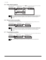
HM-60219-2
Data Setter OPX-2A
AR Series
Built-in Controller Type
OPERATING MANUAL
Thank you for purchasing an Oriental Motor product.
This Operating Manual describes product handling procedures and safety precautions.
• Please read it thoroughly to ensure safe operation.
• Always keep the manual where it is readily available.
Table of contents
1 Safety precautions .............................. 3
2 Introduction ......................................... 4
3 Preparation ......................................... 5
3.1
3.2
3.3
3.4
3.5
3.6
3.7
3.8
Checking the product .............................. 5
Names and functions of parts.................. 5
How to read the display........................... 6
How to read the LED indicators .............. 6
Types of operation modes....................... 6
Basic operations of the OPX-2A ............. 7
Edit lock function ..................................... 8
Rewriting the driver’s non-volatile
memory ................................................... 8
4 Installation and connection of the
OPX-2A .............................................. 9
4.1 Location for installation............................ 9
4.2 Installation method .................................. 9
4.3 Connecting to the driver .......................... 9
5 Screen transitions ............................. 10
6 Monitor mode.................................... 15
6.1 Overview of the monitor mode .............. 15
6.2 Operation in the monitor mode.............. 15
6.3 Monitor items......................................... 16
7 Data mode ........................................ 20
7.1
7.2
7.3
7.4
Operation in the data mode................... 20
Setting items.......................................... 21
Setting example..................................... 22
Initialization of the selected operation
data........................................................ 23
7.5 Initialization of all operation data........... 23
−2−
8 Parameter mode ...............................24
8.1 Operation in the parameter mode ......... 24
8.2 Setting example..................................... 25
8.3 Parameter list ........................................ 26
Operation data................................................26
Parameters......................................................27
8.4 Initializing parameters............................ 32
9 Test mode .........................................33
9.1
9.2
9.3
9.4
9.5
9.6
9.7
9.8
Overview of the test mode..................... 33
Operation in the test mode .................... 34
Direct I/O test......................................... 34
JOG operation ....................................... 35
Data select operation............................. 36
Return-to-home operation ..................... 36
Presetting the position........................... 36
Teaching ................................................ 37
10 Copy mode .......................................38
10.1
10.2
10.3
10.4
10.5
10.6
Overview of the copy mode................... 38
Operation in the copy mode .................. 38
Downloading to the driver...................... 39
Uploading to the OPX-2A...................... 40
Verifying data......................................... 40
Initializing driver data............................. 41
1
Safety precautions
1 Safety precautions
The precautions described below are intended to prevent danger or injury to the user and other personnel through safe,
correct use of the product. Use the product only after carefully reading and fully understanding these instructions.
Also read the “Safety precautions” sections in the operating manuals that came with the product you are combining
with the OPX-2A.
Handling the product without observing the instructions that accompany a “Warning”
symbol may result in serious injury or death.
Handling the product without observing the instructions that accompany a “Caution”
symbol may result in injury or property damage.
Note
The items under this heading contain important handling instructions that the user
should observe to ensure safe use of the product.
General
• Do not use the product in explosive or corrosive environments, in the presence of flammable gases, locations
subjected to splashing water, or near combustibles. Doing so may result in fire, electric shock or injury.
• Assign qualified personnel the task of installing, wiring, operating/controlling, inspecting and troubleshooting the
product. Failure to do so may result in fire, electric shock or injury.
• When the driver’s protection function is triggered, first remove the cause and then clear the protection function.
Continuing the operation without removing the cause of the problem may cause malfunction of the motor and
driver, leading to injury or damage to equipment.
Repair, disassembly and modification
• Do not disassemble or modify the data setter. This may cause electric shock or injury. Refer all such internal
inspections and repairs to the branch or sales office from which you purchased the product.
General
• Do not use the motor and driver beyond their specifications, or electric shock, injury or damage to equipment may
result.
Operation
• Provide an emergency stop device or emergency stop circuit external to the equipment so that the entire equipment
will operate safely in the event of a system failure or malfunction. Failure to do so may result in injury.
Disposal
• To dispose of the data setter, disassemble it into parts and components as much as possible and dispose of
individual parts/components as industrial waste.
−3−
2
Introduction
2 Introduction
Only qualified personnel should work with the product. Use the product correctly after thoroughly reading the section
“1 Safety precautions” on p.3.
The product described in this manual has been designed and manufactured for use in general industrial machinery,
and must not be used for any other purpose. Oriental Motor Co., Ltd. is not responsible for any damage caused
through failure to observe this warning.
Overview of the product
The OPX-2A is a data setter that lets you set operating data and parameters, perform monitoring, etc.
So that the OPX-2A is used correctly and safely, thoroughly read the "AR Series FLEX Built-in Controller type
USER MANUAL" and understand the basic operating procedures and other details of the driver.
Features of OPX-2A
The OPX-2A can be used to save data in addition to setting of operation data and parameters.
There are four destinations (data banks) to save data.
Driver
OPX-2A
Set operation data and
parameters.
Up to 4 sets of operation data
and parameters can be saved.
Driver
Data bank 0
Copy one set
to the driver.
Data bank 1
Data bank 2
Data bank 3
The OPX-2A can be used for the following purposes:
• Set driver operation data and parameters
• Monitor the operating status of the motor
• The data and parameters set in the driver can be saved to the OPX-2A.
• The data and parameters saved in the OPX-2A can be copied to another driver connected to the OPX-2A.
Specifications
Connection
External dimensions
Cable length
Mass
Mini DIN, 8 pins
96(W)× 72(H)× 21.5(D) mm
[3.78 (W) × 2.83 (H) × 0.85 (D) in.]
5 m (16.4 ft.)
0.25 kg (8.8 oz)
Hazardous substances
RoHS (Directive
−4−
2002/95/EC 27Jan.2003) compliant
3
Preparation
3 Preparation
This chapter explains the items you should know before using the OPX-2A.
3.1
Checking the product
Verify that the items listed below are included. Report any missing or damaged items to the branch or sales office
from which you purchased the product.
• Data setter OPX-2A .....................................1 unit
• OPERATING MANUAL (CD-ROM)...........1 pc.
• Information ...................................................1 copy
3.2
Names and functions of parts
Display
This area shows the motor position,
operation data, parameters, alarms, etc.
LED indicators
These LED indicators are used to indicate
the operation mode of the OPX-2A and
the driver status.
Use this button to change the operation
mode or move to the upper level.
Use this button to select data or change
the displayed item or move to the lower
level.
Use these buttons to change the selected item or set data and parameters.
Use these buttons to increase or decrease the value
or change the selected item.
Use these buttons to navigate through each data
or parameter to a desired digit.
Notation
In this manual, keys are denoted by symbols, such as
.
In figures, a simplified illustration of the display and LED indicators is used, as shown below.
−5−
3
Preparation
3.3
How to read the display
The display consists of 7-segment LEDs. (The number “5” and alphabet “S” are the same.)
• Numbers
1
2
3
4
5
6
7
8
9
0
• Alphabets
A
B
C
D
E
F
G
H
I
J
K
L
M
N
O
P
Q
R
S
T
U
V
W
Y
• Signes
+
3.4
-
How to read the LED indicators
When the operation mode is changed or an alarm or warning generates, a corresponding LED will be lit. While the
motor is operating or the edit lock function is enabled, the condition is also indicated by the illumination of a
corresponding LED.
Lit in the parameter mode
Lit in the data mode
Lit in the monitor mode
Lit when an alarm is present
Lit when a warning is present
Lit while the motor is operating
3.5
Lit in the test mode
Lit in the copy mode
Not used
Not used
Not used
Lit when the edit lock function is
enabled
Types of operation modes
The OPX-2A has multiple operation modes. The operation
mode will change every time the
key is pressed. The
display starts in the monitor mode when the power is turned on.
When the operation mode is changed, the LED indicator
corresponding to the previous mode will turn off and the one
corresponding to the new mode will be lit. Identify the current
operation mode based on the LED indicator currently lit.
Monitor mode
(MON)
Copy mode
(COPY)
The mode changes
every time the key
is pressed.
Test mode
(TEST)
−6−
Data mode
(DATA)
Parameter mode
(PAR)
3
3.6
Preparation
Basic operations of the OPX-2A
Use the six keys
to set data and operate the motor.
Operation flow
The OPX-2A is operated according to the flow shown below.
Level 1: Top screen in each mode
1
Level 2: Item selection screen
Level 3
2
Use
to
Use
navigate through
the modes.
to move
to the lower level.
4
Use
to move
to the upper level.
3 Use
to
move to the
previous item.
Use
to
move to the
next item.
1. Use the
key to select a desired operation mode appropriate for your intended operation.
Example: If you want to use a function in the test mode, press the
key to select the test mode (indicated
by a lit “TEST” LED). The top screen of the test mode is displayed.
2. Press the
3. Use the
key to move to the lower level.
keys to select a desired item.
4. To move to the lower level, press the
key. To return to the previous level, press the
key to navigate through the levels and use the
As explained above, use the
desired item. This is the basic operation flow.
Note
key.
keys to select a
If the
key on the OPX-2A is pressed while internal processing is being performed, the top
screen will not change to any of its sub-screens and “mEm-bUSY” will be shown on the display.
Be sure to wait until all internal processing is completed, before pressing the
key.
−7−
3
Preparation
How to input values
As an example, how to change “+30” to “−100” is explained.
Basic operations
• Use the
keys to increase/decrease the value or change the sign.
keys to move to the digit you want to edit.
Use the
• If positive and negative values are differentiated, each value is preceded by a sign.
• You can edit the digit currently blinking.
1. First, change the 10’s place from “3” to “0”.
Press the
key once to move to the 10’s digit you want to edit.
Once
2. Press the
key three times to change the value to “0”.
3 times
3. Next, change the 100’s place from “0” to “1”.
Press the
key once to move to the 100’s digit you want to edit.
Once
4. Press the
key to change the value to “1”.
Once
5. Next, change the sign.
Press the
6. Press the
key once to move to the sign digit you want to edit.
or
Once
key once to change the sign to “−”.
or
7. After all digits have been changed, press the
key to
confirm the value.
All digits comprising the value blink for approx. 2 seconds.
Once
Confirmed
Note
3.7
If the value you have input is outside the setting range, “Error” will be displayed for 1 second.
If this error display appears, input a different value that falls within the setting range.
Edit lock function
Enable the edit lock function if you want to prevent operation data and parameters from being edited or cleared.
Operation data and parameters cannot be changed or deleted while the edit lock function is enabled.
• Setting the edit lock function
In the top screen of each operation mode, press the
key for at least
5 seconds.
The display will show “LocK” and the edit lock function will be enabled.
The “LOCK” LED in the LED indicator area will also be lit.
"LOCK" lit
• Canceling the edit lock function
Again in the top screen of each operation mode, press the
key for at
least 5 seconds.
The display will show “UnLocK” and the edit lock function will be cancelled.
The “LOCK” LED in the LED indicator area will turn off.
3.8
Rewriting the driver’s non-volatile memory
Operation data and parameters are saved to the driver’s non-volatile memory. The non-volatile memory can be
rewritten approx. 100,000 times. The non-volatile memory will be rewritten after one of the following operations is
performed:
• Edit any operation data or parameter
• Download data from the OPX-2A to the driver
• Initialize driver operation data and parameters
−8−
4
Installation and connection of the OPX-2A
4 Installation and connection of the
OPX-2A
4.1
Location for installation
The OPX-2A is designed and manufactured for installation in equipment. Install it in a well-ventilated location that
provides easy access for inspection. The location must also satisfy the following conditions:
•
•
•
•
•
•
•
•
•
•
•
•
4.2
Inside an enclosure that is installed indoors (provide vent holes)
Operating ambient temperature 0 to +40 °C (+32 to +104 °F) (non-freezing)
Operating ambient humidity 85% or less (no condensation)
Area that is free of explosive atmosphere or toxic gas (such as sulfuric gas) or liquid
Area not exposed to direct sun
Area free of excessive amount of dust, iron particles or the like
Area not subject to splashing water (rain, water droplets), oil (oil droplets) or other liquids
Area free of excessive salt
Area not subject to continuous vibration or excessive shocks
Area free of excessive electromagnetic noise (from welders, power machinery, etc.)
Area free of radioactive materials, magnetic fields or vacuum
1000 m (3300 ft.) or less above sea level
Installation method
Using a metal plate of 1 to 3 mm (0.04 to 0.12 in.) in thickness, insert the OPX-2A into the mounting hole from the
front side and securely affix the OPX-2A.
• Dimension of mounting hole [mm (in.)]
(2.68 +0.028
)
0
68 +0.7
0
+0.031
92 +0.8
)
0 (3.62 0
Removing method
Hook
Press all of the four hooks provided on top and bottom of the
OPX-2A. In this condition, press the OPX-2A forward to release.
4.3
Connecting to the driver
Plug the connector attached to the end of the OPX-2A cable
into the data edit connector on the driver, and then turn on the
power to the driver.
∗ Illustration shows ARD-KD.
Note
Driver
Data edit
connector
• When operation data and parameters are set on the OPX-2A, they will be stored in the driver.
Once stored in the driver, the data will not be cleared even after the OPX-2A is disconnected
from the driver.
• Turning on the power to the driver will also turn on the power to the OPX-2A. Turning off the
driver power will turn off the OPX-2A power.
• Turn off the driver power before connecting or disconnecting the OPX-2A cable.
−9−
5
Screen transitions
5 Screen transitions
Top screen
Monitor mode
Command speed
Warning
Command position
Warning record 1
(latest)
Operation number
Warning record 10
(oldest)
Selected number
Clear warning
records
Alarm
Alarm record 1
(latest)
Processing is
in progress
(blinking display)
Direct I/O monitor
Alarm record 10
(oldest)
Input monitor
Clear alarm records
Processing is
in progress
(blinking display)
Absolute position
error alarm reset
Processing is
in progress
(blinking display)
Alarm reset
Processing is
in progress
(blinking display)
−10−
Sensor monitor
Output monitor
5
Note
Screen transitions
• There are the following restrictions while the edit lock function is effective.
· Data mode, parameter mode: Although they are displayed on the screen, they are unable to operate.
· Clearing the alarm and warning records, clear data, position preset, teaching, copy mode: They are not
displayed on the screen.
• When the HMI input is OFF, you can operate all functions of the monitor mode, uploading and verification of
the copy mode, and viewing of the parameter mode.
Data mode
to Parameter mode
Operation data
No.0
Operation data
No.63
Positioning mode
Numerical entry
Writing of data is in progress
(blinking display)
Position
Numerical entry
Writing of data is in progress
(blinking display)
Operating speed
Numerical entry
Writing of data is in progress
(blinking display)
Operating mode
Single
Writing of data is in progress
(blinking display)
Link
Writing of data is in progress
(blinking display)
Link2
Dwell time
Writing of data is
in progress
(blinking display)
Push-motion
Push current
Writing of data is
in progress
(blinking display)
Sequential
positioning
Numerical entry
Writing of data is in progress
(blinking display)
Acceleration
Numerical entry
Writing of data is in progress
(blinking display)
Deceleration
Numerical entry
Writing of data is in progress
(blinking display)
Clear data
Clear
Processing is in progress
(blinking display)
- - - Broken line indicates that data writing cannot be executed
when internal processing is in progress via RS-485 communication.
"mEm-bUSy" is displayed even when the
key is pressed.
In the lower level except the top screen, press the
return to the previous level.
key to
−11−
5
Screen transitions
Parameter mode
Test mode
Parameter selection
(Example: Electronic
gear A)
Direct I/O test
Input test
Parameter setting
Sensor test
Output test
Writing of data is
in progress
(blinking display)
Output test
JOG operation
Operation is in
progress
Data select
operation
Operation data No.
selection 0
Perform positioning
operation
Operation data No.
selection 63
Processing is
in progress
(blinking display)
Perform positioning
operation
Processing is
in progress
(blinking display)
−12−
5
Screen transitions
to Copy mode
Return-to-home
operation
Perform return-tohome operation
Processing is
in progress
(blinking display)
Position preset
Perform position
preset
Processing is
in progress
(blinking display)
Teaching
Perform teaching
Operation data No.
selection 0
Writing of data
is in progress
(blinking display)
Operation data No.
selection 63
Writing of data
is in progress
(blinking display)
- - - Broken line indicates that data writing cannot be executed
when internal processing is in progress via RS-485 communication.
"mEm-bUSy" is displayed even when the
key is pressed.
In the lower level except the top screen, press the
return to the previous level.
key to
−13−
5
Screen transitions
Copy mode
to Monitor mode
Download
Data bank selection 0
Processing is in progress
(blinking display)
Data bank selection 3
Processing is in progress
(blinking display)
Data bank selection 0
Processing is in progress
(blinking display)
Data bank selection 3
Processing is in progress
(blinking display)
Data bank selection 0
Verification result: Matched
Data bank selection 3
Verification result: Unmatched
Upload
Verification
Initialization
Initialize operation data
Processing is in progress
(blinking display)
Initialize parameters
Processing is in progress
(blinking display)
Initialize all data
Processing is in progress
(blinking display)
- - - Broken line indicates that data writing cannot be executed
when internal processing is in progress via RS-485 communication.
"mEm-bUSy" is displayed even when the
key is pressed.
In the lower level except the top screen, press the
return to the previous level.
−14−
key to
6
Monitor mode
6 Monitor mode
6.1
Overview of the monitor mode
• Monitoring the operating status
You can monitor the motor speed, command position, operation data number corresponding to the current operation,
and operation data number currently selected in real time.
• Checking alarms/warnings, clearing alarm/warning records, and resetting alarms
• If an alarm or warning generates, a corresponding alarm code or warning code will be displayed. You can check the
code to identify the details of the alarm/warning.
• Up to ten most recent alarms/warnings can be displayed, starting from the latest one. You can also clear
alarm/warning records.
• You can reset the alarms currently present.
• Checking I/O signals
You can check the ON/OFF status of each I/O signal of the driver.
6.2
Operation in the monitor mode
1. Use the
2. Press the
3. Use the
Top screen of the
monitor mode
key to select the monitor mode.
key in the top screen of the monitor mode.
keys to select the item you want to monitor.
Speed
Command position
Operation number
Selected number
Alarm
Warning
Direct I/O monitor
−15−
6
Monitor mode
6.3
Monitor items
Motor speed
You can check the command speed of the motor (unit: r/min).
While the motor is rotating in the CCW direction, “−” is shown in front of the displayed value. If the speed is
indicated by an absolute value, no sign is shown to indicate the rotating direction. You can select the value display
format using the “display mode of the data setter speed” parameter [ID: 480].
Command position
You can check the command position of the motor with reference to the home position.
If a resolution is set, an appropriate value based on the resolution is shown as steps.
Operation number
You can check the operation data number corresponding to the data used in the current positioning operation.
Selected number
You can check the operation data number currently selected.
Alarm
When an alarm generates, a corresponding alarm code will be displayed.
You can also reset alarms or check and clear alarm records.
Present alarm
Alarm record 1 (latest)
Alarm record 2
Alarm record 10
(oldest)
Clear alarm records
Alarm records are being
cleared (blinking display)
Absolute position error
alarm reset
Alarm is being reset
(blinking display)
Alarm reset
Alarm is being reset
(blinking display)
∗ If operations are limited by the edit lock function, the screen text in gray is not shown.
Note
• Do not turn off the driver power while an alarm is being reset or alarm records are being
cleared (=while the display is blinking). Doing so may damage the data.
• Some alarms cannot be reset on the OPX-2A. Check by the following table. To reset these
alarms, you must cycle the driver power.
−16−
6
Monitor mode
• Alarm code list
Code
Alarm name
10
20
21
Excessive position deviation
Excessive position deviation during
current OFF
Overcurrent∗1
Main circuit overheat
22
Overvoltage
12
Resetting on the OPX-2A
Number of times the
driver’s ALARM LED blinks
Possible
4
Not possible
Possible
ARD-KD: Possible
ARD-AD, ARD-CD: Not possible
5
2
3
23
Main power off∗1
Possible
25
Undervoltage
27
Backup battery undervoltage
7
28
Sensor error
8
Not possible
29
CPU peripheral circuit error
9
2D
Main circuit output error ∗1
5
30
Overload
Possible
2
31
Overspeed
33
Absolute position error
Possible∗2
7
34
Command pulse error
Possible
2
41
EEPROM error
9
42
Initial sensor error
Not possible
8
43
Initial rotor rotation error
45
Motor combination error
4A
Return-to-home incomplete
Possible
7
51
Regeneration unit overheat ∗1
Not possible
2
60
±LS both sides active
61
Reverse limit sensor connection
62
Home seeking error
63
No HOMES
Possible
64
TIM, Z, SLIT input error
66
Overtravel
67
Software overtravel
6A
Home seeking offset error
7
70
Invalid operation data
71
Electronic gear setting error
Not possible
72
Wrap setting error
81
Network bus error
Possible
83
Communication switch setting error
Not possible
84
RS-485 communication error
Possible
85
RS-485 communication timeout
8E
Network converter error
F0
CPU error
Not possible
Lit
∗1 ARD-AD and ARD-CD only.
∗2 This alarm cannot be released by the "alarm reset (AL-rSt)." Release the alarm by the "absolute position error alarm
reset (AL33-rSt)."
−17−
6
Monitor mode
• How to reset an alarm
1. While an alarm is displayed, press the
2. Press the
key to move to the lower level.
key to select the alarm reset screen.
3. Press the
key.
The alarm is reset.
• How to reset an absolute position error
1. While an alarm is displayed, press the
2. Press the
key to move to the lower level.
key twice to select the absolute position error alarm reset screen.
3. Press the
key.
The absolute position error alarm is reset.
• How to check an alarm record
You can check up to ten most recent alarms, starting from the latest one.
1. While an alarm is displayed, press the
key to move to the lower level.
The latest alarm is displayed.
2. Press the
key.
The second latest alarm is displayed.
3. Every time the
key is pressed, the next older alarm will be displayed. Use the
select the alarm record you want to check.
keys to
• How to clear all alarm records
You can clear all alarm records at once.
1. While an alarm is displayed, press the
2. Press the
key to move to the lower level.
key three times and select the alarm record clear screen.
3. Press the
key.
All alarm records are cleared.
Warning
When a warning generates, a corresponding warning code will be displayed.
You can also check or clear warning records.
Present warning
Warning record 1
(latest)
Warning record 2
Warning record 10
(oldest)
Clear warning records
Warning records are being
cleared (blinking display)
∗ If operations are limited by the edit lock function, the screen text in gray is not shown.
Note
• Do not turn off the driver power while warning records are being cleared (=while the display is
blinking). Doing so may damage the data.
• You can also clear the warning records by turning off the driver power.
−18−
6
Monitor mode
• Warning code list
Code
10
12
21
22
25
30
Warning name
Excessive position deviation
Excessive position deviation during current OFF
Main circuit overheat
Overvoltage
Undervoltage
Overload
Code
31
48
71
72
84
Warning name
Overspeed
Battery connection error
Electronic gear setting error
Wrap setting error
RS-485 communication error
• How to check a warning record
You can check up to ten most recent warnings, starting from the latest one.
1. While a warning is displayed, press the
key to move to the lower level.
The latest warning is displayed.
2. Press the
key.
The second latest warning is displayed.
3. Every time the
key is pressed, the next older warning will be displayed. Use the
to select the warning record you want to check.
keys
• How to clear all warning records
You can clear all warning records at once.
1. While a warning is displayed, press the
2. Press the
key to move to the lower level.
key and select the warning record clear screen.
3. Press the
key.
All warning records are cleared.
Direct I/O monitor
You can check the ON/OFF status of each I/O signal of the driver.
Top screen of the
direct I/O monitor
Input monitor
Sensor monitor
Output monitor
Each digit on the 7-segment LED display corresponds to a signal. If the signal is ON, the corresponding digit is lit. If
the signal is OFF, the digit is unlit.
• Input signals
• Output signals
Output monitor
Input monitor
Sensor monitor
IN0
IN1
IN2
IN3
IN4
IN5
IN6
IN7
OUT0
OUT1
OUT2
OUT3
OUT4
OUT5
+LS
-LS
HOMES
SLIT
−19−
7
Data mode
7 Data mode
Up to 64 sets of motor operation data can be set. Once set, the operation data is stored in the driver. The data will not
be lost even after the OPX-2A is disconnected from the driver.
Before setting operation data, read the "AR Series FLEX Built-in Controller type USER MANUAL" carefully to
understand the basic operations, functions and other details of the driver.
Note
• Operation data has significant bearing on motor operation. Before setting any operation data,
make sure you fully understand the content of the operation data.
• If operations are limited by the edit lock function or HMI input, operation data cannot be edited.
• Operation data can also be set by selecting the ID with the parameter mode.
• If the value you have input is outside the setting range, “Error” will be displayed for 1 second.
If this error display appears, input a different value that falls within the setting range.
• If
key is pressed while executing the internal processing via RS-485 communication,
"mEm-bUSy" may be displayed. Check “5 Screen transitions” on p.10 when "mEm-bUSy" is
displayed. Be sure to wait until all internal processing is completed, before pressing the
key.
7.1
Operation in the data mode
1. Use the
2. Press the
key to select the data mode.
key on the top screen of the data mode.
3. Use the
keys to select a desired operation data number.
4. Press the
key.
The display changes to the operation data screen.
5. Use the
key to select the operation data item you want to set.
6. When pressing the
key on the last operation data item, the display returns to the operation data
No. screen.
Top screen of
the data mode
Operation data
No. selection 0
Operation data
No. selection 1
Positioning mode
Position
Operating speed
Operating mode
Sequential
positioning
Acceleration
Deceleration
Operation data
No. selection 62
Clear data
Operation data
No. selection 63
∗ If operations are limited by the edit lock function, the screen text in gray is not shown.
−20−
7
7.2
Data mode
Setting items
When a data has been changed, the new data will become effective after stopping the operation.
Setting item
Setting range
Initial value
Positioning mode
0: Incremental mode
1: Absolute mode
0
Position
−8,388,608 to
+8,388,607 step
0
Operating speed
1 to 1,000,000 Hz
Operating mode
Sequential
positioning
0: Single
1: Link
2: Link2
3: Push-motion
0: Disable
1: Enable
1000
0
Description
Selects how to specify the position (travel amount)
in positioning operation (absolute mode or
incremental mode).
Sets the position (distance) for positioning
operation.
Sets the operating speed in positioning operation
and continuous operation.
Sets perform positioning operation as
single-motion, linked-motion or push-motion
operation.
Sets enable or disable sequential positioning
operation.
Sets the acceleration rate in positioning operation
Acceleration
and continuous operation.∗
0.001 to 1000.000
1.000
(ms/kHz or s)
Sets the deceleration rate in positioning operation
Deceleration
and continuous operation.∗
Push current
0.0 to 50.0%
20.0
Sets the current value of push-motion operation.
Sets the dwell time to be used in linked-motion
Dwell time
0.000 to 50.000 s
0.000
operation 2.
∗ This item is effective when the “acceleration (deceleration) rate type” parameter [ID: 326] is set to “separate”.
If this parameter is set to “common”, the values of the “common acceleration rate” [ID: 320] and “common deceleration
rate” [ID: 321] parameters will be used.
0
How to set the dwell time
When displaying the "Link2" on the "operating mode" and pressing the
key, the screen to set the dwell time
keys and press the
key.
is displayed. Input the dwell time using the
Operating mode
Single
Pushmotion
Link2
Dwell time
Processing is in progress
(blinking display)
Link
−21−
7
Data mode
7.3
Setting example
This section explains how to change the the positioning mode and position of the operation data No.0.
• Positioning mode: Changes from incremental mode to absolute mode.
• Position: Changes from 0 step to 10000 steps.
1. Use the
key to select the data mode.
The “DATA” LED is lit.
Top screen of the data mode
Operation data No.0
2. Press the
key on the top screen of the data mode.
The display changes to the operation data No.0 screen.
Positioning mode
3. Press the
key.
The display changes to the positioning mode screen.
Present value of the positioning mode
(blinking display)
4. Press the
key again.
The present set value of the positioning mode is displayed with
blinking.
Change to absolute mode
(blinking display)
5. Press the
key once to select “AbS.”
Confirm the changed value (quick blinking)
6. Press the
key.
The blinking speed of the input value becomes quickly and the
value is set.
The display returns to the positioning mode screen.
Return to the positioning mode
7. Press the
key.
The display changes to the position screen.
Position
8. Press the
key.
The present set value of the position is displayed with blinking.
9. Use the
keys to select “10000”.
The selected digit is displayed with blinking.
Present value of the position
(blinking display)
to navigate
Use
through the digits.
Use
to increase/
decrease the value.
Input 10000 (blinking display)
10. Press the
key.
The blinking speed of the input value becomes quickly and the
value is set.
The display returns to the position screen.
Confirm the changed value (quick blinking)
Return to the position
11. Press the
key.
The display returns to the operation data No.0 screen.
−22−
Return to the operation data No.0
7
7.4
Data mode
Initialization of the selected operation data
All of the set value for the selected operation data number can be reverted to the initial values.
1. Use the
key to select the data mode.
The “DATA” LED is lit.
Top screen of the data mode
Operation data No.0
2. Press the
key on the top screen of the data mode.
The display changes to the operation data No.0 screen.
Positioning mode
3. Press the
key.
The display changes to the positioning mode screen.
Once
Clear data
4. Press the
key once.
The display changes to the clear data screen.
Clear
5. Press the
key.
The display changes to the screen to execute clearing.
6. Press the
key.
The display blinks and the operation data No.0 is cleared.
7.5
Processing is in progress
(blinking display)
Initialization of all operation data
All of the operation data saved in the driver can be reverted to the initial values. Perform "Initialize operation data" of
the copy mode.
For the operation, check the screen transitions of the copy mode on p.14, or "10.6 Initializing driver data" on p.41.
−23−
8
Parameter mode
8 Parameter mode
You can set parameters relating to motor operation and control. These parameters are saved in the driver.
Before setting parameters, read the "AR Series FLEX Built-in Controller type USER MANUAL" carefully to
understand the basic operations, functions and other details of the driver.
Note
• Parameters have significant bearing on motor operation. Before setting any parameter, make
sure you fully understand the content of the parameter.
• If operations are limited by the edit lock function or HMI input, parameters cannot be edited.
• If the value you have input is outside the setting range, “Error” will be displayed for 1 second.
If this error display appears, input a different value that falls within the setting range.
• If
key is pressed while executing the internal processing via RS-485 communication,
"mEm-bUSy" may be displayed. Check “5 Screen transitions” on p.10 when "mEm-bUSy" is
displayed. Be sure to wait until all internal processing is completed, before pressing the
key.
• If a nonexistent parameter ID is entered, "id-Error" will be displayed for 1 second. Check the ID
and enter the correct one.
Timing for the setting value to become effective
When a parameter is changed, the timing for the new value to become effective varies depending on the parameters,
which are the following four types.
• Effective immediately
Executes the recalculation and setup immediately when writing the parameter.
• Effective after stopping the operation
Executes the recalculation and setup after stopping the operation.
• Effective after executing the configuration
Executes the recalculation and setup after executing the configuration.
• Effective after turning the power ON again
Executes the recalculation and setup after turning the power ON again.
8.1
Operation in the parameter mode
1. Use the
2. Press the
3. Use the
key to select the parameter mode.
key on the top screen of the parameter mode.
keys to enter the parameter ID.
4. Press the
key.
The display changes to the parameter setting screen.
5. Use the
Top screen of the
parameter mode
−24−
keys to enter the value.
Parameter selection
(Example: Electronic
gear A)
Parameter setting
8
8.2
Parameter mode
Setting example
This section explains how to assign the TIM output to the OUT1 output.
1. Use the
key to select the parameter mode.
The “PAR” LED is lit.
Top screen of the parameter mode
Select parameter
2. Press the
key on the top screen of the parameter
mode.
Use
to navigate
through the digits.
Use
to increase/
decrease the value.
OUT1 output function selection
(ID: 2209)
3. Use the
keys to enter [ID: 2209] in the
"OUT1 output function selection" parameter.
Present value (blinking display)
4. Press the
key.
The present set value of the OUT1 output is displayed with blinking.
to navigate
Use
through the digits.
Use
to increase/
decrease the value.
Set the OUT1 output to "72"
(blinking display)
5. Use the
keys to enter “72”.
“72” indicates the TIM output.
Confirm the value (quick blinking)
6. Press the
key.
The blinking speed of the input value becomes quickly and the value
is set.
The display returns to the OUT1 signal mode selection parameter
screen.
Return to the "OUT1 output function
selection" parameter
−25−
8
Parameter mode
8.3
Parameter list
There is an unique ID in each parameter. With the OPX-2A, set the parameter selecting the ID.
Operation data
Operation data can also be set by selecting the data mode.
Executes the recalculation and setup after changing the operation data.
ID
640
to
703
512
to
575
576
to
639
Parameter name
Positioning mode No.0
to
Positioning mode No.63
Position No.0
to
Position No.63
Operating speed No.0
to
Operating speed No.63
Description
Selects how to specify the position (travel
amount) in positioning operation (absolute
mode or incremental mode).
704
to
767
Operating mode No.0
to
Operating mode No.63
Setting range
Initial value
0: Incremental mode
1: Absolute mode
0
Sets the position (distance) for positioning
operation.
−8,388,608 to
+8,388,607 step
0
Sets the operating speed in positioning
operation and continuous operation.
0 to 1,000,000 Hz
Sets perform positioning operation as
single-motion, linked-motion or
push-motion operation.
0: Single
1: Link
2: Link2
3: Push-motion
1000
0
960
Sequential positioning No.0
Sets whether to enable or disable
0: Disable
0
to
to
sequential positioning operation.
1: Enable
1023
Sequential positioning No.63
768
Acceleration No.0
Sets the acceleration rate in positioning
to
to
operation and continuous operation.∗
831
Acceleration No.63
0.001 to 1000.000
1.000
(ms/kHz or s)
832
Deceleration No.0
Sets the deceleration rate in positioning
to
to
operation and continuous operation.∗
895
Deceleration No.63
896
Push current No.0
Sets the current value of push-motion
0.0 to 50.0%
20.0
to
to
operation.
959
Push current No.63
1024
Dwell time No.0
Sets the dwell time to be used in
to
to
0.000 to 50.000 s
0.000
linked-motion operation 2.
1087
Dwell time No.63
∗ This item is effective when the “acceleration (deceleration) rate type” parameter [ID: 326] is set to “separate”.
If this parameter is set to “common”, the values of the “common acceleration rate” [ID: 320] and “common deceleration rate” [ID: 321]
parameters will be used.
−26−
8
Parameter mode
Parameters
ID
Parameter name
256
STOP input action
257
Hardware overtravel
258
Overtravel action
259
260
Positioning
completion signal
range
Positioning
completion signal
offset
AREA1 positive
direction position
AREA1 negative
direction position
AREA2 positive
direction position
AREA2 negative
direction position
AREA3 positive
direction position
AREA3 negative
direction position
Minimum ON time
for MOVE output
LS logic level
HOMES logic level
SLIT logic level
Description
Setting range
0: Immediate stop
1: Deceleration stop
Sets how the motor should stop when a 2: Immediate stop &
STOP input is turned ON.
Current OFF
3: Deceleration stop &
Current OFF
Sets whether to enable or disable
0: Disable
hardware overtravel detection using
1: Enable
±LS inputs.
Sets the motor action to take place
0: Immediate stop
upon the occurrence of overtravel.
1: Deceleration stop
Sets the output range of the END
signal (the motor operation converges
0.0 to 18.0°
within this angular range).
Sets the offset for the END signal (the
offset for converging angular range).
−1.8 to 1.8°
Initial value
1
1
0
1.8
0.0
Sets the position of AREA1 positive
direction.
Sets the position of AREA1 negative
262
direction.
Sets the position of AREA2 positive
263
direction.
−8,388,608 to
0
8,388,607 step
Sets the position of AREA2 negative
264
direction.
Sets the position of AREA3 positive
265
direction.
Sets the position of AREA3 negative
266
direction.
Sets the minimum time during which
267
0 to 255 ms
0
the MOVE output remains ON
268
Sets the±LS input logic.
0: Normally open
0
269
Sets the HOMES input logic.
1: Normally closed
270
Sets the SLIT input logic.
Sets the motor operating current based
288
RUN current
0.0 to 100.0%
100.0
on the rated current being 100%.
Sets the motor standstill current as a
289
STOP current
percentage of the rated current, based 0.0 to 50.0%
50.0
on the rated current being 100%.
Adjusts the motor response in reaction
290
Position loop gain
1 to 50
10
to the position deviation.
Adjusts the motor response in reaction
291
Speed loop gain
10 to 200
180
to the speed deviation.
Sets the decreases the deviation that
Speed loop integral
cannot be adjusted with the speed loop 10.0 to 200.0 ms
292
100.0
time constant
gain.
293
Speed filter
Adjusts the motor response.
0 to 200 ms
1
Moving average
Sets the time constant for the moving
294
1 to 200 ms
1
time
average filter.
Sets the common acceleration (rate or
Common
time) in positioning operation and
320
acceleration
continuous operation.
0.001 to 1000.000
1.000
Sest the common deceleration (rate or (ms/kHz or s)
Common
time) in positioning operation and
321
deceleration
continuous operation.
Sets the starting speed in positioning
operation and continuous operation.
322
Starting speed
The motor will operate at the starting
0 to 1,000,000 Hz
500
speed if the operating speed is below
the starting speed.
∗ Indicates the timing for the data to become effective. (A: Effective immediately, B: Effective after stopping the operation,
C: Effective after executing the configuration)
261
Effective∗
A
C
A
B
−27−
8
Parameter mode
ID
323
324
325
326
327
352
353
354
355
356
357
358
Parameter name
JOG operation
speed
Acceleration/deceler
ation of JOG
Description
Sets the operating speed for JOG
operation.
Sets the acceleration/deceleration (rate
or time) for JOG operation.
Sets the starting speed for JOG
JOG starting speed
operation.
Sets whether to use the common
Acceleration/deceler acceleration/ deceleration or the
ation type
acceleration/deceleration specified for
the operation data.
Acceleration/deceler
Sets the acceleration/deceleration unit.
ation unit
Home-seeking
mode
Sets the mode for return-to-home
operation.
Operation speed of
home-seeking
Acceleration/deceler
ation of
home-seeking
Starting speed of
home-seeking
Position offset of
home-seeking
Starting direction of
home-seeking
Sets the operating speed for
return-to-home operation.
Sets the acceleration/ deceleration
(rate or time) for return-to-home
operation.
Sets the starting speed for
return-to-home operation.
Sets the amount of offset from
mechanical home.
Sets the starting direction for home
detection.
Sets whether or not to concurrently use
the SLIT input for return-to-home
operation.
Sets whether or not to concurrently use
the TIM signal for return-to-home
operation.
Sets the operating current for
push-motion return-to-home operation
based on the rated current being
100%.
Sets the condition in which an overload
alarm generates.
Sets the condition that an excessive
position deviation alarm generates
when the motor is in a state of current
ON.
Sets whether to enable or disable
return-to-home incomplete alarm
Sets the temperature at which a main
circuit overheat warning generates.
Sets the condition that an overload
warning generates.
Sets the condition that an overspeed
warning generates.
SLIT detection with
home-seeking
359
TIM signal detection
with home-seeking
360
Operation current of
push-motion
home-seeking
384
Overload alarm
385
Overflow rotation
alarm during current
ON
388
Return-to-home
incomplete alarm
416
Overheat warning
417
Overload warning
418
Overspeed warning
419
Overvoltage warning
Sets the voltage at which an
overvoltage warning generates.
420
Undervoltage
warning
Sets the voltage at which an
undervoltage warning generates.
Setting range
Initial value
1 to 1,000,000 Hz
1000
0.001 to 1000.000
(ms/kHz or s)
1.000
0 to 1,000,000 Hz
500
0: Common
1: Separate
0: ms/kHz
1: s
0: 2-sensor mode
1: 3-sensor mode
2: Push mode
0
0.001 to 1000.000
(ms/kHz or s)
1.000
1 to 1,000,000 Hz
500
0.0 to 100.0%
0
B
1
0
100.0
0.1 to 30.0 s
5.0
0.01 to 300.00 rev
3.00
A
0: Disable
1: Enable
40 to 85 °C
(104 to 185 °F)
0.1 to 30.0 s
0
−28−
C
85
5.0
1 to 5000 r/min
4500
ARD-KD: 15.0 to 63.0 V
ARD-AD, ARD-CD:
120 to 450 V
ARD-KD: 15.0 to 63.0 V
ARD-AD, ARD-CD:
120 to 280 V
63.0
435
18.0
120
Setse the condition that an excessive
position deviation warning generates
0.01 to 300.00 rev
3.00
421
when the motor is in a state of current
ON.
∗ Indicates the timing for the data to become effective. (A: Effective immediately, B: Effective after stopping the operation,
C: Effective after executing the configuration)
Overflow rotation
warning during
current ON
C
1
1000
0: Disable
1: Enable
B
1
1 to 1,000,000 Hz
−8,388,608 to 8,388,607
step
0: Negative direction
1: Positive direction
Effective∗
A
8
ID
448
449
Parameter name
Electronic gear A
Electronic gear B
Description
Sets the denominator of electric gear.
Sets the numerator of electric gear.
450
Motor rotation
direction
Sets the rotation direction of motor
output shaft.
451
Software overtravel
454
Positive software
limit
Negative software
limit
Preset position
455
Wrap setting
456
Wrap setting range
Data setter speed
display
Absolute-position
backup system
MS0 operation No.
selection
MS1 operation No.
selection
MS2 operation No.
selection
MS3 operation No.
selection
MS4 operation No.
selection
MS5 operation No.
selection
452
453
480
482
2048
2049
2050
2051
2052
2053
Sets whether to enable or disable
software overtravel detection using soft
limits.
Sets the value of soft limit in positive
direction.
Sets the value of soft limit in negative
direction.
Sets the preset position.
Sets whether to enable or disable wrap
function.
Sets the wrap setting range.
Sets the display method of the speed
monitor for the OPX-2A.
Sets whether to enable or disable
absolute-position backup system.
Sets the operation data No.
corresponding to MS0 to MS5 input.
2065
2066
Speed error gain 2
2067
Control mode
2068
Smooth driver
2081
2082
0: Positive direction
=CCW
1: Positive direction
=CW
1
0: Disable
1: Enable
1
C
8,388,607
−8,388,608 to
8,388,607 step
A
−8,388,608
0
0: Disable
1: Enable
1 to 8,388,607 step
0: Signed
1: Absolute value
0: Disable
1: Enable
0
C
1000
0
A
0
C
2
0 to 63
B
3
5
Sets whether to enable or disable
moving average.
Sets the filter function to adjust the
motor response.
Adjusts vibration during operation.
Adjusts vibration during acceleration/
deceleration.
Automatic return
action
Operation speed of
automatic return
Acceleration/deceler
ation of automatic
return
Starting speed of
automatic return
1
4
ARD-KD:
Moving average
ARD-AD, ARD-CD:
Filter selection
Speed error gain 1
2080
1 to 65535
Effective∗
1
Sets the timing to output the HOME-P
output.
2064
Initial value
0
HOME-P function
selection
2054
Setting range
Parameter mode
Sets the control mode of the driver.
Sets whether to enable or disable
smooth drive function.
Sets whether to enable or disable
automatic return operation.
Sets the operating speed for automatic
return operation.
0: Home output
1: Return-to-home
complete output
0: Disable
1: Enable
0: Speed filter
1: Moving average
0
0
C
0
0 to 500
45
0: Normal mode
1: Current control mode
0
0: Disable
1: Enable
A
1
A
C
0
1 to 1,000,000 Hz
1000
Sets the acceleration/deceleration (rate 0.001 to 1000.000
or time) for automatic return operation. (ms/kHz or s)
1.000
B
Sets the starting speed for automatic
2083
0 to 1,000,000 Hz
500
return operation.
Sets the travel amount for JOG
2084
JOG travel amount
1 to 8,388,607 step
1
operation.
∗ Indicates the timing for the data to become effective. (A: Effective immediately, B: Effective after stopping the operation,
C: Effective after executing the configuration)
−29−
8
Parameter mode
ID
Parameter name
2112
Overflow rotation
alarm during current
OFF
Description
Sets the condition that an excessive
position deviation alarm generates
when the motor is in a state of current
OFF.
Setting range
0.01 to 300.00 rev
Initial value
Effective∗
100.00
A
IN0 input function
3
selection
IN1 input function
2177
4
selection
IN2 input function
2178
48
selection
IN3 input function
2179
49
selection
Sets the function of input terminals IN0
See table on p.32.
to IN7.
IN4 input function
2180
50
selection
IN5 input function
2181
16
selection
IN6 input function
2182
18
selection
IN7 input function
2183
24
selection
IN0 input logic level
2192
setting
IN1 input logic level
2193
setting
IN2 input logic level
2194
setting
IN3 input logic level
2195
setting
0: Normally open
Sets the IN0 to IN7 input logic.
0
1: Normally closed
IN4 input logic level
2196
setting
IN5 input logic level
2197
setting
IN6 input logic level
2198
setting
IN7 input logic level
2199
setting
OUT0 output
2208
70
function selection
OUT1 output
2209
69
function selection
OUT2 output
2210
73
function selection
Sets the function of output terminals
See table on p.32.
OUT0 to OUT5.
OUT3 output
2211
67
function selection
OUT4 output
2212
66
function selection
OUT5 output
2213
65
function selection
NET-IN0 input
2224
48
function selection
NET-IN1 input
2225
49
function selection
NET-IN2 input
2226
50
function selection
Sets the function of NET-IN0 to
NET-IN3 input
See table on p.32.
2227
4
NET-IN6.
function selection
NET-IN4 input
2228
3
function selection
NET-IN5 input
2229
18
function selection
NET-IN6 input
2230
16
function selection
∗ Indicates the timing for the data to become effective. (A: Effective immediately, C: Effective after executing the configuration)
2176
−30−
C
8
ID
2231
2232
2233
2234
2235
2236
2237
2238
2239
2240
2241
2242
2243
2244
2245
2246
2247
2248
2249
2250
2251
2252
2253
2254
2255
Parameter name
NET-IN7 input
function selection
NET-IN8 input
function selection
NET-IN9 input
function selection
NET-IN10 input
function selection
NET-IN11 input
function selection
NET-IN12 input
function selection
NET-IN13 input
function selection
NET-IN14 input
function selection
NET-IN15 input
function selection
NET-OUT0 output
function selection
NET-OUT1 output
function selection
NET-OUT2 output
function selection
NET-OUT3 output
function selection
NET-OUT4 output
function selection
NET-OUT5 output
function selection
NET-OUT6 output
function selection
NET-OUT7 output
function selection
NET-OUT8 output
function selection
NET-OUT9 output
function selection
NET-OUT10 output
function selection
NET-OUT11 output
function selection
NET-OUT12 output
function selection
NET-OUT13 output
function selection
NET-OUT14 output
function selection
NET-OUT15 output
function selection
Description
Setting range
Parameter mode
Initial value
0
8
9
10
Sets the function of NET-IN7 to
NET-IN15.
See table on p.32.
5
6
7
1
2
48
49
50
4
C
70
67
66
Sets the function of NET-OUT0 to
NET-OUT15.
65
See table on p.32.
80
73
74
75
72
68
69
71
2304
Communication
timeout
2305
Communication
error alarm
Sets the condition in which a
communication timeout occurs in
RS-485 communication.
Sets the condition in which a RS-485
communication error alarm generates.
2563
Communication
parity
Sets the parity of RS-485
communication.
0: Not monitored
0 to 10000 ms
0
1 to 10 times
3
0: None
1: Even number
2: Odd number
0: 1 bit
1: 2 bit
A
1
Communication stop Sets the stop bit of RS-485
0
bit
communication.
Transmission
Sets the transmission waiting time of
2565
0.0 to 1000.0 ms
10.0
waiting time
RS-485 communication.
∗ Indicates the timing for the data to become effective. (A: Effective immediately, C: Effective after executing the configuration,
D: Effective after turning the power ON again)
2564
Effective∗
D
−31−
8
Parameter mode
Setting range of function selection parameters
• IN input function selection parameters
0: Not used
1: FWD
2: RVS
3: HOME
4: START
5: SSTART
6: +JOG
7: −JOG
8: MS0
9: MS1
10: MS2
11: MS3
12: MS4
13: MS5
16: FREE
17: C-ON
18: STOP
24: ALM-RST
25: P-PRESET
26: P-CLR
27: HMI
32: R0
33: R1
34: R2
35: R3
36: R4
37: R5
38: R6
39: R7
40: R8
41: R9
42: R10
43: R11
44: R12
45: R13
46: R14
47: R15
48: M0
49: M1
50: M2
45: R13
46: R14
47: R15
48: M0_R
49: M1_R
50: M2_R
51: M3_R
52: M4_R
53: M5_R
60: +LS_R
61: −LS_R
72: TIM
62: HOMES_R
73: AREA1
63: SLIT_R
74: AREA2
65: ALM
75: AREA3
66: WNG
80: S-BSY
67: READY
82: MPS∗
68: MOVE
69: END
70: HOME-P
71: TLC
∗ ARD-AD and ARD-CD only.
35: R3
36: R4
37: R5
38: R6
39: R7
40: R8
41: R9
42: R10
43: R11
44: R12
45: R13
46: R14
47: R15
48: M0
45: R13
46: R14
47: R15
48: M0_R
49: M1_R
50: M2_R
51: M3_R
52: M4_R
53: M5_R
60: +LS_R
61: −LS_R
72: TIM
62: HOMES_R
73: AREA1
63: SLIT_R
74: AREA2
65: ALM
75: AREA3
66: WNG
80: S-BSY
67: READY
82: MPS∗
68: MOVE
69: END
70: HOME-P
71: TLC
∗ ARD-AD and ARD-CD only.
51: M3
52: M4
53: M5
• OUT output function selection parameters
0: Not used
1: FWD_R
2: RVS_R
3: HOME_R
4: START_R
5: SSTART_R
6: +JOG_R
7: −JOG_R
8: MS0_R
9: MS1_R
10: MS2_R
11: MS3_R
12: MS4_R
13: MS5_R
16: FREE_R
17: C-ON_R
18: STOP_R
32: R0
33: R1
34: R2
35: R3
36: R4
37: R5
38: R6
39: R7
40: R8
41: R9
42: R10
43: R11
44: R12
• NET-IN input function selection parameters
0: Not used
1: FWD
2: RVS
3: HOME
4: START
5: SSTART
6: +JOG
7: −JOG
8: MS0
9: MS1
10: MS2
11: MS3
12: MS4
13: MS5
16: FREE
17: C-ON
18: STOP
27: HMI
32: R0
33: R1
34: R2
49: M1
50: M2
51: M3
52: M4
53: M5
• NET-OUT output function selection parameters
0: Not used
1: FWD_R
2: RVS_R
3: HOME_R
4: START_R
5: SSTART_R
6: +JOG_R
7: −JOG_R
8: MS0_R
9: MS1_R
8.4
10: MS2_R
11: MS3_R
12: MS4_R
13: MS5_R
16: FREE_R
17: C-ON_R
18: STOP_R
32: R0
33: R1
34: R2
35: R3
36: R4
37: R5
38: R6
39: R7
40: R8
41: R9
42: R10
43: R11
44: R12
Initializing parameters
You can revert parameters saved in the driver to their initial values. Perform "Initialize operation data" of the copy
mode. For the operation, check the screen transitions of the copy mode on p.14, or "10.6 Initializing driver data" on
p.41.
−32−
9
Test mode
9 Test mode
9.1
Overview of the test mode
• Direct I/O test
You can check the ON/OFF status of each input signal of the driver. You can also switch the ON/OFF status of each
output signal on the OPX-2A. There is also a direct I/O test function with which you can check the connection status
of the driver.
• JOG operation
You can operate the motor using the keys on the OPX-2A.
• Data select operation
You can perform the positioning operation.
• Return-to-home operation
You can perform the return-to-home operation.
• Position preset
You can set the preset value as the command position.
• Teaching
You can operate the motor using the keys on the OPX-2A and reflect the attained position in the operation data.
Note
• Stop the motor operation before changing to the test mode.
• When you move from the top screen of the test mode to a lower level, the following inputs will
•
•
•
•
be disabled.
START, SSTART, HOME, ±JOG, FWD, RVS and MS0 to MS5.
In the direct I/O test, if the screen moves to the lower level, all of I/O signals and operation will
be disabled.
If the
key is pressed while executing the internal processing via RS-485
communication, "mEm-bUSy" may be displayed. Check “5 Screen transitions” on p.10 when
"mEm-bUSy" is displayed. Be sure to wait until all internal processing is completed, before
pressing the
key.
If "Error" is displayed when data select operation, return-to-home operation, position preset or
teaching function is performed, check whether an alarm generates.
When the HMI input is OFF, test mode cannot be executed.
−33−
9
Test mode
9.2
Operation in the test mode
1. Use the
key to select the test mode.
2. Press the
key in the top screen of the test mode.
The display changes to the test mode item screen.
3. Use the
Top screen of
the test mode
keys to select the item you want to perform.
Direct I/O test
JOG operation
Data select
operation
Return-to-home
operation
Position preset
Teaching
∗ If operations are limited by the edit lock function, the screen text in gray is not shown.
• What happens when the
key is pressed while the motor is operating
While the motor is operating, you cannot move to any lower level from the top screen of the
key will generate an error, and “oPE-Err” will be shown.
test mode. Pressing the
Be sure to stop the motor operation before pressing the
key.
9.3
Direct I/O test
When checking the connection condition of the driver, perform the direct I/O test.
Top screen of the
direct I/O test
Input test
Sensor test
Output test
−34−
9
Test mode
Each digit on the 7-segment LED display corresponds to a signal. The LED is lit when the input signal is ON, and it
is unlit when the input signal is OFF.
keys to switch the ON-OFF state of the output signal. " " is displayed when the signal is ON,
Use the
while " " is displayed when the signal is OFF.
• Input signals
• Output signals
Input test
Output test
IN0
IN1
IN2
IN3
IN4
IN5
IN6
IN7
Sensor test
OUT0
OUT1
OUT2
OUT3
OUT4
OUT5
Use
to navigate through the digits.
Use
to switch the ON/OFF status.
indicates the ON status.
+LS
-LS
HOMES
SLIT
9.4
indicates the OFF status.
JOG operation
You can operate the motor using the keys on the OPX-2A.
Top screen of
JOG operation
Operation is in
progress
Pressing the
key once causes the motor to rotate one step in the positive direction. Pressing and holding the
key causes the motor to rotate continuously in the positive direction.
Pressing the
key once causes the motor to rotate one step in the negative direction. Pressing and holding the
key causes the motor to rotate continuously in the negative direction.
The operating speed corresponds to the value set in the “JOG operating speed” parameter [ID: 323].
Take note that when the value set in the “JOG starting speed” parameter [ID: 325] is greater than the value set in the
“JOG operating speed” parameter [ID: 323], the Jog starting speed will become effective.
Speed
VR
TR
VS
1step
LEss than 1 s
1step
1 s or more
TR
VS: JOG starting speed (ID: 325)
VR: JOG operating speed (ID: 323)
TR: Acceleration/deceleration of JOG (ID: 324)
Time
Key
Note
During operation, the motor rotates at the specified operating speed while each applicable key is
pressed. Before commencing the operation, consider the status of the equipment and condition
of its surroundings to confirm thoroughly that motor rotation will not cause any dangerous
situations.
−35−
9
Test mode
9.5
Data select operation
Select a desired operation data number and then press the
Top screen of data
select operation
Operation data No.
selection 0
key, and positioning operation will be performed.
Operation is in progress
(blinking display)
Operation data No.
selection 63
Note
9.6
During operation, the motor rotates at the specified operating speed while each applicable key is
pressed. Before commencing the operation, consider the status of the equipment and condition
of its surroundings to confirm thoroughly that motor rotation will not cause any dangerous
situations.
Return-to-home operation
You can perform a return-to-home operation.
The operating speed corresponds to the value set in the “operating speed of home-seeking” parameter [ID: 353].
Top screen of returnto-home operation
Note
9.7
Perform return-tohome operation
Operation is in progress
(blinking display)
During operation, the motor rotates at the specified operating speed while each applicable key is
pressed. Before commencing the operation, consider the status of the equipment and condition
of its surroundings to confirm thoroughly that motor rotation will not cause any dangerous
situations.
Presetting the position
In this operation, the command position is preset by rewriting the value in the “preset position” parameter [ID: 454].
Top screen of
position preset
Note
−36−
Perform position
preset
Processing is in progress
(blinking display)
If operations are limited by the edit lock function, the preset function cannot be performed.
9
9.8
Test mode
Teaching
You can operate the motor using the keys on the OPX-2A and reflect the attained position in the operation data.
The absolute mode will be automatically selected as the operation mode of any position data set by teaching.
The operating speed, acceleration/deceleration rate and starting speed of teaching are the same as the corresponding
settings applicable to JOG operation.
Top screen of
teaching
Perform teaching
Operation data No.
selection 0
Data is being written.
(blinking display)
Operation data No.
selection 63
Note
• During operation, the motor rotates at the specified operating speed while each applicable key
is pressed. Before commencing the operation, consider the status of the equipment and
condition of its surroundings to confirm thoroughly that motor rotation will not cause any
dangerous situations.
• If operations are limited by the edit lock function, the teaching cannot be performed.
−37−
10
Copy mode
10 Copy mode
The OPX-2A has four data banks, and operation data and parameters can be saved in each of these data banks. Since
an non-volatile memory is used as the data memory element, stored data will be retained even after the power is
turned off.
10.1 Overview of the copy mode
• Download
Copy data saved in the OPX-2A to the driver.
• Upload
Copy data saved in the driver to the OPX-2A.
• Verification
Verify data in the OPX-2A against the corresponding data in the driver.
• Initializing driver data
Revert data saved in the driver to their initial values.
Note
• Stop the motor operation before changing to the copy mode.
• When moving from the top screen of the copy mode to the lower level, the following inputs will
be disabled.
START, SSTART, HOME, ±JOG, FWD, RVS and MS0 to MS5.
• If the
key is pressed while executing the internal processing via RS-485
communication, "mEm-bUSy" may be displayed. Check “5 Screen transitions” on p.10 when
"mEm-bUSy" is displayed. Be sure to wait until all internal processing is completed, before
pressing the
key.
• When operations are limited by the edit lock function, copy mode cannot be operated.
• When the HMI input is OFF, uploading and verification can only be executed.
10.2 Operation in the copy mode
1. Use the
2. Press the
3. Use the
Top screen of
the copy mode
key to select the copy mode.
key in the top screen of the copy mode.
keys to select the item you want to perform.
Download
Upload
Verification
Initialization
−38−
10
• What happens when the
Copy mode
key is pressed while the motor is operating
Downloading and initialization cannot be executed during operation.
key will generate an error, and “oPE-Err” will be shown.
Pressing the
Be sure to stop the motor operation before pressing the
key.
• What happens when the
key is pressed while the edit lock is enabled
While the edit lock is enabled, you cannot move to any lower level from the top
key will generate an error, and
screen of the copy mode. Pressing the
“LocK-Err” will be shown.
key.
Be sure to cancel the edit lock before pressing the
Refer to “OPERATING MANUAL Before Use” for the procedure to cancel the
edit lock.
10.3 Downloading to the driver
In this operation, data in the specified data bank number are
downloaded to the driver.
Top screen of
download
Data bank
selection 0
Download OPX-2A
data to the driver.
Download successful
(blinking display)
Data bank
selection 3
Note
• Some parameters will become effective after cycling the power or executing a configuration.
When these parameters were changed by downloading, cycle the driver power or execute a
configuration.
• Do not turn off the driver power while the download is still in progress (=while the display is
blinking). Doing so may damage the data.
If a download error occurs, a code indicating the nature of the error will blink on the display.
Download will not be performed and the display will return to the top screen of download.
Blinking display
Description
The product series of the driver to
which data is downloaded is wrong.
Action
• Check the product series of the driver.
• Check the data bank number on the OPX-2A.
An error occurred while data was
being downloaded.
Perform download again. If the same error occurs,
the data saved in the OPX-2A may be damaged.
Upload the applicable data to set the OPX-2A data
again.
The specified data bank number
does not contain data.
Check the data bank number.
−39−
10
Copy mode
10.4 Uploading to the OPX-2A
In this operation, data saved in the driver is uploaded to the
specified data bank number.
Top screen of upload
Data bank
selection 0
Upload driver data
to the OPX-2A.
Upload successful
(blinking display)
Data bank
selection 3
Note
Do not turn off the driver power while the upload is still in progress (=while the display is
blinking). Doing so may damage the data.
10.5 Verifying data
In this operation, data in the specified data bank number are verified against the corresponding data saved in the
driver. If the verification finds that the two sets of data match, “Good” will be shown. If the two do not match,
“Error” will be shown.
Top screen of
verification
Data bank
selection 0
Data bank
selection 3
Verification is in
progress
(blinking display)
Verification result:
Matched
Verification result:
Unmatched
If a verification error occurs, a code indicating the nature of the error will blink on the display.
Verification will not be performed and the display will return to the top screen of verification.
Blinking display
−40−
Description
The product series of the driver
against which data is verified is
wrong.
Action
• Check the product series of the driver.
An error occurred while data was
being verified.
Perform verification again. If the same error
occurs, the data saved in the OPX-2A may be
damaged. Upload the applicable data to set the
OPX-2A data again.
The specified data bank number
does not contain data.
Check the data bank number.
• Check the data bank number on the OPX-2A.
10
Copy mode
10.6 Initializing driver data
In this operation, data saved in the driver are reverted to their initial values.
Top screen of
initialization
Note
Initialize operation
data
Processing is in progress
(blinking display)
Initialize
parameters
Processing is in progress
(blinking display)
Initialize all data
Processing is in progress
(blinking display)
• Some parameters will become effective after cycling the power or executing a configuration.
When these parameters were changed by initializing, cycle the driver power or execute a
configuration.
• Do not turn off the driver power while the initialization is still in progress (= while the display is
blinking). Doing so may damage the data.
−41−
• Unauthorized reproduction or copying of all or part of this manual is prohibited.
If a new copy is required to replace an original manual that has been damaged or lost, please contact your nearest Oriental Motor
branch or sales office.
• Oriental Motor shall not be liable whatsoever for any problems relating to industrial property rights arising from use of any
information, circuit, equipment or device provided or referenced in this manual.
• Characteristics, specifications and dimensions are subject to change without notice.
• While we make every effort to offer accurate information in the manual, we welcome your input. Should you find unclear
descriptions, errors or omissions, please contact the nearest office.
is a registered trademark or trademark of Oriental Motor Co., Ltd., in Japan and other countries.
•
Other product names and company names mentioned in this manual may be registered trademarks or trademarks of their respective
companies and are hereby acknowledged. The third-party products mentioned in this manual are recommended products, and
references to their names shall not be construed as any form of performance guarantee. Oriental Motor is not liable whatsoever for
the performance of these third-party products.
© Copyright ORIENTAL MOTOR CO., LTD. 2011
• Please contact your nearest Oriental Motor office for further information.
Technical Support Tel:(800)468-3982
8:30 A.M. to 5:00 P.M., P.S.T. (M-F)
7:30 A.M. to 5:00 P.M., C.S.T. (M-F)
E-mail: [email protected]
www.orientalmotor.com
Headquarters and Düsseldorf Office
Tel:0211-52067-00
Fax:0211-52067-099
Munich Office
Tel:089-3181225-00 Fax:089-3181225-25
Hamburg Office
Tel:040-76910443
Fax:040-76910445
Tel:400-820-6516
Fax:021-6278-0269
Tel:(02)8228-0707
Fax:(02)8228-0708
Tel:+65-6745-7344
Fax:+65-6745-9405
Tel:01256-347090
Fax:01256-347099
Tel:(03)22875778
Fax:(03)22875528
Tel:01 47 86 97 50
Fax:01 47 82 45 16
Tel:+66-2-251-1871
Fax:+66-2-251-1872
Tel:02-93906346
Fax:02-93906348
KOREA
Tel:080-777-2042
Fax:02-2026-5495
Headquarters Tokyo, Japan
Tel:03-6744-0361
Fax:03-5826-2576