1
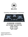
Operating and Installation Instructions
AS 920GR/R/MB - AS 930G/R/B
AS 9402B/BG/G/R - AS 9403B/G/R
GHG 732A NEW - GHG 733B/C NEW
AS 920 - AS 930
AS 920L - AS 930L
AS 9202 - AS 9203
DG 01 - DG 02
To avoid the risk of accidents or
damage to the appliance it is
essential to read these instructions
before it is installed and used for the
first time.
Contents
Contents
AS 920GR/R/MB
Description of the appliance............................................................................04
DG 02
AS 930G/R/B
Description of the appliance............................................................................06
Installation..................................................................................................................32
AS 9402B/BG/G/R
Description of the appliance............................................................................08
AS 9403B/G/R
Description of the appliance............................................................................10
GHG 732A NEW
Description of the appliance............................................................................12
GHG 733B/C NEW
Description of the appliance............................................................................14
Description of the appliance............................................................................30
Warning and Safety instructions................................................................................34
Before using for the first time.....................................................................................41
Using the appliance...................................................................................................42
Cleaning and care.....................................................................................................47
Problem solving guide...............................................................................................51
After sales service.....................................................................................................52
AS 920
Description of the appliance............................................................................16
AS 930
Description of the appliance............................................................................18
AS 920L
Description of the appliance............................................................................20
AS 930L
Description of the appliance............................................................................22
AS 9202
Description of the appliance............................................................................24
AS 9203
Description of the appliance............................................................................26
DG 01
2
Description of the appliance............................................................................28
3
Description of the appliance
Description of the appliance
Model
Burners
AS 920GR/R/MB
6
3
4
5
4
3
2
1
1
Controls
1
Left
2
Right
2
1
2
3
4
3
4
4
Burner
Pan support
5
6
Ignition electrode
Thermocouple
Burner body
Crown
External cap
Internal cap
5
Description of the appliance
Description of the appliance
Model
Burners
AS 930G/R/B
6
5
7
6
8
5
11
4
10
3
9
2
8
1
1
Controls
Left
2
Middle
3
Right
4
Timer (for right burner)
1
2
3
7
4
1
2
3
4
5
5
6
7
8
6
Large burner
Small burner
6
Ignition electrode
Burner body
Thermocouple
Crown
External cap
Internal cap
7
8
9
10
11
Burner body
Thermocouple
Ignition electrode
Crown
Cap
Small pan support
Large pan support
7
Description of the appliance
Description of the appliance
Model
Burners
AS 9402B/BG/G/R
6
4
5
5
4
3
2
1
Controls
1
Left
2
Right
3
Timer (for right burner)
4
5
Burner
Pan support
2
3
1
1
2
3
4
5
6
8
Ignition electrode
Thermocouple
Burner body
Crown
External cap
Internal cap
9
Description of the appliance
Description of the appliance
Model
Burners
AS 9403B/G/R
6
5
7
6
8
5
11
4
10
3
1
Controls
1
Left
2
Middle
3
Right
4
Timer (for right burner)
5
6
7
8
10
Large burner
Small burner
2
3
9
2
8
1
7
4
1
2
3
4
5
6
Ignition electrode
Thermocouple
Burner body
Crown
External cap
Internal cap
7
8
9
10
11
Burner body
Thermocouple
Ignition electrode
Crown
Cap
Small pan support
Large pan support
11
Description of the appliance
Description of the appliance
Model
Burners
GHG 732A New
6
3
4
5
4
3
2
1
1
Controls
1
Left
2
Right
3
4
Burner
Pan support
2
1
2
3
4
5
6
12
Ignition electrode
Burner body
Thermocouple
Crown
External cap
Internal cap
13
Description of the appliance
Description of the appliance
Model
Burners
GHG 733B/C New
6
4
7
5
8
6
5
11
16
4
10
15
3
9
2
1
1
2
2
4
5
6
7
8
14
13
7
12
3
1
Controls
1
Left
2
Middle
3
Right
14
8
3
4
5
6
Burner body
Ignition electrode
Thermocouple
Crown
External cap
Internal cap
7
8
9
10
11
Ignition electrode
Burner body
Thermocouple
Crown
Cap
12
13
14
15
16
Thermocouple
Burner body
Ignition electrode
Crown
Cap
Large burner
Small burner
Medium burner
Small pan support
Large pan support
15
Description of the appliance
Description of the appliance
Model
Burners
AS 920
3
5
4
6
12
5
11
4
10
3
9
2
8
1
1
Controls
1
Left
2
Right
3
4
5
16
Medium burner
Large burner
Pan support
7
2
1
2
3
4
5
6
Burner body
Thermocouple
Ignition electrode
Crown
External cap
Internal cap
7
8
9
10
11
12
Ignition electrode
Thermocouple
Burner body
Crown
External cap
Internal cap
17
Description of the appliance
Description of the appliance
Model
Burners
AS 930
4
7
5
8
6
17
5
16
6
11
15
10
4
9
3
14
8
2
13
7
12
1
1
Controls
1
Left
2
Middle
3
Right
2
3
1
2
3
4
5
4
5
6
7
8
18
Medium burner
Small burner
Large burner
6
Burner body
Thermocouple
Ignition electrode
Crown
External cap
Internal cap
7
8
9
10
11
Burner body
Ignition electrode
Thermocouple
Crown
Cap
12
13
14
15
16
17
Ignition electrode
Thermocouple
Burner body
Crown
External cap
Internal cap
Small pan support
Large pan support
19
Description of the appliance
Description of the appliance
Model
Burners
AS 920L
5
6
7
5
4
3
2
1
Controls
1
Left
2
Right
3
Timer (for right burner)
4
5
Burner
Pan support
2
3
1
1
2
3
4
5
6
20
Ignition electrode
Thermocouple
Burner body
Crown
External cap
Internal cap
21
Description of the appliance
Description of the appliance
Model
Burners
AS 930L
6
5
7
6
8
5
11
4
10
3
1
Controls
1
Left
2
Middle
3
Right
4
Timer (for right burner)
5
6
7
8
22
Large burner
Small burner
2
3
4
9
2
8
1
7
1
2
3
4
5
6
Ignition electrode
Thermocouple
Burner body
Crown
External cap
Internal cap
7
8
9
10
11
Burner body
Thermocouple
Ignition electrode
Crown
Cap
Small pan support
Large pan support
23
Description of the appliance
Description of the appliance
Model
Burners
AS 9202
6
5
3
4
5
12
11
4
10
3
9
8
2
7
1
1
Controls
1
Left
2
Right
3
4
5
24
Large burner
Medium burner
Pan support
2
1
2
3
4
5
6
Burner body
Ignition electrode
Thermocouple
Crown
External cap
Internal cap
7
8
9
10
11
12
Thermocouple
Ignition electrode
Burner body
Crown
External cap
Internal cap
25
Description of the appliance
Description of the appliance
Model
Burners
AS 9203
6
5
8
6
9
7
18
5
12
17
11
4
16
10
3
15
9
2
8
14
7
13
1
1
2
3
4
1
2
Controls
1
Left
2
Middle
3
Right
4
Timer (for right burner)
5
6
7
8
9
26
3
4
5
6
Burner body
Ignition electrode
Thermocouple
Crown
External cap
Internal cap
7
8
9
10
11
12
Thermocouple
Ignition electrode
Burner body
Crown
External cap
Internal cap
13
14
15
16
17
18
Burner body
Thermocouple
Ignition electrode
Crown
External cap
Internal cap
Medium burner
Small burner
Large burner
Small pan support
Large pan support
27
Description of the appliance
Model
Description of the appliance
Burners
DG 01
6
5
3
4
2
3
2
1
1
1
2
3
Control
Burner
Pan support
1
2
3
4
5
6
28
Burner body
Thermocouple
Ignition electrode
Crown
External cap
Internal cap
29
Description of the appliance
Description of the appliance
Model
Burners
DG 02
6
6
5
11
4
10
4
5
9
3
3
8
2
7
1
1
Controls
1
Front
2
Back
3
4
5
6
30
Small burner
Large burner
2
1
2
3
4
5
6
Burner body
Thermocouple
Ignition electrode
Crown
External cap
Internal cap
7
8
9
10
11
Burner body
Ignition electrode
Thermocouple
Crown
Cap
Small pan support
Large pan support
31
Installation
Installation
Cut-out
Important
Make the countertop cut-out following the dimensions given in the illustration.
This appliance should be installed with plenty of space on either side.
850
Gas connection
490
Connection to the gas supply, or conversion from one type of gas to another should only
be undertaken by an approved and registered gas installer in strict accordance with
local and national safety and building regulations. Every appliance should have its own
isolating valve and test point.
790
440
Check with your local gas supplier about the type of gas and its calorific value, and
compare this information with the type of gas quoted on the hob data plate.
The installer is responsible for ensuring that the appliance functions correctly when
installed.
The gas installation must be made in such a way that the isolating valve is visible and
easily accessible after the appliance has been built in.
A test for possible leakages must be carried out after installation.
32
Model
Cut-out dimension
AS 920GR/R/MB
665 * 385 mm
AS 930G/R/B
745 * 415 mm
AS 9402B/BG/G/R - AS9403B/G/R
790 * 440 mm
GHG 732A NEW - GHG 733B/C NEW
660 * 360 mm
AS 920
660 * 360 mm
AS 930
665 * 385mm
AS 920L - AS 930L
790 * 440 mm
AS 9202
660 * 360mm
AS 9203
680 * 380 mm
DG 01 - DG 02
280 * 460mm
Safety regulations demand that a pressure test nipple is installed near a gas hob to allow an engineer to test the pressure following servicing.
33
Warning and Safety instructions
Gas-heated appliance
Safety precautions to take if you smell gas
- Turn off the gas emergency control valve immediately.
This is usually located near the gas meter.
- Eliminate all sources of ignition in a safe manner.
Do not smoke, light cigarette lighters or matches.
Warning and Safety instructions
To avoid the risk of accidents and damage to the appliance, please read these instructions carefully before using it for the first time. They contain important notes on its installation, safety, use and maintenance.
The use of the appliance by the elderly or infirm or those who have not used the appliance before should be supervised by a competent and responsible person to avoid the
risk of injury.
- Do not operate electrical lights or switches, i.e. do not switch them “On” or “Off”.
Keep these instructions in a safe place for reference, and pass them on to any future
user.
- Open all doors and windows to ventilate the area.
Installation and connection
- If the smell of gas persists, evacuate the building.
The connection to the gas supply must be carried out by a suitably qualified and competent person in strict accordance with current local and national safety regulations.
Malloca cannot be held liable for damage caused by incorrect installation or connection.
Ensure that the gas pipe is installed in such a way that it does not touch any parts of the
appliance which become hot. This could cause damage.
34
35
Warning and Safety instructions
Warning and Safety instructions
Correct usage
Safety with children
For safety reasons this appliance must only be operated after it has been built in. This is
necessary to ensure that all electrical components are shielded.
The appliance is only intended for use by adults who have read these Operating instructions.
This appliance is intended for domestic use only and is not to be used for commercial
purposes.
This appliance is not a toy! To avoid the risk of injury, keep children well away, and do
not allow them to play with it or use the controls. They will not understand the potential dangers posed by it. They should be supervised whenever you are working in the
kitchen.
Use this appliance for the preparation of food only. Any other usage is at the owner’s
risk and could be dangerous. Malloca cannot be held liable for damage resulting from
incorrect or improper use or operation.
Do not use the appliance to heat up the room. Due to the high temperatures radiated,
objects near the appliance could catch fire. The life of the appliance could also be reduced.
Using the appliance will cause a build-up of heat and moisture in the room in which it is
installed. Ensure that the room has sufficient natural or mechanical means of ventilation,
e.g. an cooker hood.
If the appliance is used for very long periods of time, additional ventilation of the room
may be necessary, e.g. by opening windows or doors, or running the cooker hood on
the highest setting.
This appliance must not be set up or operated in the open air.
Make sure all the components of the gas burner have been correctly assembled before
switching on.
When using the appliance, ensure that any burners in use are always covered with a
pan. If using a cooker hood above it flames could be drawn up by the suction of the
cooker hood, parts of which could then be damaged or even set on fire.
Older children may use the appliance only when its operation has been clearly explained to them and they are able to use it safely, recognizing the dangers of misuse.
The appliance gets hot when in use and remains hot for quite a while after being
switched off. To safeguard against burning, keep children well away from the appliance
at all times.
Do not store anything which might arouse a child’s interest in storage
areas above or next to the appliance. Otherwise they could be tempted into climbing
onto the appliance with the risk of burning themselves.
Keep all pans out of reach of children. Turn pan handles inwards away from the edge of
the hob. Danger of burning or scalding.
Packaging, e.g. cling film, polystyrene and plastic wrappings,must be kept out of the
reach of babies and young children. Danger of suffocation. Dispose of or recycle all
packaging safely as soon as possible.
Before disposing of an old appliance, disconnect it from the gas supplies. Cut off and
render any plug useless. Cut off the cable directly behind the appliance to prevent misuse. This should be done by a competent person.
Pans must be the correct size for the burner they are used on (see “Suitable pans”).
A pan which is too small will be unstable on the pan support. If the pan diameter is too
large flames can spread out to the sides and damage or burn the worktop, wall claddings or surrounding units and also parts of the hob. Malloca cannot be held liable for
this type of damage.
Do not store any inflammable objects near the appliance.
36
37
Warning and Safety instructions
Warning and Safety instructions
Protecting the appliance from damage
Protection from burning
Unless the pan manufacturer states that you can do so, do not use pans with very thin
bases on this hob, and never heat up empty pans as they could get damaged. This
could also damage the appliance.
The appliance gets hot when in use, and remains hot for quite a while after being
switched off. Do not touch it whilst it could still be hot.
There are areas which may be subject to infestation by cockroaches or other vermin,
pay particular attention to keeping the appliance and its surroundings in a clean condition at all times. Any damage which may be caused by cockroaches or other vermin will
not be covered by the appliance guarantee.
For added protection, it is advisable to use heat-resistant pot holders or oven gloves
when using the appliance. Ensure that they do not come into contact with the flames.
Do not use large cloths, tea towels or similar as the ends could touch the flames and
catch fire. Take care not to let the gloves get damp or wet, as this causes heat to transfer through the material more quickly with the risk of burning yourself.
Do not heat up unopened tins of food on the hob. Presssure can build up and they may
explode, resulting in injury and scalding or damage.
Do not use the appliance as a resting place for anything else. The article could melt or
catch fire if residual heat is still present or if the appliance is switched on by mistake.
Do not cover the appliance, e.g. with a cloth, kitchen foil, etc. This could be a fire hazard
if the appliance is switched on by mistake.
Remove splashes of fat and other food debris from the surface as soon as possible.
These are a fire hazard.
Never leave the appliance unattended when cooking with oil or fat. Very hot oil can
catch fire and could even set a cooker hood above on fire. Always heat fat slowly,
watching as it heats.
If, despite this, oil or fat does catch fire, do not attempt to put out the flames with water.
Use a suitable fire blanket, saucepan lid, damp towel or similar to smother the flames.
Do not flambé under a cooker hood. The flames could set the cooker hood on fire.
Ensure that the flames from the burner do not spread out beyond the base and up the
sides of the pan.
38
39
Warning and Safety instructions
Before using for the first time
Appliance faults
Cleaning and heating up for the first time
In the event of damage or a defect, switch off the appliance immediately. Turn off the
gas supply tap. It should not be used again until it has been repaired.
Do not reconnect the appliance to the main gas supply until after it has been repaired.
Before using for the first time clean the hob and all removable parts as follows:
Repairs to the gas components of this appliance must only be carried out by a suitably
qualified person. Repairs and other work by unqualified persons could be very dangerous and could damage the appliance. Malloca cannot be held liable for unauthorised
work. Never open the housing of the appliance.
- The removable parts of the gas burner assembly can be washed in a mild solution of
water and washing-up liquid. Wipe dry and reassemble in the correct order (see “Cleaning and care”).
- Clean the stainless steel surface with a damp cloth only, and then wipe dry.
While the appliance is under guarantee, repairs should only be undertaken by a service
engineer authorised by Malloca. Otherwise the guarantee is invalidated.
Metal components have a protective coating which may give off a slight smell when
heated up for the first time. The smell and any vapours will dissipate after a short time
and do not indicate a faulty connection or appliance.
Further safety notes
Disposal of packing material
When using an electric socket near the appliance, care should be taken that the cable
of the electrical appliance does not come into contact with the hot appliance. The insulation on the cable could become damaged, giving rise to an electric shock hazard.
The transport and protective packing has been selected from materials which are environmentally friendly for disposal and can normally be recycled.
Do not use plastic or aluminium foil containers.These melt at high temperatures and
could catch fire.
Packaging, e.g. cling film, polystyrene and plastic wrappings, must be kept out of the
reach of babies and young children. Danger of suffocation. Dispose of or recycle all
packaging materials safely as soon as possible.
Spray canisters, aerosols and other inflammable substances must not be stored in a
drawer under the hob. Cutlery inserts must be heat-resistant.
If the appliance has not been used for a longer period of time it should be thoroughly
cleaned before it is used again. It is also advisable to have the appliance tested for
safety. This should be done at regular intervals.
Malloca cannot be held liable for damage caused by non-compliance with these Warning and Safety instructions.
40
41
Using the appliance
Using the appliance
Switching on, adjusting the flame and switching off
To adjust the flame:
The control is used to switch on the burner and regulate the strength of the flame.
Once the flame is burning well (after letting the control go), select a setting between the
twin and single flame symbols. The flame will become weaker when the control is turned
anti-clockwise and stronger when it is turned clockwise. It is not necessary to press in
the control when adjusting the setting.
Control the flame so that it does not spread out beyond the sides of the pan. As the
outer part of the flame is much hotter than the centre, the tips of the flames should stay
beneath the pan base. Flame tips which extend beyond the sides of the pan merely
warm up the air in the room and can also damage pan handles and increase the danger
of injury.
The gas supply is turned off
strong flame
weak flame
The burners can only be switched on by pressing in the appropriate control and turning
it anti-clockwise, and switched off by turning the control clockwise.
- Trying to switch on a burner without pressing in the control,
- Switching on a burner by turning it clockwise, or
- Switching off a burner by turning it anti-clockwise, can damage components in the appliance. Malloca cannot be held liable for this type of damage.
To swtich off
Turn the control clockwise to position “
“.
This stops the flow of gas and the flame goes out.
To switch on:
The control for the burner required must be pressed in and turned anti-clockwise to the
twin flame symbol to switch on.
When the flame ignites, keep the control pressed in for 8-10 seconds, and then let it go.
If the flame goes out, repeat the procedure, keeping the control pressed in for a few
extra seconds.
42
43
Using the appliance
Using the appliance
Suitable pans
You should select pans which are suitable for the burner they are to be used on. In
general: use larger diameter pans on the large burner and smaller diameter pans on the
small burner.
Model
Burner
Power(kw)
Min. pan base
diameter (cm)
Max. pan base
diameter (cm)
9402B/BG/G/R
920L
732A New
Large
3.8 * 2
14
26
9403B/G/R
930L
Large
Small
3.8 * 2
1.0 * 1
14
10
26
20
920R/GR/MB
Wok
4.5 * 2
14
30
930R/G/B
Wok
Small
4.5 * 2
1.0 * 2
14
10
30
20
Large
Medium
Small
3.8 * 1
3.0 * 1
1.0 * 1
14
14
10
26
24
20
920
Large
Medium
3.8 * 1
2.5 * 1
14
14
26
24
930
Large
Medium
Small
3.8 * 1
2.5 * 1
1.5 * 1
14
14
12
26
24
22
9202
Large
Medium
3.4 * 1
2.4 * 1
14
14
26
24
9203
Large
Medium
Small
3.4 * 1
2.4 * 1
1.4 * 1
14
14
12
26
24
22
DG 01
Large
3.8 * 1
14
26
DG 02
Medium
Small
2.5 * 1
1.5 * 1
14
14
24
22
733B/C New
44
Wide, shallow pans are preferable to tall, narrow ones. They will heat up faster.
Pans with thick bases are preferable as these distribute heat more evenly, and therefore
lessen the risk of heat spots occurring which can cause food to stick or burn. With thin
bases heat is conducted quickly to the food, however there is a danger of food heating
up unevenly and too quickly increasing the risk of burning. Stir the food frequently.
Any heat-resistant pans can be used on a gas burner.
Remember when purchasing new pans that manufacturers usually refer to the diameter
at the top of the pan in their documentation.
Refer to the chart above and ensure that the pan diameter falls within the minimum and
maximum diameters given for the burner you are using. A pan which is too small will be
unstable on the pan support. If the pan diameter is too large flames can spread out to
the sides and damage or burn the worktop, wall claddings or surrounding units and also
parts of the hob. The manufacturer cannot be held liable for this type of damage.
Use a pan lid whenever possible to minimise heat loss.
45
Using the appliance
Cleaning and care
Safety cut-out
General notes
This appliance is fitted with a thermoelectric ignition safety device which cuts off the
supply of gas to a burner if the flame goes out, for example if food has boiled over, or if
there was a sudden draught.
Clean the appliance regularly, preferably after each use. Allow the appliance to cool
down to a safe temperature before cleaning.
To use the burner again, turn the control clockwise to the “
normal.
” position and switch on as
The safety cut-out operates independently from the battery supply. This means that it
will still work if the battey run out.
Using your hob during a battery run out
If there is an interruption to the battery supply the gas can be ignited with a match:
- Press in the relevant control and turn it anti-clockwise to the large flame symbol.
Do not use any sharp pointed objects which could damage the seal between the glass
surface and the worktop.
Do not let the ignitor in the burner get wet. If it gets wet it will not spark.
After cleaning, dry the surfaces thoroughly with a soft cloth to prevent a build-up of
limescale deposits.
Pan supports, controls
Remove the pan supports.
- Hold the control pressed in and light the gas at the burner with a match.
The pan supports and the controls can be cleaned with a solution of warm water and a
little washing up liquid applied with a soft sponge. Soak stubborn soiling first to loosen it.
- Keep the control pressed in for a further 8-10 seconds and then release it.
Finally, wipe dry using a soft cloth.
46
47
Cleaning and care
Cleaning and care
Glass surfaces
Spillages etc. should be cleaned off as soon as possible.
6
Most soiling can be wiped off using a damp cloth. Stubborn soiling may need to be
removed with a shielded scraper blade.
5
6
5
To remove any limescale deposits, caused for example by water boiling over and metallic marks (aluminium deposits) apply a few drops of a proprietary cleaning agent for
glass surfaces using a soft cloth or kitchen paper towel.
Note that some cleaning agents contain a protective additive designed to prevent water
marks and smears adhering to the surface.
After cleaning wipe the hob surface with a damp cloth and then dry it with a clean soft
cloth.
Burners
4
4
3
3
2
2
1
1
The burners can be dismantled for cleaning once they have cooled down.
Proceed as follows:
- Take off all the removable parts of the burner and wash in a solution of hot water and
washing-up liquid. Then dry them all thoroughly. Make sure that the flame slits are clean
and completely dry.
Re-assemble the burner as follows:
The surface of the burner cap will gradually become more matt with time. This is quite
normal and will not affect the operation of the hob.
- Place the crown 4 onto the burner body 1 so that the thermocouple 3 and the ignition electrode 2 extend through their respective holes in the crown. The crown must
click into place correctly.
- Wipe the fixed parts of the burner base with a damp cloth and dry afterwards.
- Place the external cap
- Gently wipe the ignitor and the ignition safety device with a clean cloth.
Important: replace parts in the correct order after cleaning.
48
5
and internal cap
6
in position.
49
Cleaning and care
5
Problem solving guide
Repairs to the gas components of this appliance must only be carried out by a suitably
qualified and competent person in strict accordance with current local and national
safety regulations to ensure safety. Repairs and other work by unqualified persons
could be dangerous. Malloca cannot be held liable for unauthorized work.
What to do if ... the burner does not ignite after several attempts
Check whether
4
- The burner is correctly assembled.
- The gas supply tap is turned on.
3
2
1
- The burner is dry and clean.
- The flame slits are dry and unblocked.
... the gas flame goes out after being lit
Check whether the burner cap is correctly positioned.
... the ignitor on the burner does not spark
Re-assemble the burner as follows:
- Place the crown 4 onto the burner body 1 so that the thermocouple 3 and the ignition electrode 2 extend through their respective holes in the crown. The burner head
must click into place correctly.
- Place the cap
5
flat over the crown . When correctly positioned it will not slide about.
Check whether food deposits have lodged themselves between the ignitor and the
burner cap.
Carefully remove any soiling. Do not let the ignitor get wet.
... the flame suddenly looks different
Check whether the burner is correctly assembled.
Important: replace parts in the correct order after cleaning.
50
51
After sales service
In the event of any faults which you cannot remedy yourself, or if the appliance is under
guarantee, please contact:
– Malloca dealer, or
EXCLUSIVE DISTRIBUTOR IN VIETNAM
BACH HOP KITCHEN APPLIANCES CO., LTD
– Malloca Technical Service Department (see back cover for address).
When contacting Malloca Technical Service Department, please quote the model and
serial number of your appliance swhich are given on the data plate.
52
Office and Showroom:
279 Nguyen Van Troi St., Ward 10, Phu Nhuan Dist., HCM City
Tel: (84) 8 39975 893 - (84) 8 39975 894
Fax: (84) 8 39970 135
Email: [email protected]