1
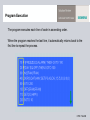
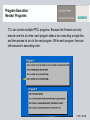
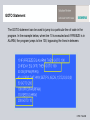
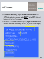
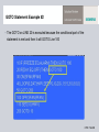
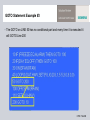
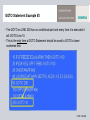
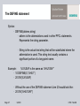
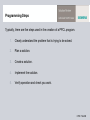
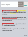
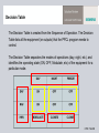
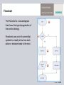
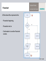
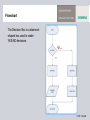
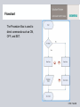
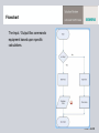
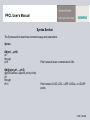
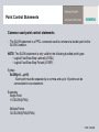
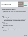
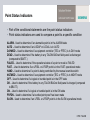
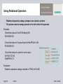
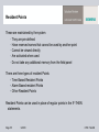
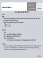
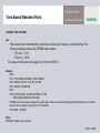
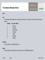
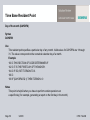
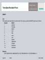
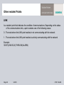
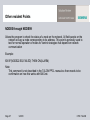
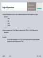
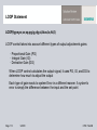
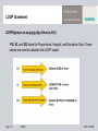
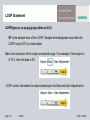
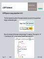
Introduction to Powers Process Control Language (PPCL) Protection notice / Copyright notice Items to be Covered 1. POINTS 2. PPCL OVERVIEW 3. CONDITIONAL CONTROL 4. POINT CONTROL 5. PROGRAM CONTROL Page 2 9/2010 CPS / TALON Basic Points LDI---Logical Digital Input LDO---Logical Digital Output LAI---Logical Analog Input LAO---Logical Analog Output CPS / TALON Bundled Points Bundled points combine two or more digital input and output points to control devices requiring more than one signal. L2SL---Logical 2-state Latched L2SP---Logical 2-state Pulsed LFSSL---Logical Fast-Slow-Stop Latched LOOAL---Logical On-Off-Auto Latched LOOAP---Logical On-Off-Auto Pulsed CPS / TALON Virtual Points Virtual points are points defined in the field panel that do not represent a physical device. A room temperature set point is an example of a virtual point. LDO---Logical Digital Output LAO---Logical Analog Output Note: Input points can also be commanded, and therefore used as a virtual point, but this is not recommended since LAI points have no initial value. CPS / TALON Point Names Point names can use up to 30 characters Can use non-alphanumeric characters such as decimal points, ampersands, and dashes. (.*&%-$ etc… Can more easily be segmented to show various components of the point name. Example: Point name with three segments B304. AHU04.SAT CPS / TALON Programming Objectives Definition of PPCL and its function Steps to create PPCL programs How to use the PPCL User’s Manual Rules and Guidelines for PPCL CPS / TALON What is PPCL? Advanced Tool: PPCL is an advanced tool that works with the features of the Siemens TALON BACnet building automation system Where is PPCL Used: • TC Modular Controller • TC Compact Controllers • Reduced set in the Programmable TECs (PTEC) PPCL consists of statements that are used to monitor and control system components. CPS / TALON PPCL Sample Program The listing below shows part of a PPCL program. This program controls a supply fan, return fan and a virtual point that is used to control the supply air temperature. The PPCL program consists of a series of numbered lines that contain command statements. The common statements act on points to monitor and control the system components. Line 30 and 100 are examples of a Command statement, which is used to convey instructions for the field panel to execute. Every line of PPCL starts with a line number CPS / TALON Program Execution The program executes each line of code in ascending order. When the program reaches the last line, it automatically returns back to the first line to repeat the process. CPS / TALON Program Execution Nested Programs TC’s can contain multiple PPCL programs. Because the firmware can only execute one line at a time, each program takes a turn executing a single line, and then passes its turn to the next program. Within each program, lines are still executed in ascending order. CPS / TALON GOTO Statement The GOTO statement can be used to jump to a particular line of code in the program. In the example below, when line 10 is executed and if FREEZE is in ALARM, the program jumps to line 100, bypassing the lines in-between. CPS / TALON GOTO Statement GOTO statements MUST always jump to a HIGHER line number. NEVER use a GOTO statement to jump to a lower number EXCEPT for the GOTO statement located on the last line of the program. Do not use a GOTO to transfer control to the top of a program before the last line is executed – time based commands (LOOP, WAIT, etc.) will not function properly. CPS / TALON GOTO Statement Example #1 The GOTO on LINE 10 is executed because the conditional part of the statement is met and then will GOTO Line 100 CPS / TALON GOTO Statement Example #2 The GOTO on LINE 20 is executed because the conditional part of the statement is met and then it will GOTO Line 100 CPS / TALON GOTO Statement Example #3 The GOTO on LINE 50 has no conditional part and every time it is executed it will GOTO Line 200 CPS / TALON GOTO Statement Example #3 The GOTO on LINE 200 has no conditional part and every time it is executed it will GOTO Line 10. This is the only time a GOTO Statement should be used to GOTO a lower numbered line. CPS / TALON The DEFINE statement • Creates abbreviated notation for long point names • When used in a program a percentage (%) must be placed before and after the abbreviation. • This statement allows a program logic to be easily duplicated from panel to panel provided structured point names. Page 26 9/2010 CPS / TALON The DEFINE statement Syntax: • DEFINE(abbrev,string) • abbrev is the abbreviations used in other PPCL statements. Represents the string parameter. • String is the actual text string that will be substituted where the abbreviation is used. This string text usually contains a significant portion of a long point name. Example: %X%SAF is the same as “AHU1SAF” • 10 DEFINE(X,”AHU1”) • 20 ON(%X%SAF) • Without the use of the DEFINE statement Line 20 would look like: • 20 ON(“AHU1SAF”) Page 27 9/2010 CPS / TALON Creating PPCL Programs There are many ways to create a PPCL program. This section provides an overview of the steps and tools used to create effective PPCL programs. CPS / TALON Programming Steps Typically, there are five steps used in the creation of a PPCL program. 1. Clearly understand the problem that is trying to be solved. 2. Plan a solution. 3. Create a solution. 4. Implement the solution. 5. Verify operation and check you work. CPS / TALON PPCL Program Development PPCL program development uses several steps to develop and test the program. These are listed below. Each step in the process builds on the result from the previous step. 1. Sequence of Operation 2. Decision Table 3. Flowchart 4. PPCL Code CPS / TALON Sequence of Operation The first step in creating a PPCL program is to analyze the problem. During the analysis, a Sequence of Operation is developed and/or reviewed. The Sequence of Operation describes how the system should operate. Once the PPCL program is created, its operation must be tested and compared to the Sequence of Operation. CPS / TALON Sequence of Operation Between the scheduled hours of occupancy, the supply and return air fans will constantly run, and the hot water valve will modulate to maintain supply air temperature. Outside of the scheduled hours of occupancy, the supply and return fans will be off, and the hot water valve will be shut and a low temperature detector will be provided in the supply duct. If the low temperature detector trips, the supply and return fans will be shut off, and the hot water valve will be closed. Note: Notice that the modes are separated and the equipment that it controls is defined during those modes. CPS / TALON Decision Table The Decision Table is created from the Sequence of Operation. The Decision Table lists all the equipment (or outputs) that the PPCL program needs to control. The Decision Table separates the modes of operations (day, night, etc.) and identifies the operating state (ON, OFF, Modulate, etc) of the equipment for a particular mode. CPS / TALON Flowchart The Flowchart is a visual diagram that shows the logical progression of the control strategy. Flowcharts use a set of conventitial symbols to visually show how each action or decision leads to the next. CPS / TALON Flowchart A Directional Box represents the: Flowchart beginning, Flowchart end or Continuation to another flowchart section. CPS / TALON Flowchart The Decision Box is a diamondshaped box used to make YES/NO decisions. CPS / TALON Flowchart The Procedure Box is used to direct commands such as ON, OFF, and SET. CPS / TALON Flowchart The Input / Output Box commands equipment based upon specific calculations. CPS / TALON PPCL Program Development The final step is to enter the PPCL code. Since the Decision Table and Flowchart have already been developed, the PPCL code can be written more easily. Always test your program by comparing its functionality with the Flowchart, Decision Table, and the Sequence of Operation. CPS / TALON PPCL User’s Manual Syntax Section The Syntax section describes command usage and parameters: Syntax ON(pt1,...,pt16) pt1 through pt16 ON(@prior,pt1,...,pt15) @prior Defines a specific point priority. pt1 through Pt15 Point names that are commanded to ON. Point names of LDO, L2SL, L2SP, LOOAL, or LOOAP points CPS / TALON PPCL User’s Manual Use Section The Use section describes what function the command performs and provides on-line examples of program code. Use Changes the operational status of an ON/OFF/AUTO point to ON. • A maximum of 16 points can be changed with one ON command. • A maximum of 15 points can be defined with one ON(@prior…) command. Example 100 IF (OATEMP.LT.60.0)THEN ON(@NONE, PUMP1,PUMP2) CPS / TALON PPCL User’s Manual Remarks and See Also Section Remarks Give helpful hints regarding the command. See Also Refers you to other similar types of commands See also AUTO, FAST, OFF, SLOW CPS / TALON Point Control Statements Common used point control statements • The ON statement is a PPCL command used to command a digital point to the ON Condition. Syntax: ON(pt1,...,pt16) Each point must be separated by a comma and up to 16 points can be commanded in one statement. Examples Single Point 10 ON(SFAN) Multiple Points 20 ON(SFAN,RFAN) 30 ON(FAN1,FAN2,FAN3,FAN4,FAN5) CPS / TALON Point Control Statements Common used point control statements • The OFF statement is a PPCL command used to command a digital point to the OFF Condition. Syntax: OFF(pt1,...,pt16) Each point must be separated by a comma and up to 16 points can be commanded in one statement. Examples Single Point 10 OFF(SFAN) Multiple Points 20 OFF(SFAN,RFAN) 30 OFF(FAN1,FAN2,FAN3,FAN4,FAN5) CPS / TALON Point Control Statements Common used point control statements • The SLOW statement is a PPCL command used to command a bundle point to the SLOW Condition. NOTE: The SLOW statement is only valid for the following bundled point types: Logical Fast-Slow-Stop Latched (LFSSL) Logical Fast-Slow-Stop Pulsed (LFSSP) Syntax: SLOW(pt1,...,pt16) Each point must be separate by a comma and up to 16 points can be commanded in one statement. Examples Single Point 110 SLOW(SFAN) Multiple Points 120 SLOW(SFAN,RFAN) CPS / TALON Point Control Statements Common used point control statements • The FAST statement is a PPCL command used to command a bundled point to the FAST Condition. NOTE: The FAST statement is only valid for the following bundled point types: Logical Fast-Slow-Stop Latched (LFSSL) Logical Fast-Slow-Stop Pulsed (LFSSP) Syntax: FAST(pt1,...,pt16) Each point must be separate by a comma and up to 16 points can be commanded in one statement. Examples Single Point 110 FAST(SFAN) Multiple Points 120 FAST(SFAN,RFAN) CPS / TALON Point Control Statements Common used point control statements • The SET statement is a PPCL command used to command an assign value to an analog point. Syntax: SET(value, pt1,...,pt16) First part of the statement is the value you want each point to be. Each point must be separated by a comma and up to 16 points can be commanded in one statement. Examples 540 SET(10,ETHR1) 550 SET(3,CNDVLV,HWVLV,DAMPER) Note: Also an assignment (=) can be used to set a point to a single value 560 ETHR2 = 5 CPS / TALON Conditional Statements The IF-THEN statement is used to test for a specific condition The condition being tested for is the expression. If TRUE, then the command after the THEN is executed. If FALSE, the program does not execute and continues to the next line Expressions are used to compare point values: • For example compare the value of the Hot Water Pump (HWPMP) to On or compare the Outside Air Temperature (OAT) to 72 degrees. Expressions are either relational or logical. Command section is placed after the THEN and is only executed if the expression evaluated is TRUE. CPS / TALON Conditional Statements The IF-THEN statement Example The expression testing for the point FAN to be ON. If the FAN is ON, then the expression is TRUE and the command is executed. If the FAN is OFF, then the expression is FALSE and the Command is ignored. The statement would be written as: 110 IF(FAN.EQ.ON) THEN ON(PUMP) CPS / TALON Point Status Indicators Part of the conditional statements are the point status indicators Point status indicators are used to compare a point to a specific condition ALARM - Used to determine if an alarmable point is in the ALARM state AUTO – Used to determine if an LOOAP or LOOAL is in AUTO DAYMOD – Used to determine if a equipment controller (TEC or PTEC) is in DAY mode DEAD – Used to determine if the battery in any TALON BACnet field panel is discharged (compared to $BATT.) FAILED – Used to determine if the operational state of a point or node is FAILED FAST – Used to determine if an LFSSL or LFSSP point is in the FAST operational mode HAND – Used to determine if a point is being controlled by the manual override switch NGTMOD – Used to determine if a equipment controller (TEC or PTEC) is in NIGHT mode OFF – Used to determine if a logical or bundled point is in the OFF state OK – Used to determine if the battery in any TALON BACnet field panel is charged (compared to $BATT.) ON – Used to determine if a logical or bundled point is in the ON state PRFON – Used to determine if a bundled point proof has been made SLOW – Used to determine if an LFSSL or LFSSP point is in the SLOW operational mode CPS / TALON Relational Operators Part of the conditional statements is the relational operator Relational operators establish how factors of the conditional statements are compared .EQ. the relational operator Equal to is used to check if the first value is equal to the second value. Examples: FAN.EQ.ON (fan equals on) TEMP.EQ.72.0 (temperature equals 72) .GT. the relational operator Greater Than is used to check if the first value is greater than the second value. Examples: TIME.GT.08:00 (time greater than 8 am) TEMP.GT.72.0 (temperature greater than 72) .GE. the relational operator Greater Than or Equal To is used to check if the first value is greater than or equal to the second value. Example: TEMP.GE.72.0 (temperature greater than or equal to 72) Page 51 9/2010 CPS / TALON Relational Operators .LT. the relational operator Less Than is used to check if the first value is less than the second value. Examples: TIME.LT.17:00 (time less than 5 pm) TEMP.LT.72.0 (temperature less than 72) .LE. the relational operator Less Than or Equal To is used to check if the first value is less than or equal to the second value. Examples: TEMP.LE.72.0 (temperature less than or equal to 72) .NE. the relational operator Not Equal To is used to check if the first value is different than second value. Example: FAN.NE.ALARM (fan is not in alarm) PUMP.NE.FAILED (pump has not failed) Page 52 9/2010 CPS / TALON Using Relational Operators Relational operators always compare one value to another The points name is always placed on the left side of the operator Example: Check the status of the SFAN being ON SFAN.EQ.ON Check the status of the proof point of the RFAN to ON RFAN.NE.ON Check the status of a point to some value. AH1SAT.GT.85 DAMPER.LT.3 Evaluation Relations operators always evaluate to TRUE or FALSE. Page 53 9/2010 CPS / TALON Relational Operators IF-THEN Evaluation 1 The following relational expression is used in an IF-THEN statement. Example: IF(SFAN.NE.ON) THEN ON(SFAN) (If the SFAN is not ON then turn on the SFAN) The first step to evaluating an IF-THEN statement is examine the expression. The expression in the above statement is SFAN.NE.ON if it is TRUE then the command after the THEN is executed. If the expression is FALSE then the command after the THEN is ignored. Page 54 9/2010 CPS / TALON Resident Points These are maintained by the system • They are pre-defined • Have reserved names that cannot be used by another point • Cannot be viewed directly • Are activated when used • Do not take any additional memory from the field panel There are three types of resident Points Time Based Resident Points Alarm Based resident Points Other Resident Points Resident Points can be used in place of regular points in the IF-THEN statements. Page 55 9/2010 CPS / TALON Resident Points Time Base Resident Points Time Use This resident point maintains the current time and stores the value in military time. The TIME value can contain a value from 0:00 to 23:59. The following examples show how TIME stores values: 7:15 a.m. = 7:15 7:30 p.m. = 19:30 Example 500 C 501 C THIS CODE DEFINES A TIME PERIOD 502 C FROM 6:45 A.M. TO 5:30 P.M. FOR 503 C SFAN TO OPERATE. 510 IF(TIME.GE.6:45.AND.TIME.LE.17:30)THEN ON(SFAN) ELSE OFF(SFAN) Notes The time is updated every second. TIME cannot be used to assign a value to a virtual point since its value is not in a standard decimal form. CRTIME should be used for this purpose. TIME can be used in PPCL for comparison in the IF/THEN/ELSE statement. CPS / TALON Time Based Resident Point CURRENT TIME (CRTIME) Use This resident point maintains the current time and stores the value in a decimal format. The following examples show how CRTIME stores values: 7:15 a.m. = 7.25 7:30 p.m. = 19.50 The values for this point can range from 0.00 to 23.999721. Example 500 C 501 C THIS CODE DEFINES A TIME PERIOD 502 C FROM 6:45 A.M. TO 5:30 P.M. FOR 503 C SFAN TO OPERATE. 504 C 510 IF (CRTIME.GE.6.75.AND.CRTIME.LE.17.50) THEN ON(SFAN)ELSE OFF(SFAN) CRTIME can also be used to assign the current value of time to a virtual LAO type point which allows you to read the current time on a graphic, point log, etc. For example: 100 VTIME = CRTIME Notes CRTIME is updated every second. CPS / TALON Time Based Resident Point DAY Use This resident point specifies the current day of the week. The values used for the DAY point are as follows: Number Day of the Week 1 Monday 2 Tuesday 3 Wednesday 4 Thursday 5 Friday 6 Saturday 7 Sunday Example 300 IF (DAY.EQ.1) THEN TOTRAN = 0 Notes These values are not related to the modes used in the TODMOD statement. Page 58 9/2010 CPS / TALON Time Base Resident Point Day of the month (DAYOFM) Syntax DAYOFM Use This resident point specifies a particular day of any month. Valid values for DAYOFM are 1 through 31. The value corresponds to the numerical calendar day of a month. Example 160 C THIS SECTION OF CODE DETERMINES IF 162 C IT IS THE FIRST DAY OF THE MONTH. 164 C IF SO, SET TOTMON TO 0. 166 C 180 IF (DAYOFM.EQ.1) THEN TOTMON = 0 Notes This point is helpful when you have to perform certain operations on a specific day (for example, generating a report on the first day in the month). Page 59 9/2010 CPS / TALON Time Base Resident Point MONTH Use This resident point specifies the current month. The values used for the MONTH point are as follows: Number Month 1 January 2 February 3 March 4 April 5 May 6 June 7 July 8 August 9 September 10 October 11 November 12 December Example 950 IF (MONTH.GE.4.AND.MONTH.LE.10) THEN SEASON = 1 ELSE SEASON = 0 Page 60 9/2010 CPS / TALON Time Base Resident Point Seconds counter (SECNDS) SECNDS Use This resident point counts real time seconds and can be used as a timer. The computer adds one (1) to the SECNDS variable for every one second of real time that passes. • The initial value of the SECNDS point is set by a PPCL command. • The SECNDS point can be set to a maximum value of 9,999. Example 890 IF (SFAN.NE.PRFON) THEN SECNDS = 0 Notes For TALON field panels, each program has a unique SECNDS point. This point can also be viewed in the interface using the program name, system delimiter (:)SECNDS format. Page 61 9/2010 CPS / TALON Time Base Resident Point Seconds counters (SECND1 through SECND7) Syntax SECNDn n The number that describes which SECNDn point is referenced. Valid values for SECNDn are 1 through 7. Use These seven resident points count real time seconds and can be used as timers. The computer adds one (1) to the SECNDn variable for every one second of real time that passes. • The value of a SECNDn point can only be set by a PPCL command. • The maximum value a SECNDn point can be set to is 9,999. Example 600 IF(SECND1.GT.15) THEN ON(RF) ELSE OFF(RF) Notes For TALON field panels, each program has unique SECNSn points. These points can also be viewed in the interface using the program name, system delimiter (:)SECNDn format. Page 62 9/2010 CPS / TALON Other resident Points • $BATT • $PDL • LINK • NODE0 through NODE99 Page 63 9/2010 CPS / TALON Other resident Points $BATT TALON filed panels have the ability to monitor the strength of their backup battery, the $BATT resident point allows you to access that status. The status of $BATT can be tested for a numeric value. The status can also be tested by using the backup battery status indicators • $BATT numeric values are 0, 50, or 100 • A $BATT value of 0 indicates battery has discharged and must be replaced. • A $BATT value of 50 indicates battery is about to be discharged and should be replaced to prevent loss of data. • A $BATT value of 100 indicates battery does not need to be replaced. • $BATT status indicators are LOW, DEAD, or OK • A $BATT status is LOW or DEAD , then the battery has discharged and must be replaced. • A $BATT status of OK indicates battery does not need to be replaced Example 1: 200 IF($BATT.EQ.0) THEN ALARM(P26BAT) Example 2: 210 IF($BATT.EQ.DEAD) THEN ALARM(P26BAT) Page 64 9/2010 CPS / TALON Other resident Points $PDL Is a resident point that takes on the current value of the demand prediction for each calculated interval made by the PDLMTR statement. The point can be assigned to a virtual LAO point, displayed, and trended Example: 350 KWH=$PDL Page 65 9/2010 CPS / TALON Other resident Points LINK Is a resident point that indicates the condition of communications. Depending on the status of the communications link, a point contains one of the following values: 0 - The node where the LINK point resides in not communicating with the network 1 - The node where the LINK point resides is actively communicating with the network Example: 300 IF(LINK.EQ.0) THEN ON(ALARM) Page 66 9/2010 CPS / TALON Other resident Points NODE0 through NODE99 Allows the program to check the status of a node on the network. All field panels on the network occupy a node corresponding to its address. This point is generally used to test for normal operation of nodes for control strategies that depend on network communication Example: 600 IF(NODE22.EQ.FAILED) THEN ON(ALARM) Note: This command is not described in the TALON PPCL manual so there needs to be confirmation on how this works with BACnet. Page 67 9/2010 CPS / TALON Logical Expressions A Logical Expression is two or more relational expressions linked together by logical operators .AND. .OR. .XOR. .NAND. Logical expressions use Truth Tables to determine the TRUE or FALSE value of the expression. Example: For the AND expression to be TRUE, both the first and the second relational expressions must be evaluated TRUE Page 68 9/2010 CPS / TALON Logical Expressions OR statement checks two sets of conditions and returns a TRUE if either condition is TRUE. • Below is a basic OR Truth Table In the second row of the table, X is TRUE (the Lights are ON), and Y is FALSE (the Lights are not on). Since the OR operator only requires one out of the two to be TRUE, the whole experience expression X .OR. Y will be equated to TRUE Example 200 IF (TIME.LT.5:00.OR.TIME.GT.17:00) THEN ON(LIGHTS) Page 69 9/2010 CPS / TALON Logical Expressions AND statement checks two sets of conditions and returns a TRUE if both condition are TRUE. • Below is a basic AND Truth Table In the second row of the table, X is TRUE (the Lights are ON), and Y is FALSE (the Lights are not on). Since the AND operator requires both to be TRUE, the whole expression X AND Y will be equated to FALSE Example 200 IF (TIME.LT.19:00.AND.TIME.GT.5:00) THEN ON(LIGHTS) Page 70 9/2010 CPS / TALON Logical Expressions XOR statement checks two sets of conditions and returns a TRUE if either condition is TRUE. However if both conditions are TRUE it will return a FALSE. • Below is a basic XOR Truth Table In the first row of the table, X is TRUE (PUMP1 is ON), and Y is TRUE (PUMP2 is ON) as well. Since the exclusive or operator requires only one out of the two to be TRUE, the whole expression X exclusive or Y will be equated to FALSE Example 200 IF (PMP1.EQ.ON.XOR.PMP2.EQ.ON) THEN NORMAL(PMPALM) Page 71 9/2010 CPS / TALON Logical Expressions NAND statement checks two sets of conditions and returns a FALSE if both conditions are TRUE. Otherwise it will return a TRUE. It is opposite of the AND statement • Below is a basic NAND Truth Table In the second row of the table, X is TRUE (the Lights are ON), and Y is FALSE (the Lights are not on). Since the not and operator is only FALSE if both X and Y are FALSE, the whole expression X not and Y will be equated to TRUE Example 100 IF (LDO1.EQ.ON.AND.LDO2.EQ.ON) THEN OFF(LDO3) ELSE ON(LDO3) X= “LDO1.EQ.ON” Y=“LDO22.EQ.ON” Page 72 9/2010 CPS / TALON Logical Expression Evaluation Examples IF (SFAN.EQ.ON.AND.OAT.GT.70) THEN SET (4.0, OAD) The IF-THEN statement shown above is read as "if the supply fan equals on and the outside air temperature is greater than 70 degrees, then set the outside air damper to 4 percent. Page 73 9/2010 CPS / TALON Logical Expression Evaluation Examples 1. The first step in evaluating a logical expression is to always evaluate the left (X) and right (Y) condition. In our example, the SFAN is ON, so the left condition (SFAN.EQ.ON) evaluates to TRUE 2. Now the right side (Y) of the logical expression is evaluated. In this example, the outside air temperature is 65 degrees. This makes the condition (OAT.GT.70) equate to FALSE since 65 is not greater than 70 Page 74 9/2010 CPS / TALON Logical Expression Evaluation Examples 3. Once the left and right hand sides of the logical expression are evaluated, the .AND. is brought down between the results from the left and the right side. Now the expression reads "TRUE and FALSE“ 4. Finally, the logical expression can be evaluated for the answer. The .AND. operator requires both the left (X) and right (Y) side conditions to be TRUE to evaluate to TRUE, so our expression evaluates to FALSE Page 75 9/2010 CPS / TALON Logical Expression Evaluation Examples 5. Finally, the logical expression can be evaluated for the answer. The .AND. operator requires both the left (X) and right (Y) side conditions to be TRUE to evaluate to TRUE, so our expression evaluates to FALSE Page 76 9/2010 CPS / TALON IF-THEN-ELSE Just Like the IF-THEN statement, when the expression evaluates to TRUE, the command directly following the TRUE command is executed. Page 77 9/2010 CPS / TALON IF-THEN-ELSE The IF-THEN-ELSE statement also provides a command to execute when the expression evaluates to FALSE. The command is placed after the ELSE and denoted a FALSE command. Page 78 9/2010 CPS / TALON IF-THEN-ELSE IF (expression)THEN true cmd ELSE false cmd Examples: 100 IF (DAY.GE.6) THEN ON(WKEND) ELSE OFF(WKEND) 110 IF (TIME.LT.08:00.OR.THIME.GT.18:00) THEN OFF(DAYMD) ELSE ON(DAYMD) 120 IF (SECNDS.GT.30) THEN SET(8.0.OAD) ELSE SET(3.0.OAD) Page 79 9/2010 CPS / TALON Summary So-Far • How to use point command statements like ON, OFF, FAST, and SET • How to interpret an IF-THEN statement • How to use relational operators like .EQ., .GT., and .LE. • How to use resident points • How to use logical operators like .AND. and .OR. • And how to interpret the IF-THEN-ELSE statement Page 80 9/2010 CPS / TALON Point Comparison Statements There are several statements to used to compare points These statements include: • MIN • MAX Page 81 9/2010 CPS / TALON Point Comparison Statements The MIN statement examines a group of up to 15 points (pt1,....pt15) and selects the point with the lowest value. This value is assigned to the result point. For the three meters shown below, we could write a MIN statement to determine the lowest value. In this case, the value of meter one will be set equal to the result point. MIN(LOWVOL, Meter1,Meter2,Meter3) Page 82 9/2010 CPS / TALON Point Comparison Statements The MAX statement examines a group of up to 15 points (pt1,....pt15) and selects the point with the highest value. This value is assigned to the result point. For the three meters shown below, we could write a MAX statement to determine the highest value. In this case, the value of meter one will be set equal to the result point. MAX(MAXVOL, Meter1,Meter2,Meter3) Page 83 9/2010 CPS / TALON Time Average Statement TIMAVG(RESULTS,ST,SAMPLES,INPUT) • The TIMAVG statement is used to average the INPUT point's values over time. • • The SAMPLES entry tells the field panel values to average. • The sample time (ST) designates how much time between individual samples. • The average is stored in the RESULT point. Page 84 9/2010 CPS / TALON Time Average Example We will examine the outside air temperature over a five minute period TIMAVG(AVGTEMP,300,4,OAT) Page 85 9/2010 CPS / TALON Time Average Example First calculation Since the number of samples is 4, we will look at the first 4 samples (12:0012:15) of our data. The sample time is 300 seconds, or 5 minutes. For the first calculation, the OAT values are added together and divided by 4 to yield 73 degrees TIMAVG(AVGTEMP,300,4,OAT) Page 86 9/2010 CPS / TALON Time Average Example The next calculation occurs at 12:20 This calculation takes into account the previous 4 times to get a value of 73.5 for the result point AVGTMP TIMAVG(AVGTEMP,300,4,OAT) Page 87 9/2010 CPS / TALON Delay Methods WAIT statement. In many instances, you will want to program delays into your system. For example, when the supply fan starts, wait for 30 seconds, and then start the return fan. Programming delays are normally done in one of two ways WAIT statement SECNDS counter with IF-THEN statement Page 88 9/2010 CPS / TALON Delay Methods Each mode is designated by a two-digit number (0=OFF, 1=ON). The first digit corresponds to the trigger point, and the second digit corresponds to the command point. The chart lists all possible modes Page 89 9/2010 CPS / TALON Delay Methods WAIT(time,trigger pt,command pt, mode) The WAIT statement can be used to place delays on digital points The WAIT command waits for the trigger point to change its value, and then commands the command point after the time delay The mode defines how the WAIT statement operates Page 90 9/2010 CPS / TALON Delay Methods Use The WAIT command turns a point ON or OFF based on the trigger point switching ON or OFF. Selection of trigger/result action is based on the mode you enter. Example WAIT(30,SFAN,RFAN,11) WAIT(120,PLITE,OLITE,00) WAIT(45,DAYMD,NITEMD,01) WAIT(time,trigger pt,command pt, mode) Page 91 9/2010 CPS / TALON Delay Methods Example WAIT(30,SFAN,RFAN,11) Since this has a mode of 11 SFAN turns ON (1) WAIT statement will delay 30seconds Then turn ON (1) RFAN WAIT(time,trigger pt,command pt, mode) Page 92 9/2010 CPS / TALON Delay Methods Example WAIT(120,PLITE,OLITE,00) Since this has a mode of 00 When PLITE turns OFF (0) WAIT statement will delay 120 seconds Then turn OFF (0) OLITE WAIT(time,trigger pt,command pt, mode) Page 93 9/2010 CPS / TALON Delay Methods Example WAIT(45,DAYMD,NITEMD,01) Since this has a mode of 01 When the DAYMD turns OFF (0) WAIT statement will delay 45 seconds Then turn ON (1) NITEMD WAIT(time,trigger pt,command pt, mode) Page 94 9/2010 CPS / TALON Delay Methods The position of a WAIT statement within a program will affect its operation. The WAIT statement will only work if it sees a change of value (COV) for the trigger point. In other words: • The WAIT statement needs to "see" the trigger point in both the ON and OFF states. • If the WAIT statement does not see the trigger point change, then the command point will never be commanded. Page 95 9/2010 CPS / TALON Delay Methods Correct: This is a proper way to employ the WAIT statement. Notice that the WAIT statement is written before FAN1 is commanded ON. This allows the WAIT statement to "see" FAN1 in both the ON and OFF states, so the trigger will operate properly. In general, WAIT statements are usually placed at the top of a program so that they will be executed every pass. Page 96 9/2010 CPS / TALON Delay Methods Incorrect: When the WAIT statement is written as it is in this example, it will never see the point FAN1 in the OFF state. This occurs because line 100 will turn FAN1 ON before line 110 is executed. This, in effect, hides the COV from the WAIT statement. Since the WAIT statement will never see the value change, it will never trigger the delay Page 97 9/2010 CPS / TALON Delay Methods The WAIT statement is an effective and easy way to incorporate equipment delays, but it does have limitations • The WAIT statement only makes one attempt at commanding the point. • The WAIT statement only allows one point to be commanded per statement. • The WAIT statement only works with digital points Page 98 9/2010 CPS / TALON Using IF-THEN Statements for Delays Conditional statements can also be used to delay commands. Conditional statements use timers such as the SECNDS counter to enact command delays. Line 100 operates the trigger by keeping the SECNDS counter at 0 until we want the delay to begin (in this case, when the SFAN turns ON). Line 100 does this by commanding the SECNDS counter to 0 when the SFAN is OFF. Remember, the SECNDS counter always counts up, unless we change its value. Line 110 watches the SECNDS counter that is being controlled by line 100. When the SFAN turns ON, line 100 stops commanding the SECNDS counter and it begins to count up. When the SECNDS counter becomes greater than 30 seconds, the RFAN is commanded ON. Note that this line also commands the RFAN OFF when the SECNDS counter is below 30 seconds. Page 99 9/2010 CPS / TALON Dead band Switch Dead Band control is a method of maintaining system parameters between a high and low limit. • The range between the high and low limit is known as the Dead Band. • When the system is above the high limit, or below the low limit, it responds by performing an action that attempts to bring the system back to the Dead Band. These areas are denoted as Point Commanding Zones in the diagram. • When the system is in the Dead Band area, no action is taken. Page 100 9/2010 CPS / TALON Dead Band Switch Dead Band operate in two different modes or types. • Cooling Mode (Type 0) • Heating Mode (Type1) Type 0 is known as the Cooling Type. In this type of Dead Band: the points are commanded ON above the upper limit The points are commanded OFF below the lower limit. The points are not commanded within the Dead Band. Type 1 is known as the Heating Type. In this type of Dead Band: the points are commanded OFF above the upper limit The points are commanded ON below the lower limit. The points are not commanded within the Dead Band. Page 101 9/2010 CPS / TALON Dead Band Switch DBSWIT(type,input,low,high,pt1,...,pt12) The DBSWIT statement (Dead Band Switch) is used to cycle up to twelve (12) digital points ON and OFF through a dead band type The type of dead band switch action. • 0 = All output points (pt1,...,pt12) are commanded ON when the input point value rises above the high limit, and are commanded OFF when the input point value falls below the Low limit. • 1 = All output points (pt1,...,pt12) are commanded ON when the input point value falls below the low limit, and are commanded OFF when the input point value rises above the high limit. Page 102 9/2010 CPS / TALON Dead Band Switch DBSWIT(type,input,low,high,pt1,...,pt12) The input is: • a point that triggers the commanding within the DBSWIT. • When the input rises above the high limit, or drops below the low limit, the digital points will be commanded ON or OFF based upon the type of Dead Band low and high represent the lower and upper values of the Dead Band area. When the input is between these limits, no action is taken Pt1,….Pt12 This is a list of up to 12 digital points that: are commanded when the Input rises above the High limit or drops below the Low limit. When the input is between those limits, it does not command these points Page 103 9/2010 CPS / TALON Dead Band Switch Example: Page 104 9/2010 CPS / TALON Dead Band Switch Example: DBSWIT(1,RMT,55,58,SFAN) Point 1 starts with the SFAN being commanded OFF by the DBSWIT The OFF command occurs since we are using a Type 1 (Heating) Dead Band and the input room tempature (RMT) is above the high limit (58 degrees) As the room temperature is starts to cool and has entered the Dead Band area Within the Dead Band, the DBSWIT does not command the SFAN, so it will remain in the OFF position As the room temperature drops below the low limit of 55 degrees. This triggers the DBSWIT to command the SFAN ON, to bring warm air into the room The room temperature will not start to rise. The room temperature (RMT) is now starting to rise and has re-entered the Dead Band area. Within the Dead Band, the DBSWIT does not command the SFAN, so it will remain in the ON position The SFAN has now blown enough warm air into the room to raise its temperature above the high limit of 58 degrees The DBSWIT now turns the SFAN OFF, since the room does not need to be further heated Page 105 9/2010 CPS / TALON LOOP Control LOOP control compares an input to a set point, and then calculates an output H C Page 106 9/2010 CPS / TALON Loop Control Step #1 The controller reads the input point value. The input is the point that the LOOP is trying to control Page 107 9/2010 CPS / TALON Loop Control Step # 2 The value of the input is now compared to the set point, and then the controller calculates an output Page 108 9/2010 CPS / TALON Loop Control Step # 3 The calculated output is then sent to the controlled device (e.g. a hot water valve). The output adjusts the conditions in the system to bring the input closer to the set point Page 109 9/2010 CPS / TALON Loop Control Step #4 Finally, the command given by the output changes the temperature of the air, which is seen by the temperature sensor. This action provides feedback to the LOOP Page 110 9/2010 CPS / TALON Loop Control The whole process continuously repeats itself making minor adjustments as operating conditions change. Page 111 9/2010 CPS / TALON LOOP Statement LOOP(type,pv,cv,sp,pg,ig,dg,st,bias,lo,hi,0) The LOOP statement provides PID (proportional-integral-derivative) control for your system, and is one of the most powerful statements in PPCL Page 112 9/2010 CPS / TALON LOOP Statement LOOP(type,pv,cv,sp,pg,ig,dg,st,bias,lo,hi,0) LOOP control takes into account different types of output adjustments gains: • Proportional Gain (PG) • Integral Gain (IG) • Derivative Gain (DG) When LOOP control calculates the output signal, it uses PG, IG, and DG to determine how much to adjust the output Each type of gain reacts to system Error in a different manner. A system's error is simply the difference between the input and the set point Page 113 9/2010 CPS / TALON LOOP Statement LOOP(type,pv,cv,sp,pg,ig,dg,st,bias,lo,hi,0) The Type tells the LOOP statement whether the system is direct-acting or reverse-acting. Type is assigned a value of 0 for direct-acting, and 128 for reverse-acting The PV stands for Process Variable. It is the input for the LOOP. The LOOP commands the output (CV) to move the input (PV) closer to the set point The CV stands for Controlled Variable. It is the output for the LOOP. The LOOP controls this output in an attempt to move the input closer to the set point The SP is the Set Point for the input (PV). The LOOP statement adjusts the output (CV) to move the input closer to the set point (SV) Page 114 9/2010 CPS / TALON LOOP Statement LOOP(type,pv,cv,sp,pg,ig,dg,st,bias,lo,hi,0) PG, IG, and DG stand for Proportional, Integral, and Derivative Gain. These values are used to calculate the LOOP output Page 115 9/2010 CPS / TALON LOOP Statement LOOP(type,pv,cv,sp,pg,ig,dg,st,bias,lo,hi,0) ST is the sample time of the LOOP. Sample time designates how often the LOOP output (CV) is recalculated Bias is the mid-point of the output command range. For example, if the output is 0-10 V, then the bias is 5V. LOOP control calculates its output based upon the Bias and Gain Adjustments Page 116 9/2010 CPS / TALON LOOP Statement LOOP(type,pv,cv,sp,pg,ig,dg,st,bias,lo,hi,0) The Gain Adjustments portion of the output calculation accounts for the proportional, integral, and derivative gains Bias is the mid-point of the output command range. For example, if the output is 0-10 V, then the bias is 5V. Lo has a value of 0 and Hi has a value of 10. Page 117 9/2010 CPS / TALON LOOP Statement LOOP(type,pv,cv,sp,pg,ig,dg,st,bias,lo,hi,0) The last value is always zero (0), and is reserved for future use Examples: LOOP(0,RM12,HWV,HWSP,1000,10,0,1,5.5,3.0.8.0,0) LOOP(128,RM12,EHT,RMSP,750,14,0,1,5.0,0.0,10.0,0) LOOP(0,SAP,FNVN,SPSP,1200,22,8,1,10.5,8.0,13.0,0) Page 118 9/2010 CPS / TALON Creating a Program • List the steps for creating a PPCL Program • Given a Sequence of Operation, create a Decision Table and Flow Chart. • Identify PPCL statements that can control program flow. • Describe how point priorities can affect commanding points in PPCL. CPS / TALON Building a Program 1. Read and understand the Sequence of Operation 2. Create a Decision Table 3. Create a Flowchart 4. Write a program 5. Check your work CPS / TALON Sequence of Operation General Operation The zone shall be occupied from 8:00 am to 6:00 pm. The room temperature (Z01RMT) will be averaged (Z01RAV) using 4 samples over a 10 minute period. CPS / TALON Sequence of Operation Day Mode During the day, the air handler shall run continuously. When the air handler is started, the mixed air damper (A01MAD) shall be opened and the supply air fan (A01SAF) shall start. The return fan (A01RAF) shall start 30 seconds after the supply fan starts. The hot water valve (A01HWV) shall be modulated to maintain the supply air temperature (A01SAT) at set point (A01SAS) The supply air set point (A01SAS) will be reset based on the following schedule: Avg. Room Temp. (Z01RAV) Set Point (A01SAS) 65 100 75 70 CPS / TALON Sequence of Operation Night Mode During the unoccupied period, the mixed air damper (A01MAD) will be closed and the supply fan (A01SAF) and the return fan (A01SAF) are turned off. Safety Mode If the Low Temperature Detector (A01LTD) or the smoke alarm point (A01SMK) go into alarm. Then the system shall shut the mixed air dampers (A01MAD) and turn off the supply fan (A01SAF) and the return fan (A01RAF). CPS / TALON Sequence of Operation Point List A01MAD A01SAF A01RAF Z01RMT Z01RAV A01SAT A01SAS A01HWV A01 LTD A01SMK Mixed Air Damper (LDO) Supply Fan (LDO) Return Fan (LDO) Zone 1 Room Temp. (LAI) Avg. Room Temp (virtual LAO) Sup. Air Temp. (LAI) Sup. Air Set Point (virtual LAO) Heating Valve (LAO) Low Temp. Detector (LDI) Smoke Alarm (LDI) CPS / TALON Decision Table Decision Tables are used to identify the various modes and points that will commanded in the program. It lists all of the points to be commanded and each point’s value for the various modes of the program. Outputs Day Mode Night Mode Safety A01SAF ON OFF OFF A01RAF ON OFF OFF A01MAD ON OFF OFF CPS / TALON Program Flowchart The Program Flowchart maps out the flow and decision making of the PPCL program. Start Is A01SMK ON? YES NO Is A01LTD ON? YES NO Is it Night? YES NO Day Mode Night Mode Safety Mode GOTO Start CPS / TALON Program Flowchart Day Mode Day Mode Turn ON A01MAD Turn ON A01SAF Turn ON A01RAF Reset A01SAS Modulate A01HWV Return CPS / TALON Program Flowchart Night Mode Night Mode Turn OFF A01SAF Turn OFF A01RAF Turn OFF A01MAD Return CPS / TALON Program Flowchart Safety Mode Safety Mode Turn OFF A01SAF Turn OFF A01RAF Turn OFF A01MAD Return CPS / TALON PPCL Program 999 C ***COMMON*** 1000 TIMAVG(“Z01.RAV”,600,4”Z01RMT”) 1999 C ***PROGRAM DECISION*** 2000 IF (“A01.SMK”.EQ.ALARM) THEN GOTO 7000 2010 IF (“A01.LTD”.EQ.ON) THEN GOTO 7000 2020 IF (TIME.LT.08:00.OR.TIME.GT.18:00)THEN GOTO 6000 2030 GOTO 5000 4999 C ***OCCUPIED*** 5000 ON(“A01MAD”,”A01SAF”) 5010 IF(“A01.SAF.EQ.OFF)THEN SECNDS = 0 5020 IF (SECNDS.GT.30) THEN ON(“A01.RAF”) 5030 TABLE (“Z01.RAT”,”A01.SAS”,65,100,75,75) 5040 LOOP(0,”A01SAT”,”A01.HCV”,”A01SAS”,900,25,0,1,5,5,3.0,8.0,0) 5050 GOTO 8000 5999 C***UNOCCUPIED*** 6000 OFF(“A01.MAD”.”A01.SAF”,”A01.RAF”) 6010 GOTO 8000 6999 C***SAFETY*** 7000 OFF(“A01.MAD”.”A01.SAF”,”A01.RAF”) 7010 SET(3.0,”A01.HWV”) 7020 GOTO 8000 8000 GOTO 1000 CPS / TALON Questions? Page 131 9/2010 CPS / TALON