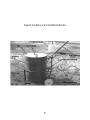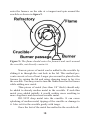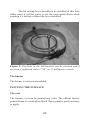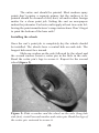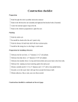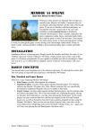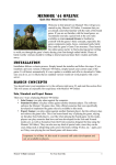
1
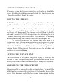
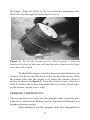
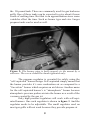
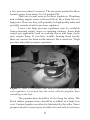
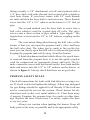
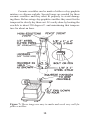
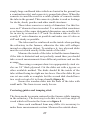
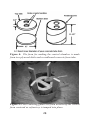
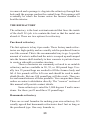
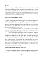
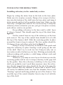
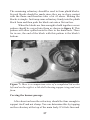
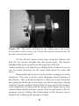
Quick notes for finishing
the furnace kit
REFRACTORY
A form of castable refractory that I have experience with and
recommend is called Kast-o-lite® and is manufactured by; A.P.
Green/ Harbison-Walker. The companies are under the A.N.H
Refractories family of companies. Their website is;
http://www.hwr.com
The Kast-o-lite 26LI is rated to 2600 degrees F. and is
good for a backyard aluminum or bronze melting furnace. For
regular brass or bronze melting you may want to use Kast-olite®
30 which is rated to 3,000 degrees F. The website lists the locations of their distribution centers in the United states where you
can go to purchase the refractory.
If you use Kast-o-lite 26LI two 55 pound bags are needed . If you use the Kast-o-lite 30 two-and-a-half 55 pound bags
of this are needed since it is more dense and fills less volume. These refractories will far out perform the homemade
mixtures.
VARIOUS SUPPLIES
A reliable supplier of foundry supplies for the backyard metalcasting hobbyist and small business is;
www.BudgetCastingSupply.com
CAUTION:
This item is not for use by minors or anyone under the influence of
drugs or alcohol. Melting metal involves danger from extreme heat.
This furnace requires high temperatures to operate which could result
in injury, loss of life or property damage. Burns and unwanted fires
may result especially from careless usage. Safety precautions should
ALWAYS be followed. You are responsible for using this item safely
and keeping the items in safe working order. Use of this item is at
your own risk. Neither the manufacturer, the seller nor anyone affiliated with the manufacturer or the seller is responsible for any damage
or injuries, no matter how minor or major that may result from the
proper or improper use of this foundry equipment and related items.
By purchasing this foundry equipment the buyer agrees to the above
terms and to be solely responsible for his or her usage and the usage
of anyone who uses this unit with or without the buyer’s consent. If
you do not agree to these terms DO NOT use this item. Propane gas
can accumulate and ignite explosively. Propane fumes can cause suffocation from inhaling them. If you have any questions about properly
using or storing propane or other fuel gasses contact your nearest gas
distributor. Safety should ALWAYS come first!
User’s manual and kit assembly instructions for the
HobbyMelter personal foundry furnace
Copyright © 2006 by: Lionel Oliver II
All rights reserved
It is the policy of the producer of this product to improve products as new technology and techniques become available. The
producer of this product reserves the right to revise or otherwise
change this manual at any time without the obligation of notifying any entity, group or person of such revisions. Great effort, attention and care has been taken in the preparation of this manual
and the product(s) described by it. However the producer of this
manual or described product(s) cannot be held responsible for
any ommisions or errors that may be contained or exhibited in
this manual or the described product(s).
Read this ENTIRE manual before beginning. The project will be
much easier that way! Do not try to take shortcuts when completing this kit! Follow the instructions carefully and use the
checklists provided to ensure that all the steps are completed in
the proper sequence.
Once completed this furnace is a powerful tool that has
the potential to make many seemingly impossible projects easily accomplished by providing valuable castings.
KIT ASEMBLY INSTRUCTIONS BEGINS ON PAGE 21.
READ AND UNDERSTAND THIS MANUAL BEFORE
USING THE FURNACE!
Do:
Follow the instructions and safety tips in this manual.
Preheat all metal to be added to the crucible to remove moisture.
Use furnace AWAY from flammable of combustible materials to
avoid fire.
Use furnace over dry sand and level ground.
Use at least a full 10-feet of gas line between the propane tank
and the furnace.
Store the furnace in a dry location sheltered from the weather.
Let the furnace warm up with the lid open if it becomes wet.
Use the furnace in well ventilated areas only. Outdoor is recommended.
Keep onlookers safely away from the furnace.
Keep propane tank in good condition.
Keep children and pets away from hot foundry.
Keep the furnace dry to avoid the need to dry it out.
Pour molten metal over a dry sand or dirt floor.
Comply with all local, state, and federal regulations when operating this equipment.
Do NOT:
Leave the furnace unit unattended while it is in operation.
Operate the furnace without proper safety gear and clothing.
Operate the furnace if it’s not in proper working order.
Modify or attempt to modify the burner for altered gas or flame
output.
Use wet tools around molten metal.
Use this furnace while under the influence of drugs or alcohol,
or while consuming them.
4
MAIN FURNACE COMPONENTS
5
SAFETY CLOTHING AND GEAR
Whenever using the furnace protective work gloves should be
worn. Work boots with laces properly tied, full length jeans and
a long sleeved shirt should be worn.
MOVING THE FURNACE
Do NOT transport or attempt to transport a hot furnace. For safety, allow the furnace unit to cool completely before transporting
it.
The cart’s wheels are designed to assist in transporting
the furnace unit. Tilt the furnace backward raising the front support brace off the ground. The furnace unit will then be able to
roll on it’s wheels. Do NOT attempt to use the lid raising lever as
a handle for rolling the furnace unit. This can result in bending
the hinge mounting bars and severely mis-aligning the lid.
To correctly transport the furnace unit, wait until it is
completely cool. While wearing protective gloves grasp the front
of the side rail with one hand and the back of the hinge with the
other. Use both hands to tilt the unit backward raising the front
support brace off the ground. The unit can now be rolled in this
position as shown in figure 1.
LIFTING THE FURNACE UNIT
The furnace unit is heavy and may cause injury if lifted by one
person. At least two physically able people should lift the completely cool furnace unit simultaneously if lifting it is required.
ASSEMBLING THE FURNACE UNIT
Minor assembly is required for the completed unit. To install the
lid lifting lever remove the clip from it’s hole in the base of the
lever. Slide the round end of the lever onto the mounting stub on
6
the hinge. Align the holes in the lever and the mounting stub.
Slide the clip through the holes and secure it.
Figure 1: To roll the furnace on it’s wheels grasp it with one
hand on the front of the side rail and the other hand on the hinge
area then tilt it back.
To install the burner turn the burner mount thumbscrew
counter-clockwise until the burner tube can fit in the mount. Slide
the burner tube into the mount so it enters the furnace about 2
inches as shown in figure 2. Turn the mount screw clockwise
until it contacts the burner tube and holds it securely. Hand tighten the burner mount screw only.
PROPANE COMPONENTS
The components necessary are; the propane tank, regulator, propane hose, attachment fittings and an optional attachment is a
propane pressure gauge.
Most hobbyists use the propane tank size designated as
7
the 20-pound tank. These are commonly used for gas barbecue
grills. One of these tanks can be expected to give about 6 hours
worth of melting time. But that is an approximation since some
variables effect the time. Such as burner type and size. Larger
propane tanks can be used as well.
Figure 2: The burner pipe is held securely in the mount by a
setscrew. The screw should be hand tightened only.
The propane regulator is essential for safely using the
“self-aspirated” burner design. Self-aspirated simply means that
the burner provides it’s own combustion air as compared to a
“forced-air” burner which requires an air blower. Another name
for the self-aspirated burner’s is “atmospheric” burner because
atmospheric pressure pushes air into the burner as a result of the
vacuum created by the gas jet.
Only high pressure regulators will work with self-aspirated burners. One such regulator is shown in figure 3. And the
regulator needs to be adjustable. The small regulator used on
most gas grills will not work because they provide propane at
8
a low pressure (about 5 ounces). The pressures needed for these
burners range from about 5 to 25 pounds PSI.
There are several sources for these regulators. Plumbing
and welding supply stores will most likely have them but at a
high price. However they will probably be high quality units and
possibly contain a built in pressure regulator.
Lower cost high pressure regulators may be available
from restaurant supply stores or camping catalogs. Some high
output gas appliances such as cooking stoves and large fryers
may require them. If you have trouble locating them locally
there are sources for them on the internet. Do a search for “High
pressure adjustable propane regulator.”
Figure 3: Here is a propane tank and an adjustable high pressure regulator is screwed into the valve with the propane hose
extending to the left.
The propane hose should be 10 feet long for safety. The
black rubber propane hoses should be available at a fairly low
cost. Custom lengths can often be fabricated by the seller. Since
propane dissolves some types of rubber it is not safe to use hoses
9
designed for other gasses such as natural gas or acetylene. Only
hoses specifically designed for propane should be used. The
ends of the hose should have brass fittings that match common
pipe sizes. 1/4” nominal pipe size threads are very convenient.
Sources for hose can also be found on the internet.
A propane pressure gauge is convenient for when you
want to know exactly what pressure your burner is running at.
However it is not necessary. The attachment fittings used will
vary depending on the way you choose to attach the burner to
the propane hose. Two methods are illustrated in figure 4.
Figure 4: There are multiple ways to hookup a propane system.
Here are two common ones.
Both methods begin the same. The adjustable high pressure propane regulator is screwed into the valve of the propane
tank. The gas outlet of the regulator is where the pressure gauge
will be installed (if you choose to use one). If not the propane
hose will screw into this spot.
The way the hose attaches to the burner is where the two
methods differ. In the first method the propane hose has the end
10
fitting (usually a 3/8” attachment) cut off and replaced with a
1/4” hose barb with male threads and secured with a stainless
steel hose clamp. If your hose comes with 1/4” male threads
on each end then the hose barb is not necessary. These threads
screw into the 1/4” x 1/8” reducer on the burner’s 1/8” fuel jet
pipe.
The second method uses the hose barb to screw into a
ball valve which is used for a quick shut off valve. The valve
screws onto a short section of pipe called a “pipe nipple.” The
nipple then screws into the 1/4” to 1/8” reducer coupling on the
burner.
The convenient thing about having the ball valve at the
burner is that you can open the propane tank’s valve and keep
the ball valve shut. The when you’re ready to fire up the furnace you can slowly open this ball valve to release the gas while
keeping the propane tank safely away from the furnace.
A third attachment method which allows for quick burner removal from the propane hose is to use the quick couplers
used for compressed air (pneumatic) hoses and tools. The female connector screws into the threads on the hose barb and the
male end screws into the 1/4” to 1/8” reducer on the burner as
shown in figure 5. Always check that there are no gas leaks.
PROPANE SAFETY RULES
Check all connections for leaks with leak detector or soapy water. If a leak is detected tighten the fittings. Teflon tape designed
for gas fittings should be applied to all threads. If the leak can
not be corrected do not use the system. Check burner for obstructions such as dirt, rust, metal splatter etc. Clear them away
if present. Examine the propane hose for cracks or other damage. Replace the hose if necessary. For safety, replace the hose
every two years.
Always use caution when igniting the burner. Keep all
body parts as far away as possible and wear appropriate safety
11
gear. Keep the propane tank as far from the furnace as possible.
The propane tank should be down wind of the furnace. This will
blow any leaking propane away from the flame if a leak occurred. Always keep the propane tank in an upright position.
Never use a flame to check for gas leaks, keep children
and pets safely away from the hot furnace or operating burner.
Do not use the furnace without a regulator or with an improper
regulator. Keep the propane tank’s valve closed when not in use.
And comply with all local, state, and federal regulations when
operating this equipment.
Figure 5: Quick couplers can be used on the propane line to
make attachment and removal of the burner quick and easy.
TONGS AND CRUCIBLES
There are three main types of crucibles used in a backyard foundry. The most common is a welded steel pot. This is
basically just a section of pipe with a disk welded to the bottom.
The disk should be 1/4” thick. The pipe can be 3 or 4” diameter
12
for a small furnace.
Weld two 1/2” thick 3/4” long sections of steel rod to opposite
sides at the top and a ring at the lower rear. The crucible can now
be lifted straight up and out of the furnace with a special set of
easily made lifting hooks that grab the stubs and ring as shown
in figure 6.
Figure 6: This steel crucible with lugs is very convenient to use
in a backyard foundry, and is easy to make with simple welds.
Small cast iron pots can also work well as a crucible.
Even a welded steel pipe without the stubs or ring will work but
for these crucibles a special set of lifting and pouring tongs are
needed as shown in figure 7.
Iron and steel crucibles work well for normal backyard
metalcasting. However certain aluminum alloys can be contaminated and weakened by iron picked up from the crucible. This
isn’t noticed in decorative or basic hobby metalcasting. However if you want alloys as pure as possible then a ceramic crucible
is best.
13
Ceramic crucibles can be made of either a clay-graphite
mixture or silicone-carbide. Special tongs are needed for these
ceramic crucibles and they must fit properly to avoid damaging them. Before using clay-graphite crucibles they must first be
tempered to slowly dry them out. It’s easily done by heating the
crucible to about 250 degrees F. and maintaining that temperature for about an hour.
Figure 7: These tongs are easy to make and work very well for
plain crucibles.
14
That can be done in the furnace with the burner at a low
setting. Next the crucible is brought to a red heat and allowed to
cool. It is now ready for use. This procedure should be repeated
after long periods of not using the crucible.
Ceramic crucibles can vary by manufacturer but in general
the crucible size is designated by the pounds of molten aluminum it can hold. So a #6 crucible will hold 6 pounds of molten
aluminum.
Steel crucibles conduct heat faster and therefore pass
it on to the metal to be melted quicker but they also oxidize
and can deteriorate quickly if not protected. A product called
“crucible or ladle wash” is available. They are materials that are
brushed onto the steel crucible before each use. The material
protects the steel from oxidation and can also prevent the molten
metal from absorbing steel or iron if this is a concern. Sources
for this material and ceramic crucibles are abundant online.
SETTING UP THE FURNACE
The furnace should only be used in well ventilated areas (outdoors is recommended) and at least 10 feet away from any flammable materials. Use the furnace on level ground on top of a bed
of dry sand or loose dirt.
Do not use the furnace or pour metal over a bare concrete
floor. Molten metal spilling onto concrete will cause moisture in
the concrete to boil into steam and spray chips of concrete and
hot metal.
Ensure that there is enough clearance around the furnace
to walk around easily without obstacles. All molds, metal stock,
tools and propane hose should be neatly organized for easy and
safe access.
A supply of water should always be available to put out
any unwanted fires from wood, paper or similar material. A fire
extinguisher should always be available to put out any unwanted
fires in materials not suitable for water extinguishing.
15
Be sure to wear appropriate safety clothing and gear.
This includes gloves, long sleeved shirt, jeans and work boots.
Safety glasses or a face shield should also be worn. All clothing
must be made of a natural fiber such as cotton. Synthetic fibers
should be avoided since they melt when hot and could cause
severe burns.
DIRECTIONS FOR USING THE FURNACE
Be sure that the furnace unit is in good working order. The lid
raising lever should be installed properly and the burner secured
hand tight in it’s mount. Place the crucible on the plinth block
centered in the furnace (figure 8). Loosely load the metal to be
melted into the crucible. It must be loaded loosely because the
metal expands as it heats up and melts. Tightly loaded metal can
expand and damage the crucible.
Figure 8: Here is the plinth block centered on the furnace floor.
The carved bottom of the block covers the drain hole. The crucible sits on the plinth.
16
With the lid raised prepare to light the furnace. An easy
way to do this is to crumple a piece of newspaper and drop it into
the furnace in front of the burner. With the lid still up off the furnace slowly open the gas valve allowing gas the enter the burner.
The flames should ignite the gas. Turn gas valve as needed for
proper burner functioning.
CAUTION: Igniting the burner with a crumpled wad of
newspaper may result in burning pieces of paper floating out the
furnace.
Once the burner is running properly lower the lid into
position. If the burner did not ignite before the paper burned
out allow the furnace to air out the gas fumes then repeat the
procedure. If the flame extinguishes CLOSE THE GAS VALVE
IMMEDIATELY. Let the furnace air out and then relight it.
If the burner will not stay lit the gas pressure at the regulator may be too high. Turn it down and retry the burner. On cold
or windy days it may be difficult to ignite the burner reliably. In
this situation you can soak a piece of charcoal in charcoal lighter
fluid and ignite it in front of the burner. This burning charcoal
should keep the flame burning until the furnace is warmed up.
Let the burner run at a lower flame setting for 2 minutes to heat
the furnace before turning it up to full operating flame.
If the burner produces a pulsating, “woopf… woopf…
woopf...” type of sound there may be too much back pressure
in the furnace. Try sliding the burner backward away from the
chamber. If that does not solve the problem the gas pressure may
be incorrect. The burner sound should be like a smooth sound of
“rushing wind” or like a large torch.
Once the furnace is warmed up turn the burner up to
full operating flame and allow the metal in the crucible to begin
melting. At this point any other metal to be added to the crucible
must be preheated by setting it on the furnace lid near the vent
hole. Do not obscure the vent hole as this can cause excessive
back pressure in the furnace and blow out the burner’s flame. The flame should not be pointed at the crucible. It should
17
enter the furnace on the side at a tangent and spin around the
crucible as shown in figure 9.
Figure 9: The flame should enter the furnace and swirl around
the crucible, not directly contact it.
Narrow pieces of metal can be added to the crucible by
sliding it in through the vent hole in the lid. This method prevents excessive loss of heat. Larger pieces must be placed in the
furnace by raising the lid and using charging tongs to lay it in
the crucible. You may want to turn the flame down on the burner
while adding new metal.
Thin pieces of metal (less than 1/8” thick) should only
be added to already molten metal in the crucible. If such thin
metal were added initially it would oxidize more resulting in
more slag/dross and decreased useable metal.
DO NOT drop metal into the crucible. It can cause
splashing of molten metal, tipping of the crucible or damage to
it. Also set it in the crucible gently with tongs.
Once the last of the metal has melted in the crucible all18
ow it to sit in the heat an additional 3 minutes for aluminum and
4 to 5 minutes for brass/bronze. This process “super heats” the
metal above it’s melting temperature making it less likely to cool
and solidify before the mold fills.
After the super heat, it is skimmed with the skimming
tool to remove slag/dross from the surface. If melting is complete close the gas line to shut off the burner, remove the crucible and pour the metal, (figure 10).
Figure 10: Pouring the metal with a simple set of pouring hooks
designed to grasp two lugs.
Ingot molds should always be available to accept the extra metal left over from pouring a mold. Ingots are simply blocks
of clean metal. They can be stored easier than the plain scrap and
can be put into a crucible as melting stock. Steel cupcake pans
are popular for making small ingots. With some coated pans the
ingots stick until the pan gets a layer or rust on it. Ingot molds
can also be welded together from sections of angle iron. The
size of the ingots should be what will easily fit in the crucible.
19
It is recommended that the burner be removed from the
hot furnace after shutting it down to prevent it from absorbing
excess heat and being damaged.
When the propane tank comes close to empty a layer of
frost will form on the bottom of the tank and the gas pressure
will decrease. Propane gas is stored in liquid form and once the
valve is opened it rapidly vaporizes into the useful vaporous
form. To help solve this “freeze-up” problem the tank can be
placed in a tub of warm water. NEVER try to heat a gas tank
with flames, exhaust from the furnace or by setting the tank on
or near the furnace.
DRYING OUT THE FURNACE
The furnace should always be kept dry. The drying procedure
should be performed before the first use of the furnace, after a
long period of disuse or if the furnace becomes very wet.
To dry the furnace safely attach the propane components
to the burner. Install the burner in the burner mount and raise the
furnace lid. Ignite the burner and let it heat the furnace chamber
for at least ten minutes with the lid up. Lower the lid and allow
the furnace to cool. This procedure prevents a buildup of steam
pressure within the refractory which can blow out pieces of the
refractory. Hairline cracks in the refractory are normal.
CLOSING WORDS
With your new furnace you have the potential to create a multitude of castings from otherwise useless scrap. Whether your
goal is to cast artistic pieces, machine or model parts, pieces to
an invention, “knick-knacks” or even items to sell, you have the
equipment to do the job. Additional study and practice and maybe even added tools and materials will increase your potential
and you may soon realize that you can do much more than once
imagined. Have fun with your foundry and happy metalcasting!
20
KIT ASSEMBLY
INSTRUCTION
MANUAL
CAUTION!
SHEET METAL HAS SHARP EDGES, WEAR GLOVES!
21
FURNACE BUILDING KIT INSTRUCTIONS
INSPECTING THE PACKAGE CONTENTS
After receiving the package inspect all the contents. Most of the
kit is assembled so it’s more of just a matter of organizing everything to work on it. It is recommended that the kit be completed
in the following steps;
1. Assemble brackets and fittings, tighten bolts.
2. Paint the furnace shell and cart.
3. Fill lid and furnace shell with refractory.
4.Cure the refractory lining.
ASSEMBLING THE HARDWARE
Lid assembly
These steps are simple. On opposite sides of the lid form there
are “T” shaped brackets installed. Using two 7/16” or 11 millimeter wrenches tighten the bolts completely.
Next install the internal support ring through the holes
centered in the lid form. About an 1/8” of the ring’s mounting
arms should extend out the sides of the lid form through the
holes in the brackets. Figure 1. The lid can be set aside for now.
Main body assembly
There is no assembly needed for the main body.
The furnace cart
Until the cart is painted it should not be fully assembled. The
wheels should not be on the cart during painting unless you want
them painted also.
22
The lid raising lever should not be installed at this time
either since it will be easier to set the cart upside down while
painting it’s bottom without the lever installed.
Figure 1: The bolts in the lid brackets can be checked and if
necessary, tightened with a 7/16” or 11 millimeter wrench.
The burner
The burner is sent pre-assembled.
PAINTING THE FURNACE
The cart
The furnace cart can be painted any color. The official factory
paint scheme is a semi-gloss black. Spray paint is quick and easy
to apply.
23
The entire cart should be painted. Most modern spray
paints don’t require a separate primer, but the surfaces to be
painted should be cleaned of dirt, dust, oil and/or other foreign
matter for a clean paint job. Setting the cart on newspapers
makes the job neater. For best results apply at least two coats following the paint manufacturer’s usage instructions. Don’t forget
to paint the bottom of the base rails!
Installing the wheels
Once the cart’s paint job is completely dry the wheels should
be installed. The wheels have a central hub on each side. The
longest hub must face inward.
Slide one washer on the axle followed by the wheel and
the second washer. Insert a cotter pin in the hole in the axle.
Bend the cotter pin’s legs to secure it. Repeat for the second
wheel (figure 2).
Figure 2: Slide a washer and the wheel on the axle (long hub
side first), install second washer and cotter pin. Bend the legs of
the cotter pin outward to secure it.
24
Installing the lid raising lever
Remove the locking pin from the hole in the lever. Slide the
round end of the lever onto the mounting stub welded to the
cart’s hinge. Align the holes in the lever and the stub. Slide the
locking pin through the holes and secure the pin’s clip.
Painting the furnace body and lid shells
Since the furnace shell can become very warm and even hot
during furnace usage, regular paint may burn away. It’s best to
use a heat resistant paint. These paints are designed for use on
barbecue grills, fireplace stoves and other hot objects. Only the
outside of the shell must be painted.
Set the lid shell on a sheet of newspaper and spray the
heat resistant paint on the outside. Also spray the lid brackets.
The internal support ring should not be painted.
INSTALLING THE REFRACTORY
Before any refractory can be installed the inner forms must be
made. The refractory is packed in around these forms. When the
forms are removed they leave the necessary hollow areas (chamber, vent and drain) in the refractory lining.
The lid’s vent form
The finished lid has a 3-1/2” diameter hole through the center to
allow exhaust gasses to escape from. The form can be as simple as a 3-1/2” outer diameter section of sturdy mailing tube as
in figure 3. You can even roll some flat cardboard into a tube.
Nearly any 3-1/2” diameter cylindrical object could work. If a
cardboard tube is used (probably the best choice) then it should
be cut to 2-1/2 inches tall to match the height of the lid.
25
The main body chamber forms
The drain form
The main body of the furnace requires two forms. The first is for
the drain hole which passes through the base, This hole drains
away molten metal in case a crucible ever breaks or spills in the
furnace. This form is similar to the lid’s vent form but it is only
2” outside diameter and should be 2-1/2” tall, figure 3 again.
Figure3: The lid vent and drain forms are simple shapes and
can be cut from appropriately sized mailing tubes.
The chamber form
The inner chamber of the furnace is 8” in diameter and 11-1/2”
deep. Therefore the chamber form must also be 8” in diameter
and be 11-1/2” tall. I’ve discovered that the easiest way to make
the form is to start with a pre-made concrete form tube. These
are sold in hardware and home improvement stores. They are
26
simply large cardboard tubes which are buried in the ground (on
a construction site) and concrete is poured into them. When the
concrete is cured the result is a solid cylinder of concrete inside
the tube in the ground. This concrete cylinder is used as footings
for decks, sheds, porches and other small structures.
These tubes come in a variety of diameters. For this furnace an 8” diameter form is needed. I’ve noticed that sometimes
even forms of the same designated dimension can actually differ in size by as much as 1/4” inch. So obtain a tube as close to
exactly 8” outer diameter as possible and make sure it’s also as
stiff and sturdy as possible.
The tube must be reinforced on the inside when packing
the refractory in the furnace, otherwise the tube will collapse
inward or otherwise distort. To reinforce it, two plywood disks
must be cut which exactly fit the inside of the tube.
Measure the inside of the tube to find the inner diameter,
if the tube is distorted and not perfectly round then you should
take several measurements from different positions and use the
average.
Then using a compass draw two appropriately sized circles on 3/4” thick plywood. Cut the disks out with a jig saw or
other available method. The disks should fit the inside of the
tube without being too tight nor too loose. Once the disks fit you
can set one aside as complete but the second disk should have
two ovals cut out of it to form a handle (figure 4).
Secure the wooden disks into the ends of the tube with
small nails. The form is now ready for use.
Centering guides and tamping stick
The form needs to remain centered in the furnace while tamping
in the refractory. The best way to do this is to cut four strips of
wood which will center the form as in figure 5.
Since each cardboard form may differ it is necessary to
make these measurements custom. Measure the outside diam27
Figure 4: The form for making the central chamber is made
from two plywood disks and a cardboard concrete form tube.
Figure 5: Four centering guides cut from wood keep the central
form centered as refractory is tamped into place.
28
eter of the central form and note the measurement. Since the
inside of the furnace body shell is 13”, subtract the forms outer
diameter from 13”. Divide the result by two. This is how wide
each centering guide should be.
For example, if the outside of your form is exactly 8”
diameter then subtract 8” from 13” (the inside diameter of the
sheet metal body shell) the equation is;
13 - 8 = 5 then divide 5 by 2
5/2 = 2.5
Therefore the centering guides should be 2.5 inches wide and a
good length for them is 14”.
The tamping stick can be as simple as another piece of
plywood cut to the size of the centering guides. All you need is
a piece of material that you can use to tamp the refractory in the
gap between the sheet metal shell and the central form.
Plinth block form
A plinth block is just a circular “brick” of refractory that is set in
the bottom of the furnace and the crucible is set on top of it. The
blocks are 3-1/2 to 4” diameter and 1-1/2” tall. A short section of
3-1/2 or 4” diameter plastic tubing, pipe or cardboard tube will
work well for forming them.
Preparing the furnace shell
One last step is necessary before the refractory can be mixed
and installed in the shell. The tuyere (tweere) hole cut into the
lower section of the furnace must be completely covered with
tape. Duct tape is the best for the job since it sticks securely and
is waterproof. The tape stops the refractory from squeezing out
of this hole. Once the refractory has started to harden the tape
29
is removed and a passage is dug into the refractory through this
hole until the passage reaches the central form. This passage will
eventually be where the burner enters the furnace chamber to
heat the interior.
THE REFRACTORY
The refractory is the heat resistant material that lines the inside
of the shell. It’s job is to contain the heat so that the metal can
absorb it. There are two options for refractory.
Purchased refractory
The first option is to buy it pre-made. These factory made refractories are high quality and are usually sold in powdered form in
sacs like cement. This is the recommended way to go. A specific
amount of water is added and the mix is scooped up and tamped
into the furnace shell similarly to how concrete is put into forms
to create a sidewalk or similar structure.
These refractories are commonly referred to as castable
refractory and are available in 50, 55, or 100 pound bags. Usually two 55 pound bags are needed to fill the furnace body and
lid. A few pounds will be left over and should be used to make
plinth blocks. But one 100 pound bag will also work. There are
several manufacturers of these products. You can purchase them
online or contact a distributor directly. The “sources” section of
this manual will provide contact details.
Some refractory is rated for 3,000 degrees F and is more
dense. For these you’ll need three 55 pound bags.
Homemade refractory
There are several formulas for making your own refractory. It’s
usually agreed that homemade refractories don’t last as long as
the purchased type. One easy formula is;
30
Portland cement (1.5 parts)
Silica Sand (2 parts)
Perlite (1.5 parts)
Fireclay (2 parts)
A small bucket (2 gallon size) is the best thing to measure the
components with. So since the sand calls for “2 parts” you’d use
two buckets worth of sand. Portland cement would be 1.5 buckets worth. All using the same 2 gallon size bucket.
In case you’re unfamiliar with some of the components
here is some information.
Portland cement is plain cement powder and specifically says
Portland cement on the package. It is mixed with sand and gravel to make concrete. It is also the main component in brick mortar. Portland cement should NOT be confused with “masonry
cement” which usually has other components mixed in with it.
You want plain Portland cement. It’s available at home improvement stores and masonry supply dealers. It is usually sold inexpensively in 96 pound sacs. One sac is more than sufficient.
Silica sand is the same type of sand found at the average beach.
It is also the type of sand used to make concrete or brick mortar.
It is sometimes called “builder’s sand.” The best place to get
clean silica sand is a home improvement store or masonry supply dealer. It is usually sold inexpensively in 50 pound sacs. Two
sacs will be enough. Perlite is a white, light-weight, odorless, sterilized, heat-expanded volcanic mineral. It’s used in potting soil to loosen and aerate
the soil. It works well in the refractory because it does not conduct heat well. Therefore more of the heat stays in the furnace
where the metal can absorb it. It also makes the refractory lighter
weight. The best place to buy perlite is a garden supply store. It
is usually sold in bags containing 8 dry quarts. Four bags will do
31
the job.
Fireclay is a type of clay sold in dry powdered form. It is available from ceramics or some masonry supply dealers in 50 pound
bags. One bag will do the job. For some reason some people in
various areas of the country have trouble finding fireclay. Do not
let anyone convince you that a product called “furnace cement”
is fireclay. Fireclay is called Fireclay.
MIXING THE REFRACTORY
The best tools to mix the refractory with is a small hoe and shovel. The hoe will do the majority of the work of mashing the mix
back and forth until it is evenly blended. A plastic concrete mixing tub is an ideal container to mix the materials in. A large tub
about 4-feet long will hold the materials fairly easily, the smaller
tubs may be harder to work with.
It’s recommended that you wear rubber gloves when
working with refractory. Since it is a form of concrete it can
easy dry out your skin if left on it.
Since both the purchased castable refractory and the
homemade refractory harden like concrete all your tools, the
furnace shell and lid, and all forms must be ready and in position before you begin mixing the refractory. And also for this
reason it is best not to begin mixing the refractory when you are
tired, otherwise you may want to take a break when you should
instead just finish the job. Also since you need to return after an
hour or two to cut the tuyere passage, you don’t want to risk falling asleep or forgetting to do so and ending up with rock hard
refractory and no tuyere passage!
Mixing purchased, castable refractory
The factory made purchased refractory should be mixed according to the manufacturer’s instructions. It will most likely be
32
a looser mix than the homemade refractory which should be
rather stiff. And like concrete it can harden rather rapidly (within
2 hours). So once it is mixed it needs to be installed without
delay.
Mixing the homemade refractory
All your tools, the furnace shell and lid with forms must be ready
and in position before you begin mixing the refractory.
The homemade refractory should be mixed in a specific
order. Start by completely mixing the Portland cement, sand and
perlite. These should be mixed while dry. It is likely that the
sand will have some moisture in it and that is ok.
Be sure that these three components are completely
blended and there are no spots of unmixed material.
Add a small amount of water. Very little water is needed, the amount varies depending on the moisture content of the
sand. But you only want the mixture to be damp. It should be
fairly stiff and clumpy.
Add the fireclay to the damp mixture. Mix it thoroughly
until the mixture is completely uniform. Add just enough water
to keep the mixture moist but still somewhat stiff. You DO NOT
want a wet, soggy mixture. However it you get it a little too wet
and the mix ends up very “gooey” and extremely sticky then it’ll
still work but it’ll be more of a challenge to tamp into place.
The less water that you need to use the better. Because as
the refractory dries, and especially when it is heat cured it will
form small cracks. All refractory forms some cracks, hairline
cracks are normal and are no problem but a mixture that is too
wet is more likely to shrink and crack severely since there is so
much more water that needs to evaporate out.
Once the refractory is completely mixed it should be
tamped into the furnace shell without delay since it begins to
harden with the cement in it.
33
INSTALLING THE REFRACTORY
Installing refractory in the main body section
Begin by setting the drain form in the hole in the base plate.
Make sure it is in place securely. Dump a few scoops of refractory into the bottom of the shell onto the base plate and tamp it
down smooth and level all around the drain form. Make sure the
form stay’s straight and centered. It is not necessary to tamp the
refractory down as hard as you can, just get it in place securely
and with no voids or air pockets.
Keep adding refractory to the base until a solid layer
2” deep is formed. This should equal the top of the drain form,
figure 6.
Set the central form on top of the refractory in the base
and center it. The top of the central form should be level with
the top of the furnace shell. Slide the centering guides in place
around the form to keep it centered. The four guides should be
90 degrees from each other, refer back to figure 5.
Dump a scoop of refractory in between each guide and
tamp the refractory in place forming a wall going up the side
of the shell. Don’t try to work too fast. Tamp in only one or
two inches worth of refractory at a time. Working systematically
without rushing will produce a solid lining without voids and
that is what you want.
Whenever you tamp in a new layer of refractory raise the
centering guides and be sure to temp refractory in the gaps left
by the guides. Once the refractory is halfway to the top of the
shell you probably won’t need them anymore since the refractory already tamped into place should do the job of keeping the
form centered. But stay mindful to ensure that it doesn’t sway
off center. In addition make sure that the chamber form is not
“floating” upward and being pushed up out of the furnace. You
need the top of the central chamber form to stay level with the
top of the shell. 34
Figure 6: The base is tamped in and must bee smoothened off
before adding the central form seen on the left. Notice the void
left by the drain form.
When the refractory lining is completely installed in
the shell, the resulting furnace body will be very heavy (70+
pounds). So it is a good idea to slide the furnace shell into the
cart when the refractory is only half complete. The reason it’s
done now rather than in the very beginning is because the furnace needed to be on a flat surface initially to keep the drain
form from being pushed down out the hole in the base.
The seam in the furnace shell is to the back of the furnace. Raise the body up and slide it into position in the furnace
cart. It will be necessary to first insert the furnace with the seam
facing one corner so that the base fasteners will slide through
the gaps in the corners of the side rail. Then once in the cart the
furnace is twisted into the proper angle. With the shell in place
in the cart you can continue tamping in the refractory without
worrying about lifting a heavy furnace into place.
35
Once the refractory has been tamped in all the way to the top,
use your ramming stick or other suitable tool to scrape or “strike
off” the top nice and flat. The main body is complete for now.
Cover it with a sheet of plastic so it can begin it’s chemical curing without drying too fast.
In an hour or two you must check the refractory for stiffness. Because once the refractory is stiff enough to support itself
without slumping you need to remove the duct tape from over
the tuyere hole and carve out the burner passage.
Installing refractory in the lid section
The lid will be completed much quicker than the main body, but
the same focus and effort needs to be put into the lid to ensure it
is made with solid refractory and without voids.
Starts by ensuring that the internal support ring is centered in the lid shell. The shell should be round without kinks
and on a flat surface. The support ring should be horizontal and
an equal length of the ring’s mounting arms extend out of the
brackets on each side of the lid form.
Set the lid’s vent form in the center of the lid within the
support ring (figure 7). Dump some refractory into the lid form
and begin tamping it all around inside the form. Be sure that the
refractory makes solid contact with the surface that the lid is setting on. This will ensure a solid bottom surface of the lid.
Dump in another scoop of refractory and tamp it in. The
support ring must be completely surrounded by refractory. As
with the main body, the goal is to form a solid mass of refractory
in the form without voids or air pockets.
Once the lid form is filled strike off the top surface flat.
Cover the lid with a sheet of plastic so it can begin it’s chemical
curing without drying too fast.
The plinth blocks
36
The remaining refractory should be used to form plinth blocks.
Several blocks should be made since they are in close contact
with the flame and therefore take a lot of abuse. Making the
blocks is simple. Just tamp some refractory firmly into the plinth
block form and then push the block out onto a flat surface.
When the blocks are firm enough to hold together a cross
pattern should be carved into them as shown in figure 8. This
pattern will allow spilled metal to flow to the drain hole. There
for in use, the end of the block with this pattern is the block’s
bottom.
Figure 7: Here is a comparison view of a completed lid on the
left and on the right is a lid shell showing support ring and vent
form.
Carving the burner passage
After about an hour the refractory should be firm enough to
support itself and not slump. You can determine this by tapping
on the refractory at the top of the main body. If it feels firm and
37
when you tap on it your finger does not push into it then it is
ready.
Remove the tape from the tuyere hole. Using a spoon,
dull knife or similar tool carve out the refractory directly visible
in the tuyere hole. Carve the refractory away forming a passage
the same width and height as the tuyere hole all the way to the
central form.
The tricky part is to carve the passage at a tangent to the
chamber form. When done correctly the passage will have the
same oblong shape that the tuyere hole has as shown in figure 9.
Once this is done allow the refractory in the main body
and the lid to cure and harden for at minimum 3 days. If you
have the patience to wait a week then that’s even better.
Figure 8: The plinth blocks are easy shapes to form using a section of pipe or tube as a mold and carving the channels.
38
Figure 9: The tape must be removed from the tuyere hole and
the burner passage carved in the refractory before it’s too hard.
FIRING THE LINING
Whether you used a purchased refractory or a homemade one
it is necessary to SLOWLY heat the refractory to remove the
moisture from it. If you do this step too quickly the moisture in
the refractory could build up intense steam pressures internally
which can blow out chunks of the refractory.
Therefore a slow “simmering” type fire is needed. The
easiest way to accomplish this is to light a fire of wood and paper in the bottom of the furnace. The fire will probably create a
noticeable amount of smoke so if you’re in a sensitive area you
may want to instead use barbecue grill type charcoal.
Punch a hole in the chamber form by pushing a sharp
object through the tuyere hole passage. This will help air to pass
through. If you can manage to remove the top plywood disk
from the form without damaging the refractory then you’ll have
39
an even easier time at firing the lining. Otherwise it’ll just burn
out, or you’ll be able to remove it with a wire hook after a few
minutes of the fire burning away the cardboard form tube.
Keep adding cardboard, dried twigs and other thin pieces
of wood to the fire for about ten minutes once there is a nice
blaze going. At this point the lid should NOT be on the furnace,
the goal is to give the main body a chance to get an initial drying.
Let the fire burn out completely and let the furnace cool
completely. Once cool clean out any ashes and coals. Inspect the
lining of the furnace. The central form should be burned away
except possibly for part of the bottom plywood disk. It should be
possible for you to remove the remaining section of this disk by
installing a screw and lifting it out.
If there are any flaws in the lining a small batch of refractory can be mixed and packed into them before the firing is
completed. Before beginning the next firing step the lid should
be installed on the furnace. To install the lid set it on the furnace body with it’s seem also facing back. Align the holes in the
brackets on the lid lifting arms with the holes in the lid brackets.
Install the bracketry hardware in the way shown in figure 10.
If the lid lifting lever is not already installed, do so now.
Press down on the lever until it contacts the ground to hold the
lid up. If the furnace was scratched while installing it in the cart
it can be touched up with the spray paint.
After patching the flaws, if any, and installing the lid,
begin the slow firing process again with a wood, cardboard and
paper fire. Get a nice blazing fire going.
Drop some charcoal into the furnace until the furnace is
about half full. Once all the coals have ignited lower the lid into
position on the furnace. Let the furnace sit this way for an hour
so the heat can begin slowly drying the lid.
For the final firing of the furnace you will need a small
air blower. A handheld hair dryer will work and if used, it should
be set on a setting where only air will blow out without heat.
This will preserve the life of the hair dryer.
40
Figure 10: The lid is attached to the lifting arm with a pin,
two washers and a cotter pin. Notice the spacer between the lid
bracket and arm bracket.
Set the blower about a foot away from the furnace but
aim the air stream straight into the tuyere hole. The flames
should really pick up and start blowing out of the lid.
At this point you can either keep adding sticks to the fire or you
can use more charcoal. As the sticks burn down to coals add
more.
During this time a lot of steam will be coming out of the
refractory. You may even see water dripping out the bottom of
the furnace. This is all normal and it is what you want. Keep this
fire going for about one or two hours or until steam stops coming
from the furnace and lid. Shut off the blower and let the furnace
cool completely. At this point the firing of the lining can be considered done and the furnace can be used to melt metal with it’s
propane system. Follow the instructions in the furnace user’s
manual for setting up the propane system.
41
Inspect the lining again after the furnace has completely
cooled. Most likely some hairline cracks will have formed. This
is normal and is nothing to be concerned about. Cracks form
is every type of refractory. It’s a consequence of the refractory
requiring water for mixing and the water evaporating out. This
helps to explain why adding too much water is not good for the
refractory.
THE KIT IS COMPLETE
After the refractory is completely cured the kit is complete. The
propane burner can be installed and the propane line and other
components can be connected. Refer to the furnace user’s manual for instructions in this stage.
Additional Assistance
If you have any questions about the furnace kit, usage, or metalcasting in general visit; www.BackyardMetalcasting.com
On the website there is an abundance of metalcasting information and examples as well as a message forum where metalcasters of all experience levels can post questions comments
of photos of their backyard foundry!
Closing words
With you new foundry furnace you have the potential to create a multitude of castings from otherwise useless scrap metal.
Whether your goal is to cast artistic pieces, machinery components, model parts, pieces to an invention, decorative “knickknacks” or even items to sell, you have the equipment to do the
job. Additional study in the topic as well as practice and maybe
even added tools and materials will increase your potential and
you may soon realize that you can do much more than once
imagined. Have fun with your foundry and happy metalcasting!
42