1
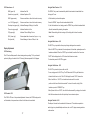
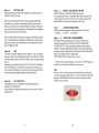
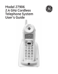
Base Underside Features & Controls 26. 27. 28. 29. 30. 31. 32. 33. 34. 35. 36. 37. 38. 39. 40. LP550 User’s Guide Line Powered Speakerphone Single Line Caller ID 39 40 26 27 28 Data port receptacle Line cord receptacle Headset port receptacles Handset coil cord receptacle Ringer Volume - HI LOW OFF Message Waiting - NEON LED Hold setting - LINE SYSTEM Handset cord channel Model version number Line cord channel Warranty seal Mount bracket lock Mount bracket channel Desk mounted bracket Wall mounted bracket 29 38 37 36 35 5025 Galley Road Colorado Springs Colorado 80915 USA 1.800.462.9446 domestic +1.719.638.8821 international www.telematrixusa.com 34 1.800.462.9446 domestic +1.719.638.8821 international www.telematrixusa.com 30 31 32 33 TABLE of CONTENTS: STATEMENT OF LIMITED WARRANTY TELEMATRIX, INC.. warrants to its [original end customer] [purchaser] that Spectrum PLUS, Marquis and RETRO branded products manufactured by TELEMATRIX, INC. are free from defects in materials and workmanship for ve (5) years after the date of purchase, and Regency branded products manufactured by TELEMATRIX, INC. are free from defects in materials and workmanship for three (3) years, other than the following products for which the warranty period shall be one (1) year: handset batteries, either NiCd or NiMH, used in TELEMATRIX, INC. cordless products. If a product fails this warranty during the warranty period, TELEMATRIX, INC. will, at its option, either repair or replace the defective product or parts, or deliver replacements for defective products or parts on an exchange basis at no additional charge to the customer except as set forth below. Repair parts or replacement products may be either new or reconditioned. Products or parts returned to TELEMATRIX, INC. under this warranty will become the property of TELEMATRIX, INC. Warranties on products repaired by TELEMATRIX, INC. expire at the termination of the original warranty period. This limited warranty does not cover 1. 2. 3. 4. 5. 6. 7. 8. Products or parts which are damaged, abused or misused; Any damage resulting from improper installation, maintenance or operation of the product; Damage resulting from unauthorized modication or repair of the product, or from improper connection of the product to other equipment; Cords, connectors and replaceable batteries; Damage in transit to the TELEMATRIX, INC. repair facility; Any product or part unless proof of date of purchase is submitted with the product when returned for warranty repair; or Costs incurred by the customer in removing and shipping the product to TELEMATRIX, INC. for repair or replacement, and costs of reinstallation of the product. Products or parts which are not owned and used by the original end user customer. The cost and risk of loss or damage for sending the product to TELEMATRIX, INC. will be borne by the customer. TELEMATRIX, INC. EXPRESSLY DISCLAIMS ALL WARRANTIES EXCEPT THE LIMITED WARRANTY SET FORTH HEREIN, WHICH IS THE SOLE AND EXCLUSIVE WARRANTY OF THE PRODUCT, AND IS IN LIEU OF ALL OTHER WARRANTIES, WHETHER ORAL OR WRITTEN, EXPRESS OR IMPLIED, OR STATUTORY. THERE ARE NO IMPLIED WARRANTIES OF MERCHANTABILITY OR FITNESS FOR A PARTICULAR PURPOSE. THE CUSTOMER’S SOLE REMEDY UNDER THE TELEMATRIX, INC. WARRANTY SHALL BE REPAIR OR REPLACEMENT AS PROVIDED ABOVE. IN NO EVENT WILL TELEMATRIX, INC. BE LIABLE TO CUSTOMER OR ANY OTHER PARTY FOR ANY INDIRECT, INCIDENTAL OR CONSEQUENTIAL DAMAGES, INCLUDING, WITHOUT LIMITATION, DAMAGES OF LOST PROFITS, LOST REVENUES, LOSS OF USE OF FACILITIES OR EQUIPMENT, OR COST OF SUBSTITUTE EQUIPMENT ARISING OUT OF THE USE OR INABILITY TO USE THIS PRODUCT, EVEN IF THE CUSTOMER HAS ADVISED TELEMATRIX, INC. OF THE POSSIBILITY OF SUCH DAMAGES. TELEMATRIX, INC. LIABILITY FOR DAMAGES SHALL NOT EXCEED THE PURCHASE PRICE OF THE DEFECTIVE PRODUCT. This limited warranty is non-transferable without the prior written approval of TELEMATRIX, INC. It gives the customer specic legal rights. The customer may have other rights which vary under local law. Some jurisdictions may not allow limitations on the term of an implied warranty or exclusions or limitations of incidental or consequential damages. SpectrumPLUS LP550 INSTALLATION & USERS GUIDE PARTS CHECK LIST: The following parts are included in this package: A. Line cord - 15 ft.* B. Handset coiled cord - 10ft. C. Base unit D. Handset E. Twenty two (22) speed dial preprinted keycaps F. Four (4) additional clear keycaps G. Two (2) labeling sheets H. Wall/Desk Mount Wedge and short 6 inch line cord.* * SpectrumPLUS line cords are 4-pin 6-conductor line cords (4P4C line cord). Replacement line cords must be the same. COMPLIANCE & SAFETY: Features Features & Controls Parts List Compliiance/Safety page 1 page 2 page 2 Installation Caution Information Connecting Cords Key Caps Switch Settings (hold, ringer, msg. waiting) Bracket - Desk or Wall Mounting page 3 page 3 page 3 page 4 page 14 Operation LED Indicators Placing a Call Data Port Hold/Mute & Redial Features Disconnect & Volume Features VoiceMail Retrieval & Recording Headset Features page 5 page 5 page 5 page 6 page 7 page 7 page 8 Programming All Functions Date/Time, Language, Voice Mail Dial Key, Call Waiting ON Pause & Flash Timing Live Dial Pad, SDT, All Setup Ok page 9 page 10 page 11 page 12 page 13 LCD Display Information & Icons LCD Display Images page 15 LCD Information pages 16-20 Servicing Care, Maintenance, Service Warranty page 21 page 22 As specied by FCC regulation, we are required to inform you of specic governmental and compliance regulatory requirements, safety notices, safety instructions and other informative information. TeleMatrix, Inc.. provides this information in a separate manual. We place the separate Compliance and Safety Manual within each outer box or product box when shipped. Prior to reading this operation manual and prior to setting up your telephone, please refer to the Compliance and Safety Manual. If the Compliance and Safety Manual is not immediately available. Please obtain a free copy by calling our PriorityCare department (1.800.462.9446) or by downloading a copy on our Internet web site (www.telematrixusa.com). 21 2 * Version 08.24.07 Installation... Call Record Editing Prior to Dialing Caution Information • Never install telephone or network wiring during a lightning storm. To Add Characters to the Displayed Number • Never install telephone or Ethernet jacks in wet locations unless the jack is specically designed for wet locations. 1. Press the “↑” or “↓” key to activate the display for scrolling. • Never touch uninstalled telephone wires or terminals unless the telephone line has been disconnected at the network interface. 3. Activate the editing feature by pressing any number on the keypad. (note that the key • Use caution when installing or modifying telephone and network lines. 2. Scroll to the number you wish to dial. pressed will be displayed on the LCD). 4. Press the keypad number you require and it will appear on the LCD prior to the number on the display. Connecting the Handset Cord A 10 ft. modular handset coil cord is provided. To install, simply plug one end of the coil cord into the jack at the base of the handset, and the other end into the jack located on the under side of the telephone base marked “Handset”, routing the long end of the cord through the channel directly below the jack. 5. To dial, lift handset or activate the “SPEAKER” key or press “DIAL” key to dial number automatically. When pressing the “DIAL” key, the “SPEAKER” will activate. Note: The number can only be inserted prior to the displayed digits. To Delete Characters to the Displayed Number 1. Press the “↑” or “↓” key to activate the display for scrolling. Connecting the Line Cord A 15 ft. modular line cord is provided. To install, simply plug one end of the cord into the modular jack on the underside of the base unit, route the line through the channel directly below the jack, and the other end into the wall jack. 2. Scroll to the number you wish to dial. 3. Activate the editing feature by pressing any number on the keypad. (note that the key pressed will be displayed on the LCD). 4. Press the “DELETE” key to delete invidual characters. 5. To dial, lift handset or activate the “SPEAKER” key or press “DIAL” key to dial number Installing Key Caps Twenty two pre-labeled feature keycaps are provided. automatically. When pressing the “DIAL” key, the “SPEAKER” will activate. There are eleven clear keycaps already installed. To install pre-printed keys, remove the Note: When deleting characters from a caller’s identity, the Call Log will not be changed. clear caps by pulling up. Replace with pre-printed caps or place user printed paper index labels under a clear keycap. Program each speed dial key for the specic function of the “Invalid Entry” Displayed - # key. (See Programming page 9-16 for instructions) Indicates that the entry is not recognized or is outside the parameter of the range for that specic function. LCD display the “INVALID ENTRY”. Labeled Key Caps The twenty two silkscreened keycap names are below: Call Fwd On Call Fwd Off Transfer Emergency Rpt Mag Call Back Paging Cancel Call Back Call Park Call Pick-up Group Call Pick-up Paging Ring Again Save Msg Del Msg 3 Skip Msg FF Msg Rew Msg DND Information 911 Conf Help Desk 20 Settings... Deleting a Call Log Record Deleting an individual stored Call Record Press “↑” or “↓” key to activate stored memory. The LCD screen will display a record. Scroll to the record you wish to delete. Press the “DELETE” key once and the LCD screen will display the question “DELETE?” Press the “DELETE” key a second time to delete record. Ringer Volume Switch - # 30 The ring volume switch can be set at High, Low or Off position. Message Waiting Selector - # 31 This telephone can support 90VDC “Neon” or low-voltage “LED” message waiting systems. Simply slide the switch to the desired position that is compatible with your PBX message system. Deleting All stored Call Records Press “↑” or “↓” key to activate stored memory. croll to the rst record in memory. Press and hold the “DELETE” key for 6 seconds. The LCD will display the question “DELETE ALL?” To delete all stored calls, release and press the “DELETE” key again to delete all records. Note: the phone is factory preset to the “Neon” setting System Hold Feature (option switch) - # 32 A feature switch for different hold fuctions is located on the bottom of the phone. The switch options are standard “Line Hold” or programmable “System Hold”. Note: Any record that is deleted cannot be retrieved. To escape from deleting any record, The standard “Line Hold” allows for normal hold function operation. Programmable press “DISC” key at any time prior to acceptance of the “DELETE?” question. “System Hold” feature is used for optional PBX system operations. The switch default is set at the factory as standard “Line Hold”. Note: To program System Hold is an Administrator function. To program System Hold, follow the speed dial instructions in this manual. To store the dialing pattern, press the HOLD key in place of the memory location. Line Cord Powered The SpectrumPLUS LP Series do not require external power. It uses line power from the telephone company. Simply plug in the line cord from the wall jack to the underside of the telephone and you are powered up. To check if the installation was correct, the information shown on LCD in Idle Mode, Calls and Records will show no call (00). If this is not displayed, please check your line cord connections. 19 4 Indicators... LCD In-Coming Call Waiting When there is an active call, and another call is received, and the system is capable of Call Speaker Line Indicators - # 17 When the “SPEAKER” key is activated, the in-use light illuminates steadily RED above the “SPEAKER” key. The LCD will display “SPEAKER” when active. Waiting, the Caller ID information for the Incoming Call will be displayed on the screen. The display will show the following information • The date and time of the incoming call, the symbol icon will appear. Headset Key Indicators - # 18 • The location number of the call in storage, and the incoming call number. When the “HEADSET ON/OFF” key is activated, the in-use light illuminates steadily RED. • The incoming caller’s name. The LCD will display “HEADSET” when active. The user has the option to answer the call or allow the call to be forwarded automatically to the User’s Voice Mail. When the CW call goes to voice mail, the information can be Hold Key Indicators - # 22 retrieved at a later time using the call log. When the “HOLD” key is activated, the in-use light illuminates steadily RED above the “Hold” key. The LCD will display “HOLD” when active. LCD Scrolling & Call Back Feature The “DIAL” key allows the user to call back either stored records or the displayed number on the LCD. A displayed number on the LCD comes from incoming calls, or from the Placing a Call... Phonebook memory. The Dial Back editing feature allows the user to add or delete Using the Handset - # 1 characters to accurately pattern the number to be called. To activate the editing feature, • Lift the handset • Dial out by using the numeric dial pad or selecting a number in memory. press any character on the keypad to activate after the record is found. Scrolling for Stored Records Using the Speakerphone- # 17 & 23 The SpectrumPLUS is equipped with a high quality speakerphone feature to allow for hands-free operation. • To use, simply press the “SPEAKER” key when placing or answering a call. The telephone line will activate automatically. • When the “DIALPAD” feaure is programmed to be ON, the speakerphone will activate automatically when pressing the number on the dial pad keys. • The LCD above the “SPEAKER” key will illuminate to indicate that the speakerphone is in-use. Pressing the “↑” or “↓” scrolling keys allows the user to review all calls in the Caller ID records. When scrolling crosses from the most current record to rst record, or from the rst record to most current record stored in memory, the LCD will display “END OF LIST” indicating the rollover. Location number and time and date will also change to the date of the call record displayed. Note: Be sure to enter the area code in AREA CODE set up. The area code entered allows the phone to recognize and eliminate your local area code when dialing out. Note: The DIAL key will dial any number that is displayed on the LCD screen. If a number is • To hang up the handset, pick up the handset from the cradle and the handset will not displayed on the screen, then there is no number in memory. activate. The speakerphone will disconnect. To re-activate the “SPEAKER” key, press Note: Contact your PBX provider to see what services they offer to recognize private party the “SPEAKER” key and place the handset back into the cradle. calls or anonymous calls that elect to NOT forward their phone number. 5 18 LCD Feature Icons - # Using the Redial Feature - # 14 NEW (upper left) Indicates New Call The “REDIAL” key is used to automatically redial the last number that was dialed from Speaker Icon (upper left) Indicates Speaker in ON the key pad. To use: 00000 (upper center) Shows current date or date of call record in memory • Lift the handset (or activate the speaker. Shows current time or time of call record in memory • Press the “REDIAL” key and the last number dialed will dial. AM/PM 00:00 (Upper right) Envelope Icon (upper right) Indicates Message is Waiting in Voice Mail • Or, with the handset on-hook, simply press the “REDIAL” key and the last number dialed Phone Icon (upper right) Indicates Handset is In-Use will redial, automatically activating the speaker. CW (upper right) Indicates Caller is Waiting On-Line Note: When redialing the last incoming call, the display will not show the number 00:00 (lower right) Shows elapsed time of current call (begins at 1st ring) being dialed. Text (lower left) Shows Message ie. Name of Caller, In-Use... Using the Mute Feature - # 16 The “MUTE” key is provided to allow privacy during a background conversation. Display Adjustments • When the “MUTE” key is activated, the microphones in the handset, speakerphone and/or LCD Positioning The LCD can be tilted upward for direct viewing and easy reading. Tilt it to you desired position by lifting up the back of the LCD housing. Maximum upward tilt is 60 degrees. headset are disabled. When the “MUTE” key is activated, the caller will not hear voice. • “MUTE” will be displayed on the LCD to show that the feature is active. • To de-activate, press the “MUTE” key again. Using the Hold Feature - # 22 The “HOLD” key is used to place a caller on hold. • To use, simply press the “HOLD” key. The LED above the HOLD key will illuminate to indicate that the line is on hold. The LCD will display the word “HOLD” when active. • When Line Hold is on “HOLD”, the handset can be returned to its on-hook position and the line will not be disconnected. To return to the caller, simply lift the handset or press the “SPEAKER” key. • When System Hold is on “HOLD”, the call will be disconnected if you hang up the handset. LCD Contrast - # 20 • Hold will also release when the call is picked up from an extension phone. The LP550’s LCD has a 4-step contrast adjustment. However, the LP550’s background is not illuminated, as line power does not allow for this feature to be activated. Using the Data Port - # 26 The data port is located on the underside of the base unit. This modular receptacle is used to plug in any standard telephone device, such as a PC, laptop, answering machine or fax machine. 17 6 Using the Disconnect Feature - # 10 The “DISC” key can be used to automatically hang-up the call that you are currently on and regain a new dial tone to establish a new call. To use: • Press the “DISC” key when the conversation is completed. • The “DISC” key can be used in speaker, headset or handset mode. Using the Volume Control - # 21 The SpectrumPLUS is equipped with an ADA compliant volume control located on the face of the phone. To use: • When the right end of the “VOLUME” key is pressed, the volume will increase. • When the left end of the “VOLUME” key is pressed, the volume will decrease. • The “VOLUME” key is an eight-step volume control. LCD Display... LCD Technology The SpectrumPLUS LCD (Liquid Crystal Display) supports Type II Caller ID. This type of Caller ID displays the identity of the second incoming call while the user is actively on the rst incoming call. The user has the option to answer the call or allow the call to automatically be forwarded to voice mail. Caller ID feature will not work unless you are a subsriber of that feature with your local telephone company. To check on whether you have Caller ID service, contact your telephone provider or your PBX service company. Note: When the handset, speaker, or headset volume feature is selected, the volume will automatically stay at that setting in the next use. Using Voicemail to Retrieve and Record Messages - # 9 To listen to Voicemail over the speakerphone: • Press the “Voicemail” button To listen to VoiceMail over handset: • Lift the handset • Then press “VoiceMail” button Display information Management Keys To record or update the outgoing voicemail message: • Lift the handset • Then press “VoiceMail” button • Then follow the audio prompts TIPS: • Speakerphone is automatically Muted when VoiceMail button is pressed. • If you need to talk during Voicemail call, press “MUTE” button once to cancel muting. • If telephone is already off-hook when “VoiceMail” button is pressed, no muting occures. • Outgoing voicemail messages sound best when the handset is used to record them. • If privacy/security is required, do not program the voicemail PIN into the telephone. Instead, enter it manually during each voicemail call. 7 The SpectrumPLUS is equipped with management keys to support the information displayed on the Liquid Crystal Display (LCD) Caller ID Log Record Management Entering of Names and Numbers Editing of Names and Numbers Scrolling and One-Touch Dialing Capabilities 16 Headset... Headset Feature - # 28 Idle Mode: date new calls time total calls In-Coming Call Waiting: new caller speaker date time call log record number calling name of caller CW call waiting • The SpectrumPLUS Series is equipped with a separate port for plugging in an optional headset. The port is located on the underside of the base unit. • To install, simply plug headset cord into HEADSET jack or plug - # 28 • The TeleMatrix FreeSpeech Talk Feature is a unique TeleMatrix feature that allows the user the freedom to “toggle” between the headset, handset and speakerphone Contrast: date time contrast level Speaker Mode: date time speaker counter clock modes during a conversation. • To answer incoming call, press the “HEADSET ON/OFF” key to activate the headset. The LED above the “HEADSET ON/OFF” key will illuminate when in the ON position. To disconnect press “HEADSET ON/OFF” key again, LED light will go off. • When the “HEADSET ON/OFF” key is ON, pressing the “SPEAKER” key will activate In Coming: date # of incoming calls name of caller Headset Mode: date time number calling time headset counter clock the speaker and disconnect the headset line automatically. This feature avoids having to use the hook switch/handset to process telephone calls while in heads mode. • TeleMatrix does not supply headsets, they may be purchased from a TeleMatrix distributor. Many varieties of headset models are available. • SpectrumPLUS telephones are unique in that they have a Built-in Headset Amplier. Calling Out: date line in use New Call: date # of incoming calls name of caller time handset icon number calling counter clock Deleting 1 Call: date time number calling Deleting All Calls: date time call log record number deleting single call log question External ampliers are NOT recommended. time (hold key down for 6 seconds) delete all call logs Invalid Call: 15 date time invalid entry (try again) 8 2 PROGRAMMING STEPS: Press STORE Key MENU DISPLAYS: 1. MONTH: 01 2. DAY: 01 3. HOUR: 12AM 4. MINUTE: 5. AM=1 6. -1ENG 00 PM=2 -2FRA -3ESP 7. VOICE MAIL NO. 8. VM PIN 9. VM PIN WAIT TIME 10. 1-TOUCH VM OFF 11. OUTSIDE LINE PRE 12. LONG DISTANCE PREFIX 13. AREA CODE 1 14. AREA CODE 2 15. CALL WAIT ON 16. PAUSE TIME 3.6S 17. FLASH TIME 18. LIVE DIAL PAD OFF 19. SDT ON 20. ALL SETUP OK Programming - Spectrum PLUS LP550 Programming... Steps in Programming All Functions: Bracket - Wall Mounting / Desk Mounting... a. The phone must be hung up (on hook) to begin programming. b. Press the STORE key to enterLP550 the programming mode. The SpectrumPLUS Series telephone bracket is designed to conveniently slide c. Continue to press STORE key until you arrive at the function Line Powered Caller ID (i.e. Speakerphone you wish to program. Press STORE 6 times if you wishinto to place for wall or desk installation. change the display language) d. While the desired item is being displayed, use the digit keys to Steps in programming All functions: Wall Installation: change or enter new data. e. Then press STORE key to save in memory. 1. Slide the handset clip # 3 out and then rotate the handset clip 180 degrees returning a. The phone must up (on hook) to f. Press DISC keybe or hung continue to press STORE until you get to ALL OK to exit programming mode. Pressing DISC to its original location. The slot in the handset will hook into it when hanging. beginSETUP programming. before STORE key will result in losing that menu’s programming. 2. Turn base over so you are now looking at the underside of the phone. g. If no key is pressed for 60 sec. or the phone rings while b. Press the STORE key to enter the Place bracket with wide end toward the bottom of the base # 40. programming the phone will automatically exit programming3. mode. programming mode. 4. Slide bracket into slots provided, push up to secure into bracket channel # 38. 5. Attach 6 inch line cord to phone recepticle then into wall outlet. c. Continue STOREDAY, key until you arrive Steps 1. - 5.to press MONTH, MINUTE, AM-PM Press STORE key to initiate Programming sequence. at the function you wish to program. 6. Place phone bracket onto wall bracket and slide down until secure. As you get toSTORE each screen digits (ie. Press 6 times-ifenter you wish to either by the dial pad or by using the volume rocker key to increase or decrease values. Then change the display language) press STORE to save data and advance to next menu. Desk Installation: d. While desired item is being displayed, use the Step 6. LANGUAGE SELECTION 1. Turn base over so you are now looking at the underside of the phone. digitpreferred keys to change or enter new data.prompt on LCD screen. Select language by following 1 = English 2 = French 3 = Spanish 3. Place bracket with wide end toward the top of the base # 39. e. Then press STORE to save in memory. 4. Slide bracket into slots provided, push up to secure into bracket channel # 38. Steps 7. - 10. VOICE MAIL PROGRAMMING Once these are willSTORE be able to listen to your 5. Slide locking tab to the right # 37. f. Press Disc keyprogrammed or continue toyou press voice mail messages with a Single Press of the Voice Mail key. until you get to ALL SETUP OK to exit • VOICE MAIL NO - enter your access numbers to get voice mail. mode.Identification Press DISC before • VMprogramming PIN - ‘Personal Number’ can be programmed into key will result losing Mail that menu’s the STORE phone memory wheninVoice is activated. PIN can also be left blank if your system does not require them. programming. • VM PIN WAIT TIME- ranges from 0 to 15 sec., we recommend 3 seconds. g. If no key is pressed for 60 seconds or the • 1-TOUCH VM - should normally be set on ON, if on OFF the phone phone rings while programming, the phone must be off-hook before Voice Mail key can be used. will automatically exit programming mode. Note! There is a ‘short-cut’ for accessing the Voice Mail menu: With phone on-hook, press and release ‘Store’, then press ‘Voice Mail’. This jumps straight to VOICE MAIL NO without having to step through Bracket all - Desk Mounted the previous menu items first. 9 18 Bracket - Wall Mounted 14 13 10 To Delete the Access Code: Once LCD display reads VM PIN - press DELETE - then press STORE key again to continue. 11 12 Base Features and Controls: LP550 Features: 1. Handset 4. Scroll LCD up 7. Delete key 2. Name plate 5. Scroll LCD down 8. Dial key 3. Wall mount handset clip 6. LCD screen (not backlit) 9. 1-Touch voice mail button 1 2 3 4 6 5 8 7 9 10 11 12 13 14 15 16 17 25 10. 11. 12. 13. 14. 15. 24 Disconnect key 11 Speed Dial keys Store key Pause key Last # Redial key Flash key 23 16. 17. 18. 19. 20. 21. 22 21 20 Mute key 22. Speaker key 23. Headset ON/OFF key 24. Dial pad 25. LCD contrast bar 4-step Volume control bar 8-step 19 18 Hold key Speaker Phone # faceplate Handset cord receptacle • Line Powered - Single Line Telephone • SteelTrap™ Memory Technology (no batteries required) • FreeSpeech™ Talk Feature: Allows Free Toggle between Handset, Headset and Speakerphone modes. • Programming Options: Dialing access number, Local area code recognition, Manual date & time, Multiple language options, Live keypad dialing option, Programmable Pause timing, Programmable Flash timing, Voice Mail access, Voice Mail Password dialing, and Speed Dial programming. • Large adjustable LCD display shows: 100 scrolling Caller ID call records Programmable date & time Name & number Number of messages, new and total Dialing verication (except redial) Elapsed call timer & Functional icons • Type II Caller ID (Caller ID on Call Waiting). • 100 Name and Number Call log with editing, scrolling, call back and delete. • TouchLite™ one-touch message retrieval key. #9 • Disconnect key to end current call & begin a new call. # 10 • Eleven (11) programmable speed dial locations. # 11 • Programmable Store key. # 12 (used to program features and speed dial keys) • Programmable Pause key. # 13 (used to program delay in speed dial keys) • Redial key (redial last number called) # 14 • Programmable Flash key. # 15 (provides a 100mS to 1000mS timed line break) • Microphone Mute key. # 16 • Speaker and Headset soft keys. # 17 & 18 • LCD screen contrast with 4 step control. # 20 • ADA compliant handset with 8-step volume control # 21 & 25 • Electronic Hold with LED indication. # 22 (optional standard Line or programmable System hold) # 32 • 2-Way Speakerphone (half duplex) # 23 • Convenient Data port. # 26 • Ringer volume settings HI, LOW, OFF. # 30 • Message waiting in settings NEON or LED # 31 (autodetect for SDT and FSK) CARE AND MAINTENANCE • Keep the telephone dry. If it gets wet, wipe it dry immediately. Liquids might contain minerals that can corrode the electronic circuits. • Use and store the telephone in a normal temperature environment. Temperature extremes can shorten the life of electronic devices and distort or melt parts. • Keep the telephone away from excessive dust and dirt that can cause premature wear of parts. • Wipe the telephone with a damp cloth occasionally to keep it looking new. Do not use harsh chemicals, cleaning solvents, or strong detergents to clean the system. SERVICE When problems arise during installation or service that cannot be resolved using this or related documents, contact the TeleMatrix Technical Service department 8:30 a.m. 4:30 p.m. MST: USA. Toll Free: 1.800.462.9446 Direct: 719.638.8821 Fax: 719.638.8815 Many times a problem can be resolved by contacting a TeleMatrix support agent. Please contact TeleMatrix PRIOR to sending a telephone to our service center for repair. In the unlikely event that a factory repair is necessary: 1. Include a brief description of the trouble that you are experiencing. 2. Include a proof of purchase for a repair warranty. 3. Send the telephone prepaid by UPS or Parcel Post insured to: TeleMatrix, Inc. Customer Care Center 5025 Galley Road Colorado Springs, CO 80915 USA TeleMatrix will pay to return the repaired telephone to you. Please feel free to check on its progress by calling PriorityCare 1.800.462.9446.