1
PROGRAMMING AND INSTALLATION MANUAL
Keypad LCD-S
(software version 3.10)
CA-10 plus
®
GDAŃSK
ca10plci_s_e 09/03
WARNING
Due to safety reasons, alarm system should be installed by qualified personnel only.
Because alarm system may contain hazardous items, its components should be kept
out of reach of unqualified personnel.
In order to avoid the risk of electric shock, read carefully this manual before
proceeding to installation. Any connections should be made in deenergized state only
(i.e. with power supply disconnected).
Making any construction changes or unauthorized repairs is prohibited. This applies,
in particular, to modification of assemblies and components.
The SATEL Company recommends that operation of the whole alarm system be regularly
tested. However, a reliable alarm system does not prevent burglary, assault or fire from
happening, it only diminishes the risk that such a situation will cause no alarm or notification.
History of the updates to this manual is attached at the end hereof.
CA10 plus LCD-S Keypad v3.10
The keypad designated with the symbol LCD-S is a new design version, having reduced
dimensions of housing and display, of the hitherto manufactured LCD keypad. Its operation is
based on the identical program as the above mentioned LCD keypad.
LCD keypad with firmware version 3.10 is compatible with CA10plus alarm panel with
firmware version 4.7. It's also backwards compatible with CA10plus alarm panels (firmware
version 3.0 or newer).
The LCD keypad is designed to control the Satel CA10 plus alarm panel. It supports
everyday use as well as programming the panel. Easily readable liquid crystal alphanumeric
display provides accurate information on the system status or the currently performed user
operation and thus helps avoid errors. While programming the panel required functions can
just be selected from the displayed list.
The panel has its own processor which controls the user-panel communication. It analyses
data from the entire alarm system and thus the keypad can simultaneously display the status
of all partitions.
The keypad design with software in the version 3.00 has been changed as compared with the
previous version (2.04). The keypad address jumpers, as well as the jumpers described as T
and L, have been removed and replaced with an optional software setup of the
corresponding parameters (see details in the section „LCD Keypad Installation”).
2
Programming and Installation Manual
SATEL
Panel CA10 plus with LCD-S keypad acquires new features:
•
System status messages displayed in text format provide easy readable information on
essential events.
•
Zone descriptions defined by the installer help to determine the alarm cause.
•
Visible system clock and date help to ensure error free function of the panel.
•
LCD keypad can display the status of all 16 zones, which helps in controlling large alarm
systems.
•
Partition names help to control multipartition systems with a single keypad.
•
While reviewing the event log, descriptions of events and occurrence times are displayed
in text format.
•
User functions can be accessed by selecting them from an appropriate choice list.
•
Service programming is easier.
The complete set of keypad functions is available when it is connected to the panel CA10 of
version v3.0 (or newer) designed for LCD keypads.
All service functions of CA 10plus with firmware version 4.7 are available with use of
LED keypad, LCD keypad (firmware version 3.10 or later) and with use of computer
running Dload10 software in version 1.00.14 (or later).
CA10 plus
LCD-S keypad
3
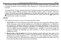
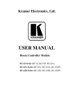
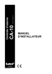
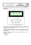
Keypad description.
The keypad displays information on a 2-line
alarm
LCD display (2x16 characters) with backlight
5 Sep, 13:26:41
and six additional LED controls.
System OK
LED controls' functions:
armed
A
B
C
D
trouble
• alarm - signals occurrences of alarms.
• trouble - the LED is blinking when the
1
abc 2
def 3
control panel detects a technical problem
or a telephone messaging trouble,
ghi 4
jkl 5
mno 6
• armed: A B C D - partition status
pqrs 7
signaling:
tuv 8
wxyz 9
- blinking (while the alarm control is off)
0
#
¾
signals exit delay running,
- control stays on when the partition is
Figure 1. View of LCD-S
armed.
The LEDs marked with letters A B C D correspond to numerical denotation of partitions
available in the system:
LED A – partition 1
LED B – partition 2
LED C – partition 3
LED D – partition 4
CONTROL ALARM PANEL CA-10 LCD
4
Programming and Installation Manual
SATEL
The function of LED controls changes after user or service mode is entered, according to the
principles of status communicating by LED keypads (c.f. "CA10 plus with LED keypad user
manual").
The keypad has 12 keys, labeled according to telephone data input standard. Additional four
arrow keys support MENU navigation and selecting functions. After a function has been
chosen, the arrow keys support programming. The keys W and X move the cursor, the key
S backspaces deleting the character that proceeds the cursor and the key T toggles the
data input mode (insert or overwrite).
Modes.
The keypad can function in one of the following three modes:
1. Text mode: the first line displays system date and time. The second line displays system
status messages, which can be standard (e.g. SYSTEM OK, ARMED etc.), or defined by
the installer (e.g. SERVICE 505-34-77 instead of SYSTEM TROUBLE). In this mode it is
possible display all current messages alternately or according to priority. In priority mode
only the highest priority message is displayed (e.g. ALARM). In non-priority mode all
relevant messages are displayed one after another in a closed cycle (e.g. ALARM and
ARMED by turns).
2. Mixed mode, LCD standard: the first line displays system date and time while in the
second line the status of all 16 zones is being monitored. The status of each zone is
displayed as a single character (e.g. * = zone OK, N = zone violated). After a change in
the system status (e.g. after arming the system) the keypad displays the status as in the
first mode and after a while turns to zone monitoring.
CA10 plus
LCD-S keypad
5
3. Mixed mode, LED standard: this mode is similar to the second one. The second line is
used to monitor the status of 12 zones as in the case of LED keypad.
Operating mode 1 or 2 is recommended for the LCD-S keypad. The user can temporarily
change the display mode, switching over between the text mode and the zone state display
by holding down the Tkey.
LCD-S keypad installation
The keypad is designed to operate indoors in normal humidity. It should be mounted straight
on a flat surface.
Attention: The LCD display is fragile. It can be damaged when dropped.
6
Programming and Installation Manual
SATEL
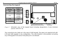
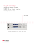
Connecting the keypad.
KPD
DTA
CLK
COM
RS-232
Z2
Z2 – to detector
Additional
system zones
Z1
Z1 – to detector
+KPD
DATA
CLK1
or CLK2
or CLK3
or CLK4
COM
COM CLK DTA KPD
DESCRIPTION OF TERMINALS
KEYPAD
PANEL
anti-tampering contact
beeper
Figure 2. Schematic view of the keypad board including designations of wire terminals
(version LCD-S V1.6).
The connections are made as in the case of LED keypad. The panel can operate both with
LCD and LED keypads in any configuration. The only limitation is that parallel connecting
any LCD keypads to the same CLK panel port is not allowed.
CA10 plus
LCD-S keypad
7
Only zone expanders with version 2 are allowed (label dated February 1998 or later). Since
LCD keypads take larger current then LED keypads (especially when back-lighting is on),
wire resistance must be taken into account in the case of supply and earth cables.
The LED keypad address setting jumpers (DCBA) have been replaced in the version 3.00
with a parameter programmed by means of the service function of the LCD-S keypad. The
keypad address can be changed in two ways:
1. Directly (skipping the service code):
• Disconnect the keypad power supply and the data bus wires (CLK, DATA).
• Short-circuit the CLK and DATA terminals of the keypad.
• Switch on the keypad power supply. The following text will be displayed:
„Keypad hardware address: 1001” (the default value, corresponding to the jumpers
read out in the ABCD sequence).
• Using the [0] and [1] keys, enter the proper address and then press the [#] key. The
„Address set” text will be displayed on the keypad.
• Connect the keypad to the control panel in appropriate way (CLK, DATA).
NOTE:
For correct handling of the LCD-S keypads by the CA-10 plus control panel, the
FS-124 function must be performed on each of the LCD-S keypads connected to
the panel.
8
Programming and Installation Manual
SATEL
2. By means of the keypad service functions:
• Activate the control panel service mode [SERVICE CODE][#].
• Select in turn the items in menu of displayed functions: Æ LCD keypad; ÆSettings;
ÆKeypad address.
• Using the [0] and [1]keys, enter the proper address and then press the [#] key. The
keypad will display the text:
„Set addresses (FS 124) ? 1=Yes”.
• Press the [1] key to automatically perform the FS-124 service function and save the
settings.
The functions of the other keypad jumpers have been replaced by the options available in
the submenu of the LCD-S keypad service functions (ÆLCD keypad; ÆSettings;
ÆOptions). These options have the following descriptions:
à Long illumination (T jumper function) – if not selected, the option will set the 40s
time, and when selected, it will set the 150s time of waiting for no key depressed
(e.g. when reviewing the zones state after holding down the T key, the review will
be ended by the keypad after the time set with this option if no key is pressed).
à Permanent illumination (L jumper function) – if selected, this option will cause a
permanent backlighting of the keypad and a dim permanent backlighting of the
display, irrespective of the keypad settings indicated in the service mode.
As the LCD-S keypad consumes more power than the LED keypads (especially when the
illumination of keypad and display is on), it is important that resistance of the power cables
and grounding conductors be taken into account when planning the cable layout.
CA10 plus
LCD-S keypad
9
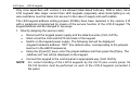
In the case of standard 8x0.5 cable to ensure proper keypad function the following number of
wires versus the panel-keypad distance should be used.
Distance
Connection
Number of wires
up to 50 m
KPD and COM
CLK and DTA signals
2x1
2x1
KPD and COM
CLK and DTA signals
KPD and COM
CLK and DTA signals
2x2
2x1
2x4
2x1
up to 100 m
up to 200 m
Note:
the keypad power supply voltage (measured between "KPD" and "COM" on the
keypad side) must not drop below 11V when the back-lighting is on.
After the control panel power up, the keypad can display message "Change panel's EPROM
or set the correct keypad address". This is usually because the keypad address is different
than the one programmed in the panel. In this case start the panel according to the
instructions in -"CA10 plus Programming Manual", section "Starting the Control Panel".
NOTE: We recommend keypads: CA-10 LED M v1.2 and CA-10 LED S v1.2 or newer to be
used, because older keypads LED M and LED S may work incorrect with keypad LCD v3.08
(and next version).
10
Programming and Installation Manual
SATEL
Service mode
After the service mode code, terminated with [#] or [*], is entered, the panel enters the
service mode. This is signaled in the keypad by the following message:
Service mode
Menu: ÇÈÅÆ
Press any arrow key to enter multi-level service mode menu which provides easy access to
service functions. The functions are grouped by subject. The arrow keys ST scroll the list of
the current level of the menu. The key X expands the next (lower in hierarchy) menu level.
The key W turns back to the previous (higher in hierarchy) level.
CA10 plus
LCD-S keypad
11
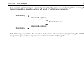
For example if Monitoring is selected (pointed by the arrow on the display) then pressing X
twice followed bye pressing W twice will result in the following sequence:
Monitoring Ö
Stations & options
Ö
Station 1 tel. no.
Õ
Stations & options
Monitoring Õ
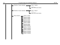
The following pages show the structure of the menu. The functions programming the LCD-S
keypad are grouped in a separate menu described later in this guide.
12
Programming and Installation Manual
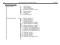
SERVICE MODE MENU
Basic Options
1. Service code
2. Panel identifier
3. Computer identifier
4. Computer telephone number
5. System Options
6. Global times
7. Counters
123. Counters timers
Partitions definition
8. Zones of partition 1
9. Zones of partition 2
10. Zones of partition 3
11. Zones of partition 4
12. Zones displayed on keypad1
13. Zones displayed on keypad2
14. Zones displayed on keypad3
15. Zones displayed on keypad4
16. Partition 1 auto-bypassed zones
17. Partition 2 auto-bypassed zones
18. Partition 3 auto-bypassed zones
19. Partition 4 auto-bypassed zones
20. Partition 1 options
21. Partition 2 options
22. Partition 3 options
23. Partition 4 options
127. Partition 1 exit-bypass zones
SATEL
CA10 plus
LCD-S keypad
13
128. Partition 2 exit-bypass zones
129. Partition 3 exit-bypass zones
130. Partition 4 exit-bypass zones
Zones
24. Zones sensitivity
25. Zone type
26. Reaction type
27. Zone options
28. Entry delays
29. Maximum violation time
30. Minimum no violation time
Outputs
31. Output OUT programming
32. Zones assigned to OUT1
33. Output OUT programming2
34. Zones assignee to OUT2
35. Output OUT programming3
36. Zones assignee to OUT3
37. Output OUT programming4
38. Zones assignee to OUT4
39. Output OUT programming5
40. Zones assignee to OUT5
41. Output OUT programming6
42. Zones assignee to OUT6
14
Programming and Installation Manual
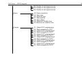
Monitoring
Stations
43. Station 1 telephone number
44. Station 2 telephone number
45. Station 1 transmission format
46. Station 2 transmission format
47. Monitoring options
Identifiers
48. Zone events' ID for station 1
49. Partition 1 events' ID for station 1
50. Partition 2 events' ID for station 1
51. Partition 3 events' ID for station 1
52. Partition 4 events' ID for station 1
53. System events' ID for station 1
54. Zone events' ID for station 2
55. Partition 1 events' ID for station 2
56. Partition 2 events' ID for station 2
57. Partition 3 events' ID for station 2
58. Partition 4 events' ID for station 2
59. System events' ID for station 2
138. VISONIC addr.
139. VISONIC test
Zone report codes
60. Zone alarm
61. Zone tamper
62. Zone trouble
63. Zone violation
64. Zone restore
65. Tamper restore
66. Trouble restore
67. Assignment to station 1
68. Assignment to station 2
SATEL
CA10 plus
LCD-S keypad
15
Partition report codes
System report codes
69. Partition 1 events
70. Partition 2 events
71. Partition 3 events
72. Partition 4 events
73. Partition 1 events assignment to station 1
74. Partition 2 events assignment to station 1
75. Partition 3 events assignment to station 1
76. Partition 4 events assignment to station 1
77. Partition 1 events assignment to station 2
78. Partition 2 events assignment to station 2
79. Partition 3 events assignment to station 2
80. Partition 4 events assignment to station 2
81. System events set 1
82. System events set 2
83. System events assignment to station 1
84. System events assignment to station 2
85. Test transmission time
86. AC loss report delay
126. Guard control report codes
133. Time of test transmission every
134. Zone bypass codes
135. Zone unbypass codes
136. Prefix for extension of identifiers (TELIM)
137. TELIM codes
16
Programming and Installation Manual
Tel. messaging
Tel. numbers
Pager messages
Timers
87. Telephone number 1
88. Telephone number 2
89. Telephone number 3
90. Telephone number 4
91. Telephone number 5
92. Telephone number 6
93. Telephone number 7
94. Telephone number 8
95. Partitions and messages assignment
96. Message 1
97. Message 2
98. Message 3
99. Message 4
Messages (HEX mode)
119.
120.
121.
122.
Message 1 (HEX)
Message 2 (HEX)
Message 3 (HEX)
Message 4 (HEX)
Messaging options
100.
101.
117.
118.
Tel. queue and attempts
Rings to answer
Tel. line loss recognition delay
PAGER station parameters
102. Timer 1
103. Timer 2
104. Timer 3
105. Timer 4
106. Timers’ functions
SATEL
CA10 plus
LCD-S keypad
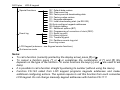
Special functions
Event log
17
107. Default data restore
108. Clear event log
109. Factory service downloading data
110. Factory codes restore
111. Keypads addresses
112. Local downloading start (via RS-232)
124. Auto-configure keypads addresses
125. Outputs testing
131. Additional options (BIT)
132. Programming of correction of clock (DEC)
113. Event log print
114. Alarm log print
115. Trouble log print
116. Partitions events log print
Event log review
LCD Keypad (submenu - see Keypad service functions)
Quit service mode
Notes:
• To call a function (currently pointed by the display arrow) press [#] or X.
• To cancel a function press [*] or W or sometimes the combination of [*] and [#] (this
depends on the type of the function - in some functions the keys [*] and W are used to edit
data).
• It is possible to call a function straight by entering its number (without using the menu).
• Function FS-124 called from LCD keypad programs keypads addresses and makes
additional configuring actions. The system require to call this function from each connected
LCD keypad. Do not change manually keypad addresses with function FS-111!
18
Programming and Installation Manual
SATEL
Bit functions
After a bit function is called the keys W X will change the cursor position and the keys ST
will the value of the bit at the cursor position. It is also possible to enter the desired bit
number with the numeric keys. Bit numbers 10-16 are entered by pressing [*] followed by the
key with the second digit. The combination of [*] and [#] terminates the function.
In this way variables of type "zone list" are programmed (e.g. Programming partition zones).
Bit functions with a list
After a bit function with a list is called in the first line of the display the function name will be
shown, while in the second line the first position in the bit switch list is displayed (e.g. System
options). The character indicates that the option is on. To change the switch state press
any numeric key. The keys ST will scroll the switch list.
Multiparameter functions
In the case of functions which are used to program several parameters. The keys ST
choose the parameter to be modified, the key W deletes the character which proceeds the
cursor and the key X cancel any changes to the currently edited parameter. Parameter
values are entered with numeric keys. To enter HEX digits A-F press [*] followed by one of
the digits 0-5.
CA10 plus
LCD-S keypad
19
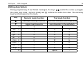
Editing descriptions
During programming of text format messages, the keys W X control the cursor, [*] toggles
the mode (text mode / numeric mode) and [#] confirms the entire text value. The remaining
keys function depend on the mode.
Key
Numeric mode function
S
delete proceeding character
T
toggle insert/overwrite
Text mode function
previous character (in the alphabet)
next character (in the alphabet)
1
1
.
,
abc
2
2
A
a
def
3
3
D
d
ghi
4
4
G
g
jkl
5
5
J
j
mno 6
6
M
m
pqrs
7
7
P
p
tuv
8
8
T
t
wxyz 9
9
W
w
0
0
space
-
20
Programming and Installation Manual
SATEL
The text mode is signaled by * in the upper right corner of the display. Use numeric keys to
enter characters according to the table. Lowercase characters are obtained by pressing the
corresponding numeric key twice. To cancel programming a description, press sequentially
[*] and [#] while in the numeric mode.
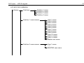
Keypad service functions
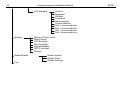
Keypad service functions are available in the panel service mode through the submenu LCD
Keypad at the top level of the Service mode menu. The structure of the submenu follows:
CA10 plus
LCD-S keypad
21
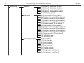
LCD KEYPAD SUBMENU
Names
Partitions
Partition 1 name
Partition 2 name
Partition 3 name
Partition 4 name
Partition 1 users names
Partition 2 users names
User 1 name
User 2 name
User 3 name
User 4 name
User 5 name
User 6 name
User 7 name
User 8 name
User 9 name
User 10 name
User 11 name
User 12 name
Master user name
User 1 name
xxxxx
MASTER user name
22
Programming and Installation Manual
Partition 3 users names
User 1 name
xxxxxx
MASTER user name
Partition 4 users names
User name1
xxxxxx
MASTER user name
Zone names
Zone 1 name
Zone 2 name
Zone 3 name
Zone 4 name
Zone 5 name
Zone 6 name
Zone 7 name
Zone 8 name
Zone 9 name
Zone 10 name
Zone 11 name
Zone 12 name
Zone 13 name
Zone 14 name
Zone 15 name
Zone 16 name
SATEL
CA10 plus
LCD-S keypad
23
Output names
Output 1 name
Output 2 name
Output 3 name
Output 4 name
Output 5 name
Output 6 name
Texts
System ok.
System Armed
Silent Arm
Arming
Arming Silent
Disarming
Zones bypassed
Alarm !
Fire Alarm
Alarm Memory
Fire Memory
Alarm off
Trouble
Entry Time
Exit Time
Time Left:
Wait for data...
Symbols
CA-10+ standard
led off
led on
numbers of zones to display
24
Programming and Installation Manual
LCD standard
Settings
Reset Defaults
Test
Zone ok.
Bypassed
Violated
Tampered
Alarm memory
Tamper Memory
Part. 1 zones selection
Part. 2 zones selection
Part. 3 zones selection
Part. 4 zones selection
Date and Time Format
State Format
LCD Backlight
Keys backlight
Keypad address
GOTO functions
Options
Default names
Default Texts
Default Settings
SATEL
CA10 plus
LCD-S keypad
25
Partition names
The functions are used to program partition descriptions which are displayed when GOTO
function is called. The name of the current partition is displayed when the key T is pressed.
Partition users names
User names are used when the system is armed, disarmed or when the event log is
reviewed.
Zone names
The names are used when event log is being reviewed, violations and alarms occur and
when service functions used to set zone parameters are called.
Output names
The names are used to indicate destination of panel outputs. They are displayed when event
log is being reviewed or output functions are being programmed (in the service mode).
Texts
Standard system messages (like "alarm", "armed" etc.) can be modified with this function
according to user preferences and requirements of a specific installation.
26
Programming and Installation Manual
SATEL
CA10 plus LED standard characters
In zone monitoring mode, according to LED standard, the character 9 corresponds to LED
control on and corresponds to LED off. It is possible to change these characters some
other. The parameter "number of zones to be displayed" is used to limit the number of
monitored zones in the case when some are not used (c.f. service functions 12..15, control
panel user manual). This can be necessary after switching to another partition with GOTO
function.
LCD standard characters
Characters which signal various zone states in zone monitoring mode, LCD standard, can be
modified here. The {choice of zones} option can be used to eliminate non existing zones.
NOTE: The choice of zones is used to select zones which are to be displayed as violated or
alarming zones by corresponding panel functions. This is primarily used in text
mode to limit the displayed names of zones to the set of zones of the current
partition (to which the keypad is currently attached).
CA10 plus
LCD-S keypad
27
Time format
Display back-light
Keypad back-light
The above functions to choose the format of date and time to be displayed in the first line of
the display and the back-light status of the display and the keypad. Symbols to be used: 0 back-light off, 1/2 - weak back-light, 1 - full back-light, auto - back-light is turned on after a
key is pressed and then turned off after time set with use of option “Long illumination” (40 or
150 seconds)
Status format
The function selects the panel's operation mode:
• text mode ("descriptions"): system status is communicated by means of textual
messages,
• zones according to CA10 plus mode: status of maximum of 12 zones is displayed
according to the list programmed with panel service functions FS12-FS15,
• zones according to LCD mode: status of maximum of 16 selected zones is displayed,
indicating violations, alarms, tamper conditions, alarm log etc.
28
Programming and Installation Manual
SATEL
GOTO function
GOTO function performed on LCD-S keypad is easier then on LED one. LCD-S keypad
allows zone switching without returning to the base zone (the key [*]). This menu selects
partitions to which switching with GOTO is allowed.
Activation of the function needs programming service function of LCD keypad. In menu
Settings ¤ Function GOTO we can specify the partitions to which we can go with GOTO
function.
After confirming the partitions selection LCD keypad will perform FS-124 service function,
which will set addresses of LCD keypads proper for the current configuration.
Notes:
•
If more than one LCD keypad is installed in the system, function GOTO settings
should be separately programmed in each keypad.
In the case of installation with an LCD-S keypad, expanders adapted to LCD keypads
should be used (software version 2, manufactured since February 1998). Older
expander versions will also operate with LCD-S keypads, but will not support
multipartition systems.
CA10 plus
LCD-S keypad
29
Options
The functions enables setting some additional parameters, such as:
• display exit delay time left,
• exit delay sound signaling type,
• beep on key pressed,
• change back-lighting on key pressed,
• how long to wait for pressing next key (40s / 150s),
• is illumination of keypad and display to be permanent,
• are functions assigned to arrow keys to be active.
{Status priority} parameter determines the way system status is displayed in the text mode. If
it is off all relevant messages are displayed one after another in a closed cycle. If it is on only
the highest priority message is displayed. The following priority levels are assigned by
default (starting with the highest):
1. entry delay,
2. fire alarm,
3. burglary alarm,
4. armed (or silent armed)
5. fire alarm occurred,
6. burglary alarm occurred,
7. exit delay.
30
Programming and Installation Manual
SATEL
Reset Defaults
The function restores default parameters of keypad.
Test
The function enables keypad functioning correctness to be tested. Starting this function
restores default keypad parameters. To preserve your own parameters it is necessary to
write them into computer before testing, and after testing they should be again programmed
from the computer. Pressing key [*] after end of testing will restart keypad.
Computer supported programming
All keypad parameters can be programmed from the computer by means of the DLOAD10
program (version 1.00.03 and later) working in the WINDOWS environment. The program
serves also the previous versions of LCD keypads. Use the cable for panel programming to
connect the keypad to the computer RS-232 port. No initialization is required - the keypad
will automatically respond to DLOAD10 commands.
CA10 plus
LCD-S keypad
Specifications
Minimum power supply voltage.................................................................................... 11 V
Maximum power supply voltage................................................................................... 16 V
Maximum current .................................................................................................... 170 mA
Current drawn
logic circuits ........................................................................................................ 30 mA
keypad back-lighting........................................................................................... 20 mA
LED controls on (all: ALARM, TROUBLE, ARMED) ........................................... 20 mA
display back-lighting 1/2 (weak).......................................................................... 35 mA
display full back-lighting.................................................................................... 100 mA
Dimensions ................................................................................................. 115x95x25 mm
31
32
Programming and Installation Manual
SATEL
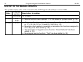
HISTORY OF THE MANUAL UPDATES
The updates below refer to the manual for the LCD Keypad with software version 3.00.
Date
01-2003
07-2003
Program
version
3.01-3.06
3.07
3.08
3.10
Description of updates
No changes.
• Service function menu updated – FS 133 added to “system codes” (p. 15).
• The service functions menu has been enhanced by new functions: FS 125
(p. 17), FS 134-137 (p. 15) and FS 138-139 (p. 14).
• New option that applies to possibility of activation the functions assigned to
arrow keys has been added (p. 29).
• The description of keypad service function: “Reset Defaults” has been
added (p. 30).
• New keypad service function: “Test” has been added (p. 30).