1
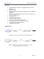
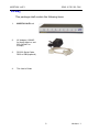
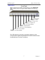
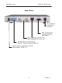
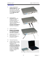
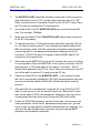
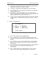
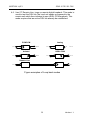
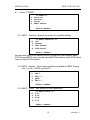
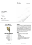
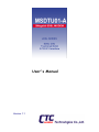
User's Manual
Version 1.1
Contents
Overview ..............................................................................................3
Features...............................................................................................4
Applications..........................................................................................4
Specifications.......................................................................................5
Packing.................................................................................................6
Appearance..........................................................................................7
Front Panel........................................................................................7
Rear Panel.........................................................................................8
Important Safety Instructions ..............................................................9
Installation .......................................................................................... 11
Hardware Setup................................................................................. 12
Point-to-point Operation .................................................................... 14
Console Operation............................................................................. 15
Console Operation / Configuration ................................................... 16
Cables ................................................................................................ 20
Version History
V1.0 released May 7, 2001
V1.1 released September 24, 2001
firmware 1.14, supports connection to datacom unit
1
Version 1.1
2
Version 1.1
MSDTU01-A/E1
SDSL G.703 E1 CSU
Overview
The MSDTU01-A/E1 SDSL with G.703 Fractional E1 interface is a
data access Channel Service Unit modem with the latest multi-rate
HDSL (High-speed Digital Subscriber Line) technology offering both
long range and high speed data transmission with Nx64 rates from
128Kbps up to 2048Kbps. The transmitting data rate may be adapted
for the best "rate vs. range" performance for efficient and stable data
transmission.
The MSDTU01-A/E1 uses the 2B1Q line code with echo cancellation
to transmit its high data rate over a single twisted pair of telephone
wires without being affected by bridge taps or mixed cable links. It also
provides high immunity to background noise and enables transmission
over multiple pair cables.
3
Version 1.1
MSDTU01-A/E1
SDSL G.703 E1 CSU
Features
4
4
4
4
4
4
4
4
4
4
4
High speed SDSL transport over single twisted Copper pair
telephone lines
2B1Q line code
Symmetrical Multi-rate Nx64 data transmission from 128Kbps to
2048Kbps
G.703 E1 operates from recovery (E1 at CO), or loop recovery
(E1 at RT) timing modes
Simple operation
Low power consumption
Transparent data over SDSL
Point-to-point data transmission service
Configure and Loop Test via RS-232 Craft port
Local and remote loopback features
Integral BERT generator
Applications
Application : Point-to-Point Connection for Network Extension
Application : Point-to-Point Connection with V.35 Data Com Unit
(Must be at least version 1.4 firmware.)
4
Version 1.1
MSDTU01-A/E1
SDSL G.703 E1 CSU
Specifications
Item
Channel Port
MSDTU01-A/E1
Interface
ITU-T G.703 E1
Connector
Impedance
BNC(x2) unbalanced, RJ-45 Balanced
75 or 120 Ohms, selectable
75 Ohm: Pulse 2.37V nominal
120 Ohm: Pulse 3.00V nominal
0 to –43dB
2.048Mbps
HDB3
Unframed, CAS, CCS, CRC4 On/Off
Recovery at CO, DSL Loop Recovery
Meets ITU-T G.823
ITU-T G.703, G.704, G.706, G.732
Tx Level
Relative Rx Level
Bit Rate
Line Code
Framing
Timing Source
Jitter Tolerance
Complies with
WAN Port -SDSL Line I/F
Indicators
LED
Transmission Rate : 144 Kbps – 2320 Kbps
Data Rate :
Line Code
Line Impedance
Test Standard
Connection Loops
Connector
Power
(WAN)
LOS
LFA
ALARM
LOOP
(E1)
SigLoss
SyncLoss
ALARM
LOOP
144 Kbps – 2320 Kbps
2B1Q
135 Ω
ANSI T1E1.413/94-006; ETSI ETR 152
One Pair (2-wire)
RJ-11
Green LED, indicate power and operation
Red LED, DSL Loss of Signal
Red LED, DSL Loss of Frame Alignment
Red LED, DSL Test & Error status
Red LED, DSL in Loopback mode
Red LED, E1 Signal Loss
Red LED, E1 Sync Loss
Red LED, E1 Alarm
Red LED, E1 in Loopback mode
OAM&P
Local
ASCII Terminal via EIA RS-232 Port
Environment
Temperature
Humidity
0°C ~ 50°C
5% ~ 95%
Dimensions
(WxDxH)
CO/RT
213(w)mm X 152(d)mm X 25(h)mm
Electrical
Power Input
12VDC via AC Adapter
Power Consumption Less than 8 Watts
5
Version 1.1
MSDTU01-A/E1
SDSL G.703 E1 CSU
Packing
This package shall contain the following items:
1.
MSDTU01-A/E1 unit
2.
AC Adapter (120VAC
for North America, and
220-240VAC for
Europe)
3.
RS-232 Serial Cable,
DB-9 to DB-9(optional)
4.
This User's Guide
6
Version 1.1
MSDTU01-A/E1
SDSL G.703 E1 CSU
Appearance
Front Panel
After connecting all cables and powering on the MSDTU01A/E1, LED’s on the front panel shall indicate the following
status.
LOOP
– Test/Loopback
ALARM – E1 Alarm
SyncLoss – E1 Sync Loss
SigLoss – E1 Signal Loss
LOOP – DSL Test/Loopback
ALARM – DSL Alarm/Error
LFA – DSL Loss of Frame Alignment
LOS – DSL Loss of Signal
POWER – Unit Power Applied
The LED indicators provide an excellent indication of the
communication status and possible link trouble locations when
troubleshooting "link-down" problems.
7
Version 1.1
MSDTU01-A/E1
SDSL G.703 E1 CSU
Rear Panel
RJ11, SDSL for
connection to
local loop
DB9, console port for
connection to ASCII
data termina l
RJ-45, Balanced G.703 E1 Port,
BNC, Unbalanced G.703 E1 Port
10P DIP switch, for setting speed,
CO/CPE, Timing, E1 Framing, Nx64, etc.
Power Jack, for connecting to a AC-DC
power adapter, 12VDC, 1A
8
Version 1.1
MSDTU01-A/E1
SDSL G.703 E1 CSU
Important Safety Instructions
The following safety instructions apply to the MSDTU01-A/E1:
1.
Be sure to read and follow all warning notices and instructions.
2.
The maximum recommended ambient temperature for MSDTU01-A/E1
is 40? (104? ) Care must be taken to allow sufficient air circulation or
space between units when the MSDTU01-A/E1 is installed inside a
closed rack assembly. The operating ambient temperature of the rack
environment might be greater than room temperature.
3.
Installation in a rack without sufficient air flow can be unsafe.
4.
Racks should safely support the combined weight of all equipment.
5.
The connections and equipment that supply power to the MSDTU01A/E1 should be capable of operating safely with the maximum power
requirements of the MSDTU01-A/E1. In the event of a power overload,
the supply circuits and supply wiring should not become hazardous.
The input rating of the MSDTU01-A/E1 is printed on the nameplate.
6.
The AC adapter must plug in to the right supply voltage, i.e. 120VAC
adapter for North America and 230VAC adapter for Europe. Be sure the
supplied AC voltage is correct and stable. If the input AC voltage is
more than 10% lower than the standard may cause malfunction of the
MSDTU01-A/E1 unit.
7.
Installation in restricted access areas must comply with Articles 110-16,
110-17, and 110-18 of the national Electrical Code, ANSI/NFPA 70.
8.
Do not allow anything to rest on the power cord of the AC adapter, and
do not locate the product where anyone will walk on the power cord.
9.
Do not service the product by yourself. Opening or removing covers
can expose you to dangerous high voltage points or other risks. Refer
all servicing to qualified service personnel.
10. Generally, when installed in the final configuration, the product must
comply with the applicable safety standards and regulatory
requirements of the country in which it is installed. If necessary,
consult the appropriate regulatory agencies and inspection authorities
to ensure compliance.
9
Version 1.1
MSDTU01-A/E1
SDSL G.703 E1 CSU
11. A rare condition can create a voltage potential between the earth
grounds of two or more buildings. If products installed in separate
building are interconnected, the voltage potential can cause a
hazardous condition. Consult a qualified electrical consultant to
determine whether or not this phenomenon exists and, if necessary,
implement corrective action before interconnecting the products. If the
equipment is to be used with telecommunications circuit, take the
following precautions:
4
Never install telephone wiring during a lightning storm.
4
Never install telephone jacks in wet location unless the jack is specially
designed for wet location.
4
Never touch uninsulated telephone wires or terminals unless the
telephone line has been disconnected at the network interface.
4
Use caution when installing or modifying telephone lines (other than a
cordless telephone) during an electrical storm. There is a remote risk of
electric shock from lightning.
4
Do not use a telephone or other equipment connected to telephone
lines to report a gas leak in the vicinity of the leak.
10
Version 1.1
MSDTU01-A/E1
SDSL G.703 E1 CSU
Installation
1. Connect the local loop
(twisted copper pair
telephone wire) to the WAN
port at the RJ-11 jack. Be
sure that this local loop has
been properly connected to
another MSDTU01-A/E1
remote unit.
2.
Connect the E1
transmission line to the
modem at the BNC
connectors marked "TX"
and "RX". Alternately,
connect the twisted pair E1
cable to the RJ-45
connector. Please refer to
the section on "Cables" for
detailed pin assignment.
3.
•
Power connection --
•
•
4.
•
Warning : Do not apply
the AC power before all
the connections above
have been connected.
Connect the DC jack to the
DC-IN of the unit
Plug in the AC Adapter to
the wall AC socket
Terminal Connection -A data terminal or PC with
emulation software can be
connected to the
TERMINAL port (RS-232)
of the unit for configuration
& monitoring purpose. Use
an RS-232 serial cable to
connect to a ASCII data
terminal. The TERMINAL
should be VT-100
compatible.
11
Version 1.1
MSDTU01-A/E1
SDSL G.703 E1 CSU
Hardware Setup
DSL rate and terminal type can be set up by adjusting the 10-pole DIP
switch on the rear panel. Sw. 1 is for SDSL termination type, Sw.2 thru Sw. 6
are for adjusting the E1 and DSL rate, Sw. 7 will disable TS0, Sw. 8 and Sw.
9 set E1 frame mode, and Sw. 10 sets the E1 line termination.
ON
1
1.
Rate Setting Table
E1 Rate
(TS0+data)
128K
ON
OFF
OFF
OFF
OFF
TS used
for data
1
192K
OFF
ON
OFF
OFF
OFF
2
208K
144K
256K
ON
ON
OFF
OFF
OFF
3
272K
208K
320K
OFF
OFF
ON
OFF
OFF
4
336K
272K
384K
ON
OFF
ON
OFF
OFF
5
400K
336K
448K
OFF
ON
ON
OFF
OFF
6
464K
400K
512K
ON
ON
ON
OFF
OFF
7
528K
464K
576K
OFF
OFF
OFF
ON
OFF
8
592K
528K
640K
ON
OFF
OFF
ON
OFF
9
656K
592K
704K
OFF
ON
OFF
ON
OFF
10
720K
656K
768K
ON
ON
OFF
ON
OFF
11
784K
720K
832K
OFF
OFF
ON
ON
OFF
12
848K
784K
896K
ON
OFF
ON
ON
OFF
13
912K
848K
960K
OFF
ON
ON
ON
OFF
14
976K
912K
1024K
ON
ON
ON
ON
OFF
15
1040K
976K
1088K
OFF
OFF
OFF
OFF
ON
16
1104K
1040K
1152K
ON
OFF
OFF
OFF
ON
17
1168K
1104K
1216K
OFF
ON
OFF
OFF
ON
18
1232K
1168K
1280K
ON
ON
OFF
OFF
ON
19
1296K
1232K
1344K
OFF
OFF
ON
OFF
ON
20
1360K
1296K
1408K
ON
OFF
ON
OFF
ON
21
1424K
1360K
1472K
OFF
ON
ON
OFF
ON
22
1488K
1424K
No.2
No.3
No.4
No.5
No.6
DSL
Rate
144K
TS0 Dis.
DSL Rate
114K
1536K
ON
ON
ON
OFF
ON
23
1552K
1488K
1600K
OFF
OFF
OFF
ON
ON
24
1616K
1552K
1664K
ON
OFF
OFF
ON
ON
25
1680K
1616K
1728K
OFF
ON
OFF
ON
ON
26
1744K
1680K
1792K
ON
ON
OFF
ON
ON
27
1808K
1744K
1856K
OFF
OFF
ON
ON
ON
28
1872K
1808K
1920K
ON
OFF
ON
ON
ON
29
1936K
1872K
1984K
OFF
ON
ON
ON
ON
30
2000K
1936K
2048K
ON
ON
ON
ON
ON
31
2064K
2000K
Unframed
OFF
OFF
OFF
OFF
OFF
32
2064K
2064K
12
Version 1.1
MSDTU01-A/E1
SDSL G.703 E1 CSU
The E1 data rate is equal to the number of timeslots used for data
times 64 Kbps, plus 64 Kbps for timeslot zero (framing timeslot).
The DSL data rate is equal to the E1 data rate plus 16 Kbps overhead.
The TS0 Dis. (Timeslot zero disabled) DSL rate is equal to the number
of timeslots used for data plus 16 Kbps overhead. Use this rate setting to
match a remote datacom unit's HDSL rate ( CCS framing ONLY).
2.
3.
CO/RT configuration
Terminal type
DIP SW No. 1
CO
ON
RT
OFF
Framing, CRC4 and termination configuration
Sw. 7*
Sw. 8
Sw. 9
Sw. 10
TS0
Frame Mode
CRC4
E1 Term.
ON
Disable
CAS**
CRC4 On
75 Ohms
OFF
Enable
CCS***
no CRC4
120 Ohms
* Normal operation with two MSDTU01A/E1 units enable timeslot zero
(TS0). (Please refer to the first application on page 4). If the MSDTU01A/E1
unit is connected over DSL to an MSDTU01A (refer to the second application
on page 4) datacom unit (V.35, X.21, RS-530 or RS-449), then follow these
rules.
1. Unframed E1: Enable TS0 and set E1 rate to "Unframed", set
remote datacom unit's HDSL rate to 2064Kbps (data rate + 16Kbps).
2. CCS framing: Disable TS0 and match the "TS0 Dis" rate to the
remote datacom unit's "HDSL rate" (data rate + 16Kbps). When timeslot zero
is disabled, the unit allows E1 data to transmit transparently to the datacom
side. The E1 side will not send TS0 to the far Datacom. Likewise, the E1 unit
will regenerate TS0 from the Datacom side to send to the connected E1
equipment.
3. CAS framing: Not support when connected to remote datacom unit.
**CAS mode may also be referred to as PCM30. In this mode, both
timeslots 0 and 16 are used for frame alignment and signaling. Other
timeslots are available to carry data.
***CCS mode may also be referred to as PCM31. In this mode,
timeslot 0 is used for frame alignment and all other timeslots are available to
carry data.
13
Version 1.1
MSDTU01-A/E1
SDSL G.703 E1 CSU
Point-to-point Operation
1.
The MSDTU01-A/E1 should be located on each side of the connection.
One side must be set to "CO" and the other side must be set to "RT".
Refer to the section on "Hardware Setup" for the CO & RT setup. Place
the CO side unit towards the E1 timing source.
2.
Insure that both CO & RT MSDTU01-A/E1s are set to the same DSL
rate. For example, 784Kbps.
3.
Make sure that both CO & RT MSDTU01-A/E1s have been connected
to the E1 line properly.
4.
For normal operation, 75 Ohm termination should be selected (DIP sw
no. 10) when connecting the E1 over unbalanced coaxial cable at the
BNC connectors, while 120 Ohm termination should be selected when
connecting the E1 over balanced twisted pair cabling at the RJ-45
connector. DO NOT connect E1 signals to both the BNC and RJ-45
connectors at the same time.
5.
When placing the MSDTU01-A into an E1 network, the source of timing
is very important. Place the MSDTU01-A unit, which is closest to the E1
timing source, in CO mode and set E1 timing to "recovery". The E1
timing will be passed to the RT unit. The E1 device connected to the RT
unit will be able to recover E1 timing from the RT unit.
6.
Check the WAN LED on the MSDTU01-A/E1 -- it will remain lit when
the Link is successfully established. The DSL training process may take
around one minute and the WAN LED will flash during the training
process.
7.
After the DSL link is established, check the E1 setup. Both CO & RT
side E1 must be set to use the same Frame Type. Both side E1 must
also set the same E1/DSL rate parameter. Otherwise, they may fail to
communicate with each other even though the DSL link is ready.
8.
Follow the DSU/CSU manual to set the Frame type, clock source and
other parameters. When the E1 parameters are properly set, you are
ready to use the high-speed connection between the two networks. You
may test the data transportation speed by using the internal BERT
generator and loopback commands.
14
Version 1.1
MSDTU01-A/E1
SDSL G.703 E1 CSU
Console Operation
Starting Hyper-Terminal (on Windows 95 or Windows NT)
To Start the Hyper-terminal, following the steps below:
1. Start "Hyper-terminal" program -−
On Windows 95 or Windows NT : start Tool Bar à Program à
Accessory à Hyper Terminal Group à Double Click
Hypertrm.exe à Enter Connection Name à Select Icon à Click
OK
2. Select COM port to communicate with the MSDTU01-A/E1-−
Choose direct to COM1 or COM2 à click OK
3. Set up Port Properties -n Port Setting :
−
Bit per second : 9600
−
Data bits : 8
−
Stop bits : 1
−
Parity bit: None
−
Flow Control : None
n Settings :
−
Function, arrow, and ctrl keys act as : Windows keys
−
Emulation : Auto-detect
−
Back-scroll buffer lines : 500
n ASCII Setup:
−
Echo typed characters locally
−
Line delay : 0 milliseconds
−
Character line feeds t incoming line ends : enable
15
Version 1.1
MSDTU01-A/E1
SDSL G.703 E1 CSU
Console Operation / Configuration
1.1 Turn on the power of MSDTU01-A/E1 and press any key, the initial
terminal screen will be displayed. From any other menu, pressing ESC
and Enter will return to the top menu screen. Pressing "zero" will exit
any menu to the next higher level. :
1.
2.
3.
4.
[MSDTU-01A]
xDSL status
BERT
Loopback Test
Information
Select Number :
2.1 Information display— Press "4" to display information
<< Information >>
Firmware Version : 1.14
Hardware Version : 1.1
FPGA Version : 1
CTC UNION TECHNOLOGIES CO., LTD.
http://www.ctcu.com/
The firmware version, hardware version and FPGA version will be
displayed. This information should be readily available to give to
technical support in the event there are difficulties in configuring or
applying the units.
3.1 xDSL status display -<< Status >>
Terminal Type : HTU-C
Symbol Rate : 336Kbps
In Sig Level : 015dB
Far-End Signal Atten. : 002dB
Noise Margin :-15.5dB
Tx Gain : -0.48dB
Descriptions of xDSL status items -3.1. Terminal Type : Indicates whether the Terminal Type of this unit is
set for Central Office (HTU-C) or Remote Terminal (HTU-R). In pointto-point operation, one unit must be set to CO while the other must
be set to RT.
16
Version 1.1
MSDTU01-A/E1
SDSL G.703 E1 CSU
3.2. Symbol Rate : Indicates the DSL rate in kilobits per second. This is
normally the data rate plus 16Kbps overhead.
3.3. In Sig Level : Indicates the input signal level of the DSL signal.
3.4. Far-End Signal Atten. : An approximate calculation of overall cable
signal attenuation in dB.
3.5. Noise Margin : Shows Noise Margin value. The noise margin is
defined as the maximum tolerable increase in external noise that still
allows for a BER (bit error rate) of less than 10-7.
3.6. Tx Gain : Shows current transmission gain level in decibels. Nominal
transmit power is 13.5dBm, while Tx gain may vary from –1.6dB to
+1.4dB.
4.1 Select "3" Loopback Test
<< Loopback >>
*1. OFF
2. PCM-PCM
3. Analog
4. Isolated
5. HDSL-PCM
6. Remote Line
Select Number : _
4.1. Item "1" OFF, will turn off any loopback mode.
4.2. Item "2" PCM-PCM, turns on PCM-PCM loopback mode. In this
mode, the E1 signal coming in the Rx terminal is looped to the E1 Tx
terminal.
4.3. Item "3" Analog, turns on analog loopback mode. In this mode the
local DSL Tx is looped back to local Rx. The DSL cable MUST be
disconnected.
4.4. Item "4" Isolated, turns on isolated analog loopback. This loopback is
the same as item "3", except the DSL cable need not be
disconnected.
4.5. Item "5" HDSL-PCM, turns on digital loopback. In this mode the
remote received DSL signal is looped back to the remote unit.
17
Version 1.1
MSDTU01-A/E1
SDSL G.703 E1 CSU
4.6. Item "6" Remote Line, turns on remote digital loopback. This mode is
used to test the DSL link.The local unit sends a command to the
remote unit which then initiates its own HDSL-PCM loopback. This
mode requires that an active DSL link already be established.
PCM-PCM
E1
Analog
DSL
Isolated
E1
X
E1
DSL
HDSL-PCM
DSL
E1
DSL
Remote Line
E1
E1
DSL
Figure examples of Loop back modes
18
Version 1.1
MSDTU01-A/E1
SDSL G.703 E1 CSU
5.1 Select "2" BERT
1.
2.
3.
4.
<< BERT >>
Function
Pattern
Scale
BERT Status
Select Number :
5.1. BERT – Function : Selects the mode of Loop Back testing.
*1.
2.
3.
4.
<< BERT Function >>
OFF
Normal
PCM Framed
PCM Serial
Select Number :
Normal mode selects the selected HDSL payload on a per-timeslot-basis.
PCM Framed BERT tests only the selected PCM timeslots, while PCM Serial
tests the entire PCM channel.
5.2. BERT – Pattern : There are four patterns available for BER Testing;
2e4-1, 2e15-1, QRSS, and 2e23-1
*1.
2.
3.
4.
<< BERT Pattern >>
2e4-1
2e15-1
QRSS
2e23-1
Select Number :
5.3. BERT – Scale : Test duration in bits transmitted.
*1.
2.
3.
4.
<< BERT Scale >>
2^21
2^25
2^28
2^31
Select Number :
19
Version 1.1
MSDTU01-A/E1
SDSL G.703 E1 CSU
5.4. BERT – Status :
<< BERT Status >>
Pattern SYNC : SYNC
Measurement : Complete
Bit Errors : 000
Press '1' to review.
This display is used to review the results of testing. If there is no
pattern sync the display will read "No SYNC". During the testing
process the display will read "In Progress". The accummulated or final
number of errors will be displayed. The register for counting errors is
only 8 bits (256) and will increment back to zero when full.
Cables / Connectors
1.
4
RS-232 Cable for connection to VT-100 type ASCII terminal
TERMINAL (CRAFT) Port DB-9 DCE connector pin assignment, signal
direction, and alarm relay contacts:
MSDTU01-A
4
−
−
−
−
−
−
Pin 2 ------ RXD
è
DTE
Pin 3 ------ TXD
ç
Pin 5 ------ SGND
Pin 6 ------ Alarm relay common
Pin 4 ------ Alarm relay NC (open on alarm)
Pin 9 ------ Alarm relay NO (closed on alarm)
Parameter :
−
−
−
−
Data Speed : 9600 bps
Parity : None
Stop Bit : 1 bit
Character Length : 8 Bits
Modem cable
Terminal cable
1
2
3
5
4
1
2
3
5
4
6
7
6
7
6
7
6
7
8
8
8
8
1
2
3
5
4
male
male
male
20
1
2
3
5
4
female
Version 1.1
MSDTU01-A/E1
SDSL G.703 E1 CSU
E1 BNC Connectors
BNC
TX
RX
Pin
Center
Sleeve
Center
Sleeve
Designation
TTIP
TRING
RTIP
RRING
Direction
From MSDTU01-A
↔
To MSDTU01-A
↔
Function
Transmit data
Signal return
Receive data
Signal return
Direction
↔
↔
From MSDTU01-A
From MSDTU01-A
To MSDTU01-A
To MSDTU01-A
Function
Frame Ground
Frame Ground
Transmit data +
Transmit data Receive data +
Receive data -
Direction
↔
↔
Function
Transmit data
Signal return
E1 RJ-45 Connector
RJ-45
GND
TX
RX
Pin
8
7
4
5
1
2
Designation
GND
GND
TTIP
TRING
RTIP
RRING
WAN DSL Connector
Conn.
TX/RX
Pin
3
4
Designation
TIP
RING
DC - IN Connector
TIP ---- DC12V+
RING – Return (-)
_
+
21
Version 1.1
MSDTU01-A/E1
SDSL G.703 E1 CSU
22
Version 1.1
CTC Union Technologies Co., Ltd.
Far Eastern Edison Science and Technologies Center
(Nei-Hu HI-TEC Park)
6F-3, Lane 360, Nei-Hu Road, Section 1
Nei-Hu, Taipei, Taiwan
Phone:(886) 2.2659.1021 (Rep) Fax:(886) 2.2799.1355
E-mail: [email protected] http://www.ctcu.com